
Electrical Protection Systems & Relays
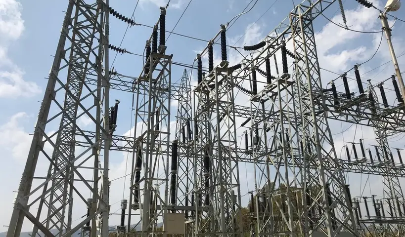
Power systems carry enormous amounts of energy. When something goes wrong, may be a fault, a short circuit, or an insulation failure, that energy needs to be removed from the system fast. That job belongs to protection relays.
Protection relays monitor the electrical quantities in a system. They detect abnormal conditions such as overcurrent, earth faults, and differential faults. They then issue trip commands to circuit breakers within milliseconds.
This page organizes every protection-related article on Wiringuru into one structured reference. Use it to learn a concept, follow a testing procedure, or look up a relay setting.
What Is Electrical Protection and Why It Matters
A power system without protection is a disaster waiting to happen. Faults do not give warnings. Excessive current flowing through equipment windings generates heat according to I²R. That heat can rapidly damage insulation materials, leading to winding failure, oil decomposition, and in severe cases, explosion.
Protection systems stop this from happening. They detect the fault, isolate the faulty section, and allow the rest of the network to continue operating normally.
A well-designed protection scheme has three basic requirements:
- Speed — The relay must operate fast enough to limit damage.
- Selectivity — Only the faulty section should be isolated.
- Reliability — The relay must operate when needed and stay stable when it should not operate.
1. Overcurrent & Earth Fault Protection
Overcurrent protection is the most widely used protection scheme in power systems. Overcurrent protection is the foundation of power system protection engineering. Every electrical network needs a well-coordinated relay protection scheme.
Overcurrent relays monitor line current. When the current exceeds a set threshold, the relay trips the circuit breaker. The relay can operate instantly (ANSI 50) or with a time delay based on an inverse-time characteristic (ANSI 51).
Earth fault protection works alongside overcurrent protection. It monitors for ground fault current, which flows when a live conductor makes contact with earth. Phase faults are characterized by large fault currents that develop when the insulation between phases breaks down, while earth faults occur when phase conductors make contact with grounded equipment or the earth.
However, overcurrent protection has limits. REF protection is particularly useful for detecting earth faults near the neutral point of star-connected transformer windings. In this region, the fault current magnitude is low due to reduced voltage. Overcurrent protection may not be sensitive enough to detect such faults.
📄 Read the Full Article:
👉 Overcurrent and Earth Fault Protection of Transformers
2. Differential Protection
Differential protection compares the current entering a protected zone with the current leaving it. Under normal conditions and external fault conditions, the current entering equals the current leaving. Any difference between these two currents indicates trouble.
Differential protection relays are the primary protective devices used for power transformers, generators, busbars, and large motors in electrical power systems. Differential protection is selective because it only responds to faults within its defined protection zone (between the two current transformers). Faults occurring outside this zone, even on the secondary side just beyond the CT, do not produce sufficient differential current to trip the relay.
This makes differential protection one of the most accurate and zone-specific schemes available.
2.1 Transformer Differential Protection
Transformers, especially those rated 10 MVA and above, require fast, sensitive primary protection. When a differential current exists, the relay operates and sends a trip signal to circuit breakers on both sides of the transformer, isolating it in less than one cycle, typically 40–100 milliseconds.
2.2 Busbar Differential Protection
Busbars are the central connection points in any substation. A fault on the busbar affects every feeder connected to it. The moment a fault develops within the busbar zone such as a phase-to-phase short circuit or a phase-to-ground fault, the current balance is disrupted. Fault current flows from healthy sources toward the fault point. If this differential current exceeds the relay pickup threshold setting, the busbar differential protection relay operates instantaneously and issues trip commands to all circuit breakers connected to the busbar zone.
📄 Read the Full Articles:
👉 Transformer Differential Protection: Relay Setting & Configuration
👉 Testing of Differential Protection Relay: Step-by-Step Procedure
👉 Busbar Differential Protection: Working, Settings & Testing
3. Restricted Earth Fault (REF) Protection
Restricted Earth Fault (REF) protection is a specialized differential protection scheme designed to detect and isolate earth faults occurring near the neutral point of power transformers.
Phase differential protection (87T) becomes less sensitive in the neutral zone because the fault current divides between multiple paths.
When a fault occurs very close to the neutral point within the first 5–15% of the winding, the fault current may be small compared to the phase currents, and the differential element may not detect it reliably.
REF protection eliminates this vulnerability by directly measuring the zero-sequence current (neutral current), which exists only when an earth fault occurs. The REF relay receives current inputs from phase CTs and the neutral CT of the protected equipment.
Under normal conditions and external fault conditions, the vector sum of these currents is zero. When an earth fault occurs within the protected zone, the fault current returns through the neutral and creates an imbalance. The relay detects this imbalance and initiates tripping.
📄 Read the Full Articles:
👉 REF Protection of Transformers: Principle, Settings & Operation
👉 Testing of REF Protection Relay: Step-by-Step Test Procedure
4. Distance Protection
Distance protection is used primarily on high-voltage transmission lines. Instead of measuring current alone, the distance relay measures the impedance between the relay location and the fault point.
Distance protection relays are the primary protective devices used in high-voltage transmission lines across power systems worldwide. These relays measure the impedance between the relay location and fault point to determine whether a fault exists within their protected zone.
When a fault occurs on the protected line, the impedance measured by the relay drops. The relay compares this measured impedance with pre-set impedance values corresponding to different zones of protection.
Modern numerical distance relays like the Siemens 7SA522 series use quadrilateral characteristics or mho characteristics for fault detection. These relays can detect phase-to-phase faults and phase-to-ground faults with high accuracy and selectivity.
4.1 STUB Protection in One-and-a-Half Breaker Scheme
STUB protection covers a specific section of a substation that can become energized and unprotected during certain switching operations. When a line is isolated, the CVT secondary voltage becomes zero. Without the voltage input, the distance protection relay cannot calculate impedance or determine fault location. The relay becomes blind to faults in the STUB section because it lacks the voltage reference signal.
📄 Read the Full Articles:
👉 Distance Protection Relay Testing: Step-by-Step Procedure
👉 STUB Protection in One-and-a-Half Breaker Scheme: Relay Settings
5. Directional Overcurrent & Earth Fault Protection
Standard overcurrent relays trip when current exceeds a threshold regardless of which direction that current is flowing. In a simple radial network, that is fine. In ring main systems or parallel feeders, direction matters.
Directional overcurrent and earth fault relays not only detect fault current magnitude but also identify the direction of fault power flow. This directional feature prevents false tripping and allows selective coordination between multiple protection zones.
In a ring main system, two feeders connect a load from both sides of the bus. If a fault occurs on Feeder A, current will flow from both Feeder A and Feeder B toward the fault point. Without directional sensing, relays on both feeders would trip. This would cause unnecessary power interruption on Feeder B even though it has no fault.
📄 Read the Full Article:
👉 Directional Overcurrent & Earth Fault Relay Testing: Step-by-Step
6. Master Trip (86) Relay
The Master Trip relay is not a fault-detecting device. It is the relay that receives signals from fault-detecting relays and sends the final trip command to the circuit breaker.
A Master Trip Relay (ANSI Function 86) is an instantaneous auxiliary relay that receives trip signals from various protective relays and converts them into a circuit breaker trip command. It acts as a “messenger” between detection devices like differential relays and overcurrent relays and the circuit breaker that needs to be opened during a fault.
The Master Trip Relay operates on a simple electromagnetic principle where a small DC coil current energizes an electromagnet that mechanically closes contacts. These contacts then complete the circuit to the circuit breaker’s trip coil, causing the breaker to open and isolate the faulted section from the healthy network.
📄 Read the Full Article:
👉 Master Trip (86) Relay: Working Principle, Wiring Diagram, Testing
7. Anti-Pumping Relay
Every circuit breaker closing circuit needs a control mechanism to prevent repeated unwanted closure. That is the role of the anti-pumping relay. An anti-pumping relay is a specialized electrical protection device integrated into the closing circuit of circuit breaker control systems to prevent hunting oscillations.
Without this relay, if a close command is held on while a fault exists, the breaker would close, trip, and immediately attempt to close again — repeatedly. This cycle can damage the breaker mechanism and put the system at greater risk.
📄 Read the Full Article:
👉 Anti-Pumping Relay in Circuit Breakers
8. Local Breaker Backup (LBB) Protection
No protection scheme is complete without backup. LBB protection provides fast backup action when the primary circuit breaker fails to trip.
Primary protection operates in 50–100 milliseconds. Primary protection devices are specifically designed to detect and isolate faults within a defined zone. LBB protection is installed at the same location as primary protection but operates independently. It provides rapid backup action without requiring communication with remote terminals.
📄 Read the Full Article:
👉 LBB Protection: Working Principle, Settings, Testing & Examples
9. Secondary Injection Testing for Protection Relays
Before any relay goes into service, it must be tested. Secondary injection testing is the standard method for this. To confirm that these relays operate correctly before they are put into service, engineers perform secondary injection testing.
This test method allows technicians to simulate fault conditions directly at the relay terminals without energizing the primary power system. It is used during factory acceptance tests, site commissioning, periodic maintenance, and after any relay replacement or firmware upgrade. The test verifies pickup values, timing characteristics, and trip logic of the relay independently.
📄 Read the Full Article:
👉 Secondary Injection Testing for Protection Relays: Step-by-Step
10. Static & Solid-State Relays
Before numerical (digital) relays became standard, static solid-state relays were the technology of choice for fast, accurate protection.
Static relays use thyristors, transistors, or optocouplers to drive output relays or directly send trip signals. The entire sequence — from sensing the fault to generating the trip signal — can happen in less than one cycle (less than 20 milliseconds on a 50 Hz system).
Static relays are installed in substations to protect transmission lines, distribution feeders, power transformers, generators, and busbars. They provide fast fault clearance to minimize damage and improve power system stability.
📄 Read the Full Article:
👉 Static Solid-State Relays: Working Principle, Types & Applications
11. GE Multilin 845 Relay — Settings & Configuration
The GE Multilin 845 is a widely used numerical relay designed for the protection of two-winding and three-winding power transformers. It is manufactured by GE Grid Solutions and is deployed across utility substations, industrial plants, and generation facilities around the world.
The relay offers multiple protection functions under a single platform, including transformer differential protection (ANSI 87T), overcurrent protection (ANSI 50/51), restricted earth fault protection (ANSI 87N), overexcitation protection (ANSI 24), and thermal overload protection (ANSI 49).
The relay communicates through standard protocols such as Modbus, DNP3, and IEC 61850. It also features built-in disturbance recording, event logging, and self-monitoring capabilities.
📄 Read the Full Article:
👉 GE 845 Transformer Protection Relay Settings Calculation
Quick Reference: ANSI Device Numbers for Protection Relays
| ANSI Code | Function |
|---|---|
| 21 | Distance Relay |
| 27 | Undervoltage Relay |
| 50 | Instantaneous Overcurrent Relay |
| 51 | Time Overcurrent Relay |
| 59 | Overvoltage Relay |
| 64T | Transformer Restricted Earth Fault Relay |
| 67 | Directional Overcurrent Relay |
| 86 | Master Trip (Lockout) Relay |
| 87T | Transformer Differential Relay |
| 87B | Busbar Differential Relay |
| 87N | Restricted Earth Fault (Numerical) |
Frequently Asked Questions (FAQs)
Primary protection detects and clears a fault within its defined zone as fast as possible usually in 40 to 100 milliseconds. Backup protection operates only if the primary protection fails or the circuit breaker does not open.
A protection relay monitors electrical quantities like current, voltage, or impedance. It detects abnormal conditions such as overcurrent, earth faults, and differential faults. It then issues trip commands to circuit breakers within milliseconds.
Overcurrent protection trips when the current exceeds a set value. It does not know where the fault is — only that the current is too high. Differential protection compares the current on both sides of a protected zone.
Phase differential protection (87T) becomes less sensitive in the neutral zone because the fault current divides between multiple paths. When a fault occurs very close to the neutral point (within the first 5–15% of the winding) the fault current may be small, and the differential element may not detect it reliably. REF protection fills this gap by monitoring neutral current directly.
Secondary injection testing is a method of testing protection relays by injecting current or voltage signals directly into the relay’s secondary terminals. The injected signals simulate the output of current transformers (CTs) and voltage transformers (VTs) during fault conditions. It is used during factory acceptance tests, site commissioning, periodic maintenance, and after any relay replacement or firmware upgrade.
A Master Trip Relay (ANSI Function 86) is an instantaneous auxiliary relay that receives trip signals from various protective relays and converts them into a circuit breaker trip command. It acts as a “messenger” between detection devices and the circuit breaker that needs to be opened during a fault.
A standard overcurrent relay trips based on current magnitude alone. A directional relay also checks the direction of current flow. Directional overcurrent and earth fault relays not only detect fault current magnitude but also identify the direction of fault power flow.
The GE Multilin 845 is a widely used numerical relay designed for the protection of two-winding and three-winding power transformers. It handles multiple protection functions including differential, overcurrent, REF, and thermal overload within a single relay.
STUB protection covers the section of conductor between a circuit breaker and a line isolator in a one-and-a-half breaker scheme. It provides dedicated coverage for that unprotected section.
Current transformers (CTs) are installed on every circuit connected to the busbar including incoming lines, outgoing feeders, transformer primary circuits, and bus couplers. These CTs continuously monitor the current magnitude and direction and convert primary currents to lower secondary currents for relay processing. The relay sums all these currents. If the sum is not zero, a fault exists on the busbar and the relay trips all connected circuit breakers immediately.