In electrical protection systems it is important to ensure that circuit breakers operate correctly when needed. Imagine a fault occurs in your power system, but the circuit breaker fails to trip because of a broken wire or loose connection in the trip circuit. This scenario could lead to equipment damage, fire hazards, or even loss of life. This is where the Trip Circuit Supervision Relay (TCS Relay) becomes an essential component.
A Trip Circuit Supervision Relay is a protective device that continuously monitors the health and integrity of a circuit breaker’s trip circuit. It ensures that the trip coil and associated wiring are in proper working condition at all times. If any fault or abnormality is detected in the trip circuit, the TCS relay immediately raises an alarm. This allows maintenance personnel to rectify the issue before an actual fault occurs in the power system.
Think of it as a “watchdog” for your circuit breaker’s trip mechanism. Just as a security guard continuously monitors a building to ensure all safety systems are functional, the TCS relay continuously supervises the trip circuit to guarantee that the circuit breaker will respond when called upon.
1. What is Trip Circuit?
The trip circuit is the control circuit that energizes the trip coil of a circuit breaker causing it to open and interrupt the flow of current. This circuit typically consists of several components working together.
The basic components include a DC power supply (usually from a station battery), the trip coil inside the circuit breaker mechanism, control wiring connecting the relay contacts to the trip coil, and protective relay contacts that close during fault conditions. When a fault is detected by protection relays, their contacts close, completing the trip circuit and energizing the trip coil, which mechanically opens the circuit breaker.
The challenge is that this trip circuit can develop various faults over time.
- Wiring connections may become loose due to vibration or thermal cycling.
- Corrosion can increase resistance in connections.
- The trip coil itself might develop an open circuit or short circuit.
- Control fuses may blow unexpectedly.
Any of these conditions could prevent the circuit breaker from tripping when needed, which is a dangerous situation in any electrical installation.
2. How Trip Circuit Supervision Works?
The Trip Circuit Supervision Relay operates on a clever principle that allows continuous monitoring without constantly energizing the trip coil. The system works by injecting a small supervision current through the trip circuit, which is significantly lower than the current required to actually trip the breaker.
The supervision current is typically only 10-20% of the minimum trip coil operating current. This means the circuit breaker remains stable and won’t accidentally trip due to the supervision current.
For example, if a trip coil requires 2 amperes to operate, the supervision current might be only 200-300 milliamperes, providing a healthy safety margin.
This supervision current flows through the entire trip circuit path during normal operation. The TCS relay monitors this current continuously, checking for any deviation from the expected value. If the circuit remains healthy with all connections intact and the trip coil in good condition, the supervision current flows normally and the relay remains satisfied.
However, if any fault develops in the trip circuit, the supervision current changes.
- An open circuit would cause the current to drop to zero.
- A short circuit or ground fault would cause the current to increase beyond normal limits.
- High resistance in connections would alter the circuit impedance and change the current characteristics.
The TCS relay detects these changes immediately and triggers an alarm.
3. Types of Trip Circuit Supervision Systems
Trip circuit supervision has evolved over the years, and today we have several types of systems, each with its own advantages and applications. These systems can be broadly classified based on their monitoring method and the timing of supervision relative to circuit breaker operation.
3.1 Static Supervision System
The static supervision system represents the traditional approach to trip circuit monitoring. In this configuration, a continuous DC supervision current flows through the trip circuit even under normal conditions. A supervision relay monitors this current through a series resistor that limits the current to a safe value.
The main advantage of this system is its simplicity and reliability. There are no complex electronics involved, making it robust and easy to understand. However, it does have some drawbacks. The continuous current flow, even though small, represents a constant power consumption. Additionally, there’s always a slight risk that if multiple components fail simultaneously, the supervision current could approach trip levels.
3.2 Pulse Supervision System
Modern installations often prefer the pulse supervision system. Instead of maintaining a continuous current, this system periodically sends short current pulses through the trip circuit at regular intervals, typically every few seconds.
Each pulse checks the circuit integrity, and the relay monitors whether the pulse successfully completes its path through the trip circuit. This method significantly reduces power consumption since current flows only during the brief pulse periods. It also minimizes any heating effect on the trip coil and associated components. The pulse system can detect faults just as effectively as static systems while being more energy-efficient.
3.3 Dual Supervision System
Some critical applications require the highest level of reliability, which is where dual supervision systems come into play. These systems employ two independent supervision circuits, each monitoring the trip circuit through different paths or using different principles.
The dual approach provides redundancy, ensuring that even if one supervision channel fails, the other continues to monitor the circuit. This is particularly important in high-voltage substations or industrial plants where the consequences of a circuit breaker failure could be catastrophic. While more expensive and complex, dual systems offer unparalleled reliability for critical applications.
4. Pre-Close and Post-Close Trip Circuit Supervision
The continuous monitoring capability of TCSR relays requires different supervision schemes depending on the circuit breaker position.
4.1 Pre-Close Supervision
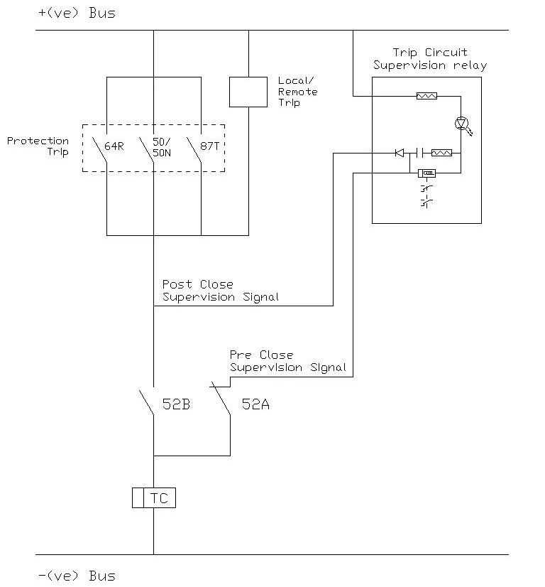
Pre-close supervision, as the name suggests, monitors the trip circuit health before allowing the circuit breaker to close. This is a proactive safety measure that prevents energizing a circuit when the protection system is not ready to respond. Think of it as checking that your car’s brakes are working before you start driving, rather than discovering the problem when you need to stop.
In a pre-close supervision scheme, the supervision relay must confirm that the trip circuit is healthy before the breaker close command can be executed. When an operator initiates a breaker close operation, either locally or remotely, the control system first interrogates the TCS relay.
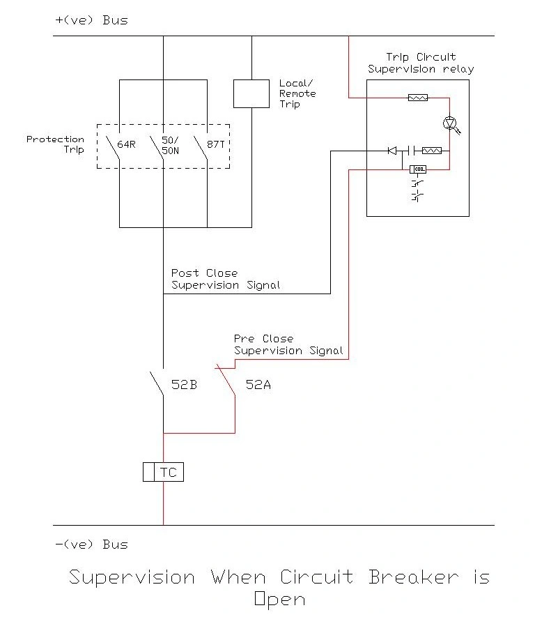
During the pre-close condition, as shown in the figure above, the monitoring current flows from the positive DC supply, through the relay’s supervising circuitry, breaker’s auxiliary NC contact (52A), and the trip coil windings before returning to the negative supply (marked in red color). The TCSR continuously senses this current.
Only if the relay confirms that the trip circuit has acceptable continuity, resistance, and no earth faults will the close command be passed through to the breaker closing mechanism.
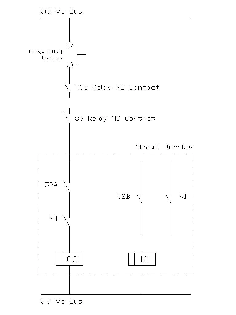
Practically, this is implemented by placing auxiliary NO contacts from the TCS relay in series with the circuit breaker’s closing circuit as shown in the figure above. If the TCS relay detects any abnormality, its contacts remain open, physically preventing the closing coil from being energized.
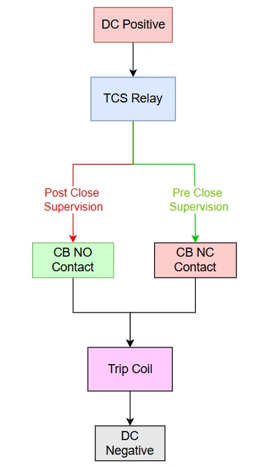
4.2 Post-Close Supervision
When the circuit breaker is closed from the open position, its auxiliary contacts transition to their operational states: the Normally Open (NO) contacts close, and the Normally Closed (NC) contacts open. In this state, the pre-close supervision circuit loses continuity because the NC contact (labeled 52A) opens. To ensure the trip circuit remains healthy and ready to respond to a main circuit fault, a secondary circuit path takes over for post-close supervision.
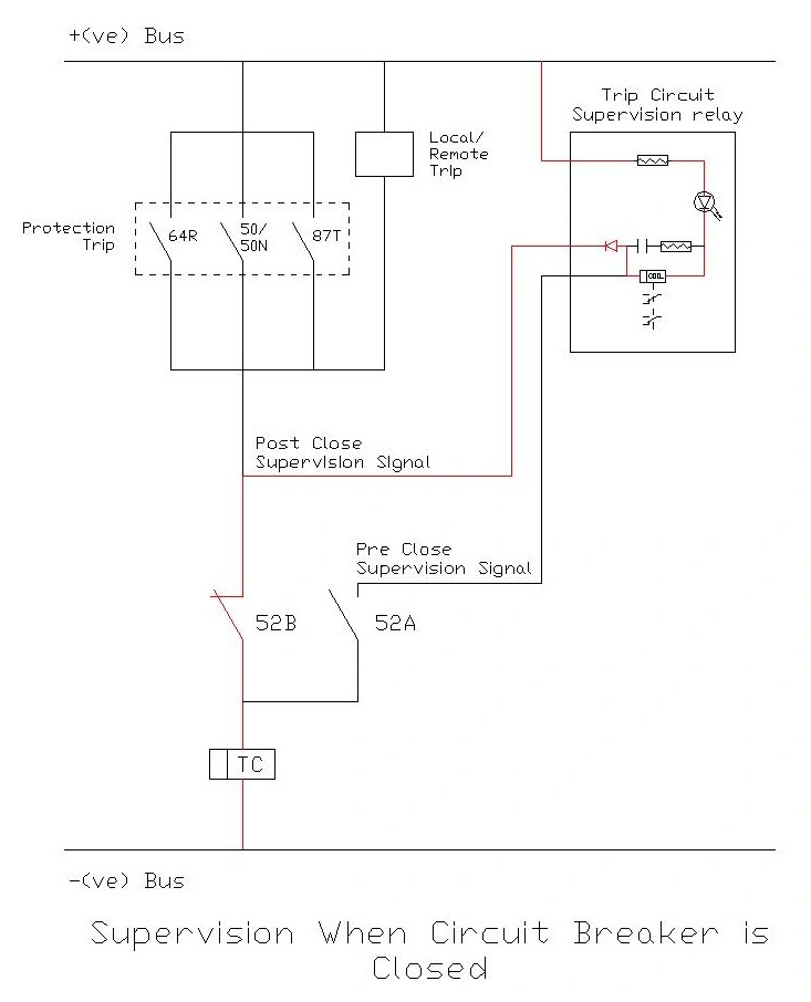
In this post-close condition, the monitoring current flows from the positive DC supply, through the relay’s supervising circuitry, across the breaker’s now-closed auxiliary contact (52B), and through the trip coil windings before returning to the negative supply. The supervision current path marked in red color.
The fundamental advantage of post-close supervision is that it provides real-time monitoring during the period when circuit breaker trip capability is most critical. When a breaker is open, the absence of trip capability is not immediately dangerous since no current is flowing. However, when the breaker is closed and carrying load or fault current, the ability to trip on demand becomes essential for system protection.
Post-close supervision excels in detecting faults that develop gradually over time. Many trip circuit problems do not occur suddenly but develop slowly due to environmental factors, mechanical wear, or component aging. Continuous monitoring catches these developing issues at early stages, allowing planned maintenance rather than emergency repairs. The system also provides confidence to operations personnel that the protection system remains functional throughout extended operating periods.
4.3 Combined Pre-Close and Post-Close Supervision
The most reliable approach combines both pre-close and post-close supervision in a single integrated system. This hybrid approach provides protection throughout the entire breaker operating cycle, from the moment before closing through the entire period of service until the breaker opens again.
In a combined system, the same TCS relay hardware typically handles both functions, but the relay logic distinguishes between the two modes of operation. When the breaker is open, the relay operates in pre-close mode, ready to block closing if trip circuit faults are present. The moment the breaker closes, the relay automatically transitions to post-close mode, beginning continuous health monitoring. When the breaker opens again, the system returns to pre-close mode.
The transition between modes happens seamlessly through auxiliary contacts from the circuit breaker itself. These contacts signal the breaker position to the TCS relay, which adapts its monitoring strategy accordingly.
5. Key Components and Circuit Configuration
A typical Trip Circuit Supervision Relay system consists of several interconnected components that work together to provide comprehensive monitoring.
| Component | Function | Typical Specifications |
|---|---|---|
| Supervision Relay | Monitors current flow and detects abnormalities | Operating voltage: 110V DC / 220V DC |
| Current Limiting Resistor | Limits supervision current to safe levels | Resistance: 10kΩ – 50kΩ, Power rating: 5W – 25W |
| Trip Coil | Actuates circuit breaker mechanism | Operating current: 2A – 5A, Resistance: 50Ω – 200Ω |
| Alarm Circuit | Alerts operators to detected faults | Contact rating: 5A @ 250V AC |
| DC Power Supply | Provides operating voltage | Voltage: 110V DC / 220V DC from station battery |
6. Practical Example: Industrial Substation Application
Let’s walk through a real-world example to see how a Trip Circuit Supervision Relay functions in practice. Consider a medium-voltage industrial substation with a 11kV circuit breaker protecting a critical manufacturing line.
The circuit breaker has a trip coil rated at 220V DC with an operating current of 3 amperes. The minimum current guaranteed to trip the breaker is 2.5 amperes. For this application, we select a TCS relay that maintains a supervision current of 400 milliamperes (16% of minimum trip current).
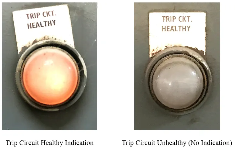
During normal operation, the 400mA supervision current flows continuously through the trip circuit. The TCS relay monitors this current and confirms that all connections are intact and the trip coil resistance is within expected limits. The maintenance team sees a green “healthy” indication on the relay’s front panel, and no alarms are present.
Now, suppose that due to vibration from nearby machinery, a terminal connection in the trip circuit becomes loose over several months. Initially, the connection still makes contact, but with increased resistance. The TCS relay detects that the supervision current has decreased to 350mA due to the higher circuit resistance. While the circuit still has continuity, this change triggers a “pre-alarm” condition.
The maintenance team receives notification through the SCADA system before the connection fails completely. They schedule maintenance during the next available shutdown, tighten the loose connection, and prevent what could have been a complete failure of the trip circuit.
7. Installation and Wiring
When planning the installation, engineers must first verify that the DC supply voltage matches the relay’s rated voltage. Most TCS relays are available in 110V DC or 220V DC versions, corresponding to standard station battery voltages. The current limiting resistor must be calculated based on the trip coil characteristics and selected with adequate power rating.
The physical mounting location of the relay should be in a clean, dry environment with adequate ventilation. While TCS relays are typically ruggedized for substation environments, they should not be exposed to extreme temperatures, excessive dust, or corrosive atmospheres. The relay panel should be easily accessible for periodic inspections and testing.
All connections must be made with properly sized conductors and terminal lugs. Control wiring for trip circuits typically uses 2.5mm² to 4mm² copper conductors with appropriate insulation ratings. Each connection point should be clearly labeled with permanent identification tags showing the circuit function.
Follow these steps to wire the Trip Circuit Supervision (TCS) relay properly.
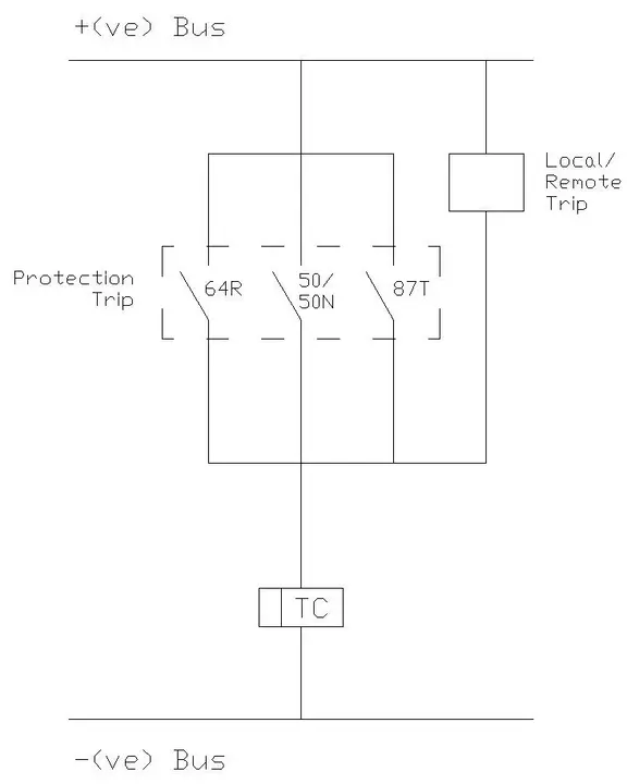
- Positive Supply Connection:
Connect the main positive terminal of the TCS relay directly to the station’s Positive (+ve) DC Bus. This provides the necessary power for the supervision circuitry. - Post-Close Supervision Connection:
Identify the junction point situated after the parallel protection trip contacts (64R, 50/50N, 87T) and before the circuit breaker’s main trip auxiliary contact (labeled 52B). Connect the TCS relay’s “Post Close Supervision Signal” terminal to this specific node. This creates a monitoring loop through contact 52B when the breaker is closed. - Pre-Close Supervision Connection:
Connect the TCS relay’s “Pre Close Supervision Signal” terminal to the circuit breaker’s auxiliary contact labeled 52A. Wire the output of contact 52A directly to the Trip Coil (TC), placing it in parallel with contact 52B. This ensures a supervision path exists through 52A when contact 52B is open (breaker open). - Circuit Completion:
Ensure the Trip Coil (TC) is solidly connected to the Negative (-ve) Bus. Both supervision currents will flow through the TC to the negative return to complete the monitoring loop.
8. Testing and Commissioning Procedures
Testing a Trip Circuit Supervision (TCS) relay is essential to ensure it correctly detects faults without generating nuisance alarms during normal circuit breaker operation. The testing procedure generally involves three key phases: static health checks, fault simulation, and dynamic stability verification.
First, upon applying the rated DC auxiliary voltage and connecting the healthy trip circuit, verify that the relay’s “Healthy” indicator (typically a green LED) illuminates immediately. This confirms that the low-level monitoring current is successfully circulating through the trip coil and auxiliary contacts.
Next, simulate a trip circuit failure by disconnecting a wire at the trip coil terminal or opening a test link. The relay should not trigger an alarm instantly. Instead, verify that it waits for the specified time delay (usually 0.6 seconds) before switching to the “Alarm” state (red LED) and changing the output contact status. This delay is critical for filtering out transient interruptions.
Finally, perform a dynamic test by operating the circuit breaker (Close and Open cycles). The TCS relay must transition smoothly between pre-close and post-close supervision modes without triggering a false alarm. If the alarm activates during breaker operation, the time delay setting may be too short or the wiring logic incorrect.
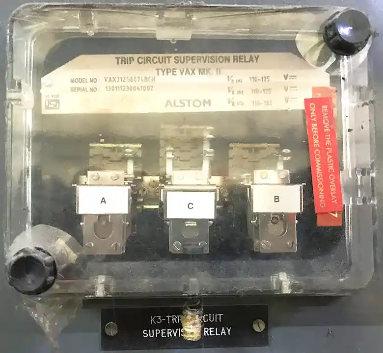
9. Models of TCSR Relays
The market offers several variations of Trip Circuit Supervision Relays from different manufacturers, each designed for specific applications and voltage levels. The major types are differentiated by their rated voltages, contact configurations, and functional capabilities.
9.1 ABB TCS Relay Series
The most widely used industrial standard is the ABB TCS relay family, which represents the benchmark for trip circuit supervision relays globally.
Model: TCS (Standard)
- Rated Voltages: 24V DC, 30V DC, 48V DC, 110-125V AC/DC, 220-250V AC/DC
- Contact Configuration: 1NO + 1NC + 2C/O
- Measuring Current: ~3 mA at rated voltage
- Operating Current Range: 0.3-0.7 mA
- Time Delay: Approximately 0.6 seconds
- Mounting: Flush mounting or Combiflex mounting
- Features: Single channel supervision
Enhanced Models: TCS 121x, TCS 221x, TCS 421x
- Measuring Current: Less than 1 mA
- Channels: Two low-current supervision channels
- External Resistor: Second channel eliminates need for external resistor
- Latched Trip Support: Can accommodate latched trip contacts
- Permanent Trip Support: Can monitor permanent trip circuit (e.g., undervoltage protection)
9.2 Siemens Reyrolle 7PJ13 Trip Circuit Supervision Relay
The Siemens Reyrolle 7PJ13 series offers advanced fault detection capabilities for demanding applications.
Key Specifications:
- Supervision Current Range: 0.7-1.5 mA
- Optocoupler Sensing: Dual optocouplers for redundant detection
- Fault Detection Capabilities: Overcurrent, Earth faults, Phase faults
- Application: Suitable for high-voltage distribution networks and critical circuit breakers
- Advanced Features: Comprehensive fault analysis and recording capabilities
9.3 GE Grid Solutions Trip Circuit Relay (R8010RB Series)
GE’s MVAX series provides sophisticated monitoring for complex protection schemes.
Features:
- Dual Trip Coil Monitoring: Can supervise dual trip coils for redundancy
- Multiple Test Points: Extensive test terminals for commissioning and troubleshooting
- Flag Indication: Mechanical flag for manual verification
- Slugged Drop-off: Prevents false alarms during breaker operation
- Complex Scheme Support: Suitable for systems with multiple trip sources
9.4 Other Manufacturers
- Arteche: VDF, VDJ, and RUT series supervision relays
- GE Vernova: Additional variants for specific applications
- Generic Manufacturers: MRA-PRO-V2 and similar models from Indian and international suppliers
Conclusion
The Trip Circuit Supervision Relay is a critical component of modern electrical protection systems, particularly in high-voltage and critical applications where circuit breaker reliability is important. By continuously monitoring the integrity of the trip circuit and providing immediate alarm notification of any faults, the TCSR prevents the dangerous scenario where a circuit breaker cannot respond to fault conditions.