Circuit breakers are the backbone of electrical protection systems in homes, commercial buildings, and industrial facilities. Among the various types of circuit breakers available in the market, MCB (Miniature Circuit Breaker) and MCCB (Molded Case Circuit Breaker) are the most commonly used devices for protecting electrical circuits from overloads and short circuits. While both devices serve the fundamental purpose of protecting electrical systems, they differ in their construction, ratings, applications, and operational characteristics.
In this technical guide, we will cover the definitions, working principles, specifications, applications, advantages, disadvantages, and key differences between MCB and MCCB. By the end of this article, you will have a thorough understanding of both devices and know exactly when to use each one.
1. What is MCB (Miniature Circuit Breaker)?
1.1 Definition and Overview
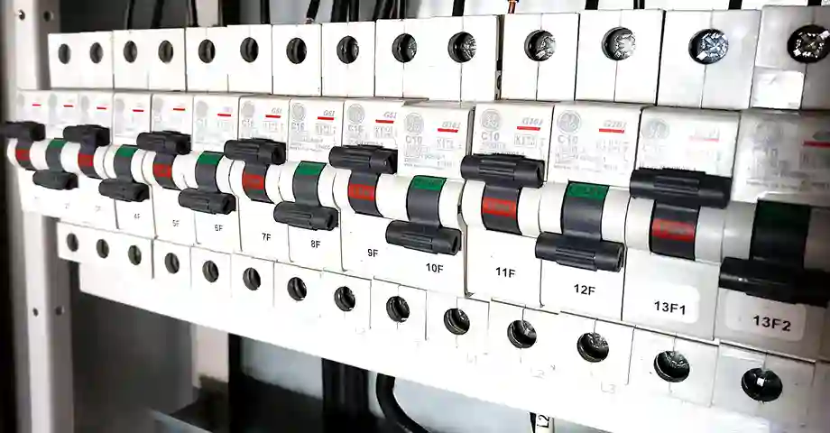
A Miniature Circuit Breaker commonly known as MCB, is a compact electromechanical device designed to automatically switch off an electrical circuit when it detects an overload or short circuit condition. The term “miniature” refers to its small size compared to traditional circuit breakers. This makes it ideal for residential and light commercial applications.
MCBs are designed to handle relatively low current ratings ranging from 0.5 amperes to 125 amperes. They are commonly found in distribution boards of homes, offices, and small commercial establishments. When a fault occurs, the MCB automatically trips and disconnects the power supply to prevent damage to electrical equipment and reducing the risk of fire or electric shock.
1.2 Working Principle of MCB
The working principle of MCB is based on two primary mechanisms: thermal operation and magnetic operation.
The thermal mechanism uses a bimetallic strip that consists of two different metals bonded together. When current flows through the MCB, it generates heat. Under normal operating conditions, this heat is not sufficient to cause any movement in the bimetallic strip. However, when an overload occurs and excess current flows through the circuit. The increased heat causes the bimetallic strip to bend. This bending action triggers the trip mechanism which opens the contacts and disconnects the circuit.
The magnetic mechanism uses an electromagnetic coil or solenoid. When a short circuit occurs a very high current flows through the circuit instantaneously. This high current creates a strong magnetic field in the solenoid which attracts a plunger or armature. The movement of this plunger activates the trip mechanism and opens the contacts immediately.
1.3 Types of MCB Based on Tripping Characteristics
MCBs are classified into different types based on their tripping characteristics or trip curves. The trip curve indicates how the MCB responds to different levels of overcurrent. The most common types are B, C, and D curves, though other curves like K and Z are also available for specific applications.
- Type B MCB trips when the current reaches 3 to 5 times the rated current. This type is most sensitive and is used for resistive loads with low inrush current. Residential applications with lighting circuits, heating elements, and general-purpose socket outlets commonly use Type B MCBs.
- Type C MCB trips when the current reaches 5 to 10 times the rated current. This type is suitable for circuits with moderate inrush current such as those with small motors, fluorescent lighting, and transformers.
- Type D MCB trips when the current reaches 10 to 20 times the rated current. This type is designed for circuits with high inrush current such as large motors, welding machines, transformers, and X-ray equipment.
1.4 Pole Configurations of MCB
MCBs are available in various pole configurations to suit different electrical systems and applications. The pole configuration refers to the number of phases that the MCB can protect simultaneously.
- Single Pole (SP) MCB has one switching contact and protects one phase of a circuit. It is commonly used in single-phase installations where only the live conductor needs to be protected.
- Single Pole with Neutral (SPN) or 1P+N MCB has one switching contact for the live conductor and a neutral link. The neutral is not switched but provides a connection point. This configuration is used when both live and neutral connections are required at the MCB.
- Double Pole (DP) MCB has two switching contacts that operate simultaneously. It switches both the live and neutral conductors at the same time. Double pole MCBs are used for circuits feeding fixed appliances like air conditioners, water heaters, and cookers, where complete isolation is required.
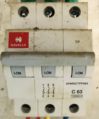
- Three Pole (TP) MCB has three switching contacts for three-phase systems. It protects all three phases of a three-phase circuit and is commonly used in industrial and commercial installations for three-phase loads like motors.
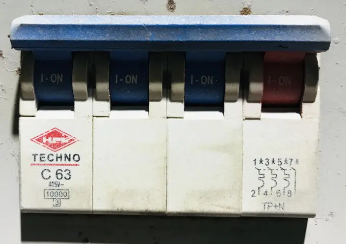
- Four Pole (4P) or Three Pole with Neutral (TPN) MCB has four switching contacts for three-phase systems with neutral. It protects all three phases and the neutral conductor and provides complete isolation for three-phase four-wire systems.
1.5 Current Ratings and Breaking Capacity of MCB
The current rating of an MCB is the maximum continuous current that the device can carry without tripping. MCBs are available in standard current ratings ranging from 0.5A to 125A. Common ratings include 6A, 10A, 16A, 20A, 25A, 32A, 40A, 50A, and 63A.
The breaking capacity or interrupting capacity of an MCB is the maximum fault current that the MCB can safely interrupt without suffering damage. Standard MCBs have breaking capacities ranging from 6kA to 10kA though some high-performance MCBs can handle up to 15kA or 25kA.
2. What is MCCB (Molded Case Circuit Breaker)?
2.1 Definition and Overview
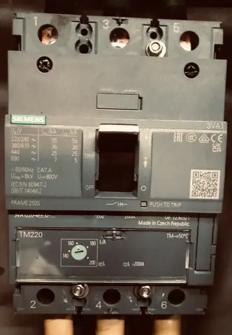
A Molded Case Circuit Breaker commonly known as MCCB, is a type of electrical protection device used to protect electrical circuits from overloads and short circuits in medium to high current applications. The term “molded case” refers to the construction of the breaker where all components are enclosed in a molded insulating case made of glass-polyester or thermoset plastic material.
MCCBs are available in a wide range of current ratings from 16 amperes to 2500 amperes or even higher. They are commonly used in industrial facilities, large commercial buildings, power distribution systems, and applications requiring adjustable protection settings.
The robust construction and higher ratings of MCCBs make them suitable for main distribution panels, motor control centers, and feeder circuits.
2.2 Working Principle of MCCB
The working principle of MCCB is similar to that of MCB utilizing both thermal and magnetic mechanisms for protection. However, MCCBs are designed for higher current applications and often incorporate more advanced trip units with adjustable settings.
The thermal protection mechanism in an MCCB uses a bimetallic contact that responds to heat generated by current flow. When the current exceeds the rated value due to an overload condition the bimetallic element heats up and bends. This bending action releases the latch mechanism and causes the contacts to open and disconnect the circuit. The time taken for tripping depends on the magnitude of the overload current with higher currents causing faster tripping. This is known as the inverse time characteristic.
The magnetic protection mechanism uses an electromagnet that responds to high fault currents during short circuit conditions. When a short circuit occurs the sudden surge of current creates a strong magnetic field in the electromagnet. This magnetic field attracts the trip bar or armature which releases the latch and opens the contacts instantaneously.
In modern MCCBs, electronic trip units are often used instead of or in addition to thermal-magnetic elements. These electronic trip units use current transformers to sense the current flowing through the circuit and microprocessor-based logic to determine when to trip. Electronic trip units offer greater accuracy, adjustability, and additional features like ground fault protection and zone selective interlocking.
2.3 Types of MCCB
MCCBs can be classified based on their trip unit type, mounting configuration, and specific applications.
2.3.1 Based on Trip Unit Type
Based on trip unit type, MCCBs are classified as thermal-magnetic MCCBs and electronic MCCBs.
Thermal-magnetic MCCBs use bimetallic strips and electromagnetic coils for protection. They are simpler, more economical, and suitable for applications where fixed or limited adjustability is acceptable.
Electronic MCCBs use microprocessor-based trip units with current transformers for sensing. They offer wide adjustability, better accuracy, and additional protection functions like ground fault protection, phase imbalance protection, and communication capabilities.
2.3.2 Based on Mounting Configuration
Based on mounting configuration, MCCBs are available as fixed type, plug-in type, and withdrawable or draw-out type.
- Fixed MCCBs are permanently mounted in the enclosure and require disconnection of cables for removal.
- Plug-in MCCBs can be plugged into and removed from a mounting base without disturbing the cable connections.
- Withdrawable MCCBs can be moved between connected, test, and disconnected positions using a racking mechanism which allows testing and maintenance without removing the breaker.
2.3.3 Based on application
Based on application, MCCBs include standard MCCBs for general circuit protection, motor protection MCCBs with characteristics suitable for motor starting currents, and current limiting MCCBs that limit the peak fault current to reduce stress on the electrical system.
2.4 Current Ratings and Breaking Capacity of MCCB
MCCBs are available in frame sizes that determine the maximum current rating. Common frame sizes include 100A frame, 250A frame, 400A frame, 630A frame, 800A frame, and 1600A frame. Within each frame size, various trip unit ratings are available. For example, a 250A frame MCCB might be available with trip units rated at 125A, 160A, 200A, or 250A.
MCCBs have higher breaking capacities compared to MCBs ranging from 16kA to 150kA or even higher at rated voltage.
The short-time withstand rating is another important specification for MCCBs. It indicates the current that the MCCB can carry for a short duration (typically for 0.5 or 1 second) without tripping or sustaining damage. This rating is important for coordinating protection between upstream and downstream devices.
2.5 Adjustable Settings in MCCB
One of the key advantages of MCCBs over MCBs is the availability of adjustable trip settings. These adjustments allow the MCCB to be fine-tuned for the specific application and facilitate coordination with other protective devices in the system.
The thermal or long-time pickup adjustment sets the current level at which the thermal protection begins to operate. This is typically adjustable from 70% to 100% of the rated current in thermal-magnetic MCCBs and from 40% to 100% in electronic MCCBs.
The long-time delay adjustment sets the time delay before the thermal protection trips for a given overload current. This adjustment allows coordination with downstream devices and accommodation of temporary overloads. Electronic MCCBs offer adjustable long-time delay from 2 to 30 seconds at 6 times the pickup current.
The short-time pickup adjustment sets the current level at which the short-time delay protection operates. This is typically adjustable from 2 to 10 times the thermal pickup current.
The short-time delay adjustment sets the time delay for short-time protection, typically adjustable from 0.1 to 0.5 seconds. The combination of short-time pickup and delay settings enables selective coordination where only the breaker closest to the fault trips.
The instantaneous pickup adjustment sets the current level at which the magnetic protection operates without any intentional delay. This is typically adjustable from 2 to 15 times the rated current.
The ground fault pickup and delay adjustments are available in electronic MCCBs with ground fault protection capability. The ground fault pickup is typically adjustable from 20% to 100% of the rated current and the delay is adjustable from 0.1 to 1 second.
3. Key Differences Between MCB and MCCB
3.1 Current Rating Differences
The most fundamental difference between MCB and MCCB is their current rating range.
MCBs are designed for low current applications with ratings ranging from 0.5A to 125A. MCCBs are designed for medium to high current applications with ratings ranging from 16A to 2500A or even higher. They are used as main breakers, feeder breakers, and for protecting large loads in industrial and commercial installations.
3.2 Breaking Capacity Differences
Breaking capacity is another difference between MCB and MCCB.
MCBs have breaking capacities from 6kA to 10kA though some high-performance MCBs can handle up to 25kA. MCCBs have much higher breaking capacities ranging from 16kA to 150kA or higher.
3.3 Size and Physical Dimensions
MCBs are compact devices designed for DIN rail mounting in distribution boards. A single pole MCB typically has a width of 18mm (one module) on a standard 35mm DIN rail. This compact size allows multiple MCBs to be installed in a small distribution board.
MCCBs are larger than MCBs due to their higher current ratings and more robust construction. The size of an MCCB depends on its frame size and current rating. A 100A frame MCCB might measure approximately 100mm x 150mm x 80mm while a 1600A frame MCCB could be several times larger. MCCBs are mounted on panels or frames in dedicated enclosures.
3.4 Adjustability
MCBs generally have fixed trip characteristics determined by their type (B, C, or D curve). Once an MCB is manufactured, its trip characteristics cannot be changed.
MCCBs often feature adjustable trip settings especially in thermal-magnetic and electronic versions. Electronic MCCBs offer the widest range of adjustability with settings for long-time pickup, long-time delay, short-time pickup, short-time delay, instantaneous pickup, and ground fault protection.
3.5 Trip Mechanism
MCBs use basic thermal-magnetic trip mechanisms. The thermal element (bimetallic strip) provides overload protection, and the magnetic element (solenoid) provides short circuit protection. This mechanism is simple, reliable, and adequate for low current applications.
MCCBs may use thermal-magnetic or electronic trip mechanisms. Thermal-magnetic MCCBs are similar to MCBs but are designed for higher currents. Electronic MCCBs use microprocessor-based trip units that offer superior accuracy, wider adjustability, and additional features. Electronic trip units can provide functions like ground fault protection, zone selective interlocking, load monitoring, energy metering, and communication capabilities.
3.6 Remote Operation Capability
MCBs are primarily designed for manual local operation.
MCCBs, especially larger frame sizes are often equipped with motor operators or electrical operators for remote operation. This allows the MCCB to be opened or closed remotely from a control room which is necessary for industrial applications with automated control systems.
3.7 Cost Comparison
MCBs are relatively inexpensive due to their simpler construction and lower ratings.
MCCBs are more expensive than MCBs due their higher ratings, robust construction, and additional features.
3.8 Maintenance Requirements
MCBs are generally considered maintenance-free devices. They are designed for reliable operation throughout their service life without requiring periodic maintenance.
MCCBs, especially larger frame sizes and those in important applications require periodic maintenance. This can include contact inspection and cleaning, lubrication of operating mechanism, testing of trip units, and checking of connections. Electronic MCCBs may also require firmware updates and calibration.
4. Comparative Table: MCB vs MCCB
| Feature | MCB | MCCB |
|---|---|---|
| Full Form | Miniature Circuit Breaker | Molded Case Circuit Breaker |
| Current Rating | 0.5A to 125A | 16A to 2500A+ |
| Breaking Capacity | 6kA to 10kA (up to 25kA) | 16kA to 150kA+ |
| Trip Characteristics | Fixed (B, C, D curves) | Adjustable |
| Trip Unit Type | Thermal-magnetic | Thermal-magnetic or Electronic |
| Size | Compact (DIN rail mount) | Larger (Panel mount) |
| Remote Operation | Limited | Available with motor operator |
| Ground Fault Protection | Separate RCCB required | Integrated (electronic types) |
| Applications | Residential, Light commercial | Industrial, Commercial, Distribution |
| Cost | Lower | Higher |
| Maintenance | Maintenance-free | Periodic maintenance may be required |
| Number of Poles | 1P, 2P, 3P, 4P | 2P, 3P, 4P |
| Mounting | DIN rail | Bolted to panel |
5. Selection Criteria for MCB and MCCB
5.1 Based on Current Rating
The first criterion for selecting between MCB and MCCB is the current rating required. If the load current is below 125A, an MCB may be suitable. For current ratings above 125A, an MCCB is required.
However, even for loads below 125A, an MCCB may be preferred if other factors like breaking capacity, adjustability, or additional features are required.
For example, a 100A feeder circuit could use either a 100A MCB or a 100A MCCB. The choice would depend on the breaking capacity required, whether adjustable settings are needed, and other application-specific requirements.
5.2 Based on Breaking Capacity
The breaking capacity of the circuit breaker must be equal to or greater than the prospective fault current at the installation point. The prospective fault current can be calculated or obtained from the utility company.
For residential installations, the prospective fault current is typically below 6kA, and standard MCBs are adequate.
For commercial and industrial installations, the prospective fault current can be higher (10kA to 50kA or more), requiring MCBs with higher breaking capacities or MCCBs.
5.3 Based on Application Type
The type of application influences the choice between MCB and MCCB.
- For residential final circuits (lighting, sockets, small appliances), MCBs are the standard choice.
- For commercial and industrial feeders and main distribution, MCCBs are typically required.
- For motor protection, MCCBs with adjustable settings are preferred as they can be configured to accommodate motor starting currents.
- For critical applications requiring remote operation or monitoring, MCCBs with motor operators and communication capabilities are selected.
5.4 Based on Coordination Requirements
In complex distribution systems with multiple levels of protection coordination between protective devices is important. Coordination ensures that only the breaker closest to the fault trips minimizing the impact on the rest of the system.
MCCBs with adjustable settings facilitate coordination by allowing the protection characteristics to be fine-tuned. The pickup and delay settings can be adjusted to achieve selective coordination between upstream and downstream devices.
6. Testing and Maintenance
6.1 Testing of MCB
MCBs should be tested periodically to ensure they are functioning correctly. However, since MCBs are generally maintenance-free, extensive testing is not usually required.
Visual inspection should be performed to check for any physical damage, discoloration, or signs of overheating.
Operational testing involves manually switching the MCB on and off to verify smooth operation. If the MCB is stiff or does not operate smoothly, it should be replaced.
Trip testing can be performed using specialized MCB test equipment that injects current to verify the trip characteristics. This is typically done during commissioning or if there is a concern about MCB performance.
6.2 Testing of MCCB
MCCBs require more comprehensive testing and maintenance.
Visual inspection should be performed regularly to check for physical damage, dust accumulation, and signs of overheating.
Operational testing involves manually switching the MCCB on and off (after ensuring safe disconnection from supply). The handle operation should be smooth, and the mechanism should latch properly.
Contact resistance testing measures the resistance across the main contacts using a micro-ohmmeter. High contact resistance indicates worn or contaminated contacts that may need cleaning or replacement.
Insulation resistance testing measures the insulation resistance between phases and to ground using a megger. Low insulation resistance indicates degraded insulation that may lead to faults.
Trip testing verifies that the MCCB trips at the correct current levels and time delays. Primary injection testing uses high current test equipment to inject actual current through the MCCB. Secondary injection testing uses test equipment connected to the trip unit to simulate fault conditions.
For electronic MCCBs, the trip unit settings should be verified and documented. Any communication functions should also be tested.
Maintenance activities for MCCBs may include cleaning of contacts and arc chutes, lubrication of operating mechanism, tightening of terminal connections, and replacement of worn components.
7. Standards and Certifications
7.1 Standards for MCB
MCBs are manufactured according to international standards that specify their requirements for construction, performance, and testing.
- IEC 60898-1 is the international standard for circuit breakers for overcurrent protection for household and similar installations. This standard specifies requirements for MCBs rated up to 125A.
- IEC 60898-2 specifies requirements for MCBs with residual current protection (RCBOs).
- IEC 60947-2 is the standard for low voltage switchgear and controlgear for industrial applications, which includes MCBs used in industrial settings.
- Regional standards like BS EN 60898 (British), DIN VDE 0641 (German), and UL 489 (American) are based on or aligned with the IEC standards.
- MCBs should be certified by recognized testing laboratories like UL, CSA, TUV, or national certification bodies to ensure compliance with relevant standards.
7.2 Standards for MCCB
MCCBs are manufactured according to standards that specify requirements for higher-rated circuit breakers.
- IEC 60947-2 is the primary international standard for circuit breakers used in industrial applications. This standard covers MCCBs along with other types of low voltage circuit breakers.
- UL 489 is the American standard for molded case circuit breakers, which specifies requirements for construction, performance, and testing.
- Regional standards and certifications apply in different countries, and MCCBs should be certified for the market where they will be used.
- MCCBs should also comply with relevant installation standards like IEC 61439 for low voltage switchgear assemblies and national electrical codes.
8. Conclusion
Understanding the difference between MCB and MCCB is essential for anyone involved in electrical engineering, installation, or maintenance. While both devices serve the fundamental purpose of protecting electrical circuits from overloads and short circuits, they are designed for different applications and have distinct characteristics.
9. Frequently Asked Questions (FAQs)
A: Technically, an MCCB can provide the same protection as an MCB for low current circuits. However, MCCBs are larger, more expensive, and may be unnecessary for simple residential circuits. It is more practical to use MCBs for low current applications and MCCBs for higher current applications.
A: Generally, no. If the circuit requires current ratings above 125A or breaking capacities above what MCBs can provide an MCCB is necessary.
A: An MCB may trip repeatedly due to overload (too many devices on the circuit), short circuit (fault in wiring or equipment), ground fault (earth leakage), or a faulty MCB. Identify and address the root cause before resetting the MCB repeatedly.
A: The MCB rating should be selected based on the maximum load current of the circuit and the current-carrying capacity of the cable. The MCB rating should be less than or equal to the cable capacity and greater than or equal to the design load current.
A: MCBs and MCCBs are designed for thousands of operations. An MCB typically lasts 10,000 to 20,000 operations or 10-20 years under normal conditions. MCCBs have similar or longer lifespans depending on the quality and usage conditions. They should be inspected and tested periodically to ensure proper functioning.
A: Electronic MCCBs can have built-in ground fault protection capability. This function can be enabled and configured through the trip unit settings.
A: Breaking capacity is the maximum fault current that the circuit breaker can safely interrupt. Making capacity is the maximum fault current that the circuit breaker can safely close onto.
A: MCCBs are more expensive due to their higher current and voltage ratings, more robust construction, larger contacts and arc chutes, adjustable or electronic trip units, and additional features like remote operation capability.