Power transformers rank among the most expensive and valuable pieces of equipment in any electrical power system. A single large power transformer can cost millions of dollars, and its failure can cause extended outages, equipment destruction, and even fire hazards. Protecting these machines from internal faults is a top priority for power system engineers around the world.
One of the most effective protective devices used for this purpose is the Sudden Pressure Relay (SPR). This device detects a rapid rise in gas or oil pressure inside a transformer tank. Such a rapid pressure rise is usually caused by an internal fault such as an electrical arc or a short circuit between windings.
In this technical guide, we will discuss everything you need to know about the Sudden Pressure Relay, including its construction, working principle, types, applications, comparison with the Buchholz relay, installation practices, testing methods, troubleshooting techniques, and relevant industry standards. Practical examples are included throughout to help you apply these concepts in real-world scenarios confidently.
1. What Exactly Is a Sudden Pressure Relay?
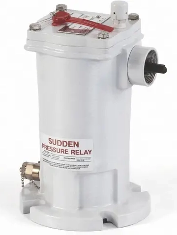
A Sudden Pressure Relay is a mechanical protective device mounted on the transformer tank. Its primary job is to detect any abnormal and rapid increase in pressure inside the transformer. Under normal operating conditions, a transformer may experience slow and gradual changes in internal pressure due to temperature variations and load changes. The SPR is specifically designed to ignore these slow pressure changes. It responds only to a sudden or rapid rate of pressure rise.
This distinction is what makes the Sudden Pressure Relay so valuable. It does not react to normal thermal expansion of oil or gas. Instead, it activates only when the rate of pressure increase exceeds a pre-set threshold. Such a rapid pressure increase is almost always the result of an internal electrical fault. The fault produces gases through the decomposition of insulating oil or solid insulation materials.
Here is a simple example. If an arc occurs between two transformer windings, the extreme heat generated by the arc decomposes the surrounding oil almost instantly. This decomposition produces a large volume of gas in a very short time. The resulting rapid pressure buildup is exactly what the Sudden Pressure Relay is built to detect.
2. ANSI/IEEE Device Number 63
In the ANSI/IEEE C37.2 standard, which defines device function numbers for power system equipment, the number 63 is assigned to a Pressure Relay. More specifically, when this device is used to detect the rate of rise of pressure rather than a static pressure threshold, it is referred to as the Sudden Pressure Relay.
The designation “63” appears on protection single-line diagrams, control schematics, and relay panel nameplates. Engineers use this number to quickly identify the device in project documentation. In some cases, you may also see variations like “63S” (for sudden pressure), “63G” (for gas pressure), or “63B” (for Buchholz relay) to further differentiate between types of pressure-based protection.
Here is a quick reference:
| Designation | Description |
|---|---|
| ANSI Device 63 | Pressure Relay (General) |
| ANSI Device 63 SPR or 63S | Sudden Pressure Relay (Rate of Rise) |
| ANSI Device 63G | Gas Pressure Relay |
| ANSI Device 63 Oil | Oil Pressure Relay |
| ANSI Device 63B | Buchholz Relay |
It is common to find Device 63 working alongside other transformer protective relays such as Device 87 (Differential Relay), Device 51 (Overcurrent Relay), and Device 26 (Temperature Relay) to provide a layered defense against internal faults.
3. Construction and Internal Mechanism
The Sudden Pressure Relay is a relatively simple yet highly effective mechanical device. Its construction is designed to respond to the rate of pressure change rather than the absolute level of pressure. The following sections examine its main components and operating mechanism in detail.
3.1 Main Components
3.1.1 Pressure-Sensing Diaphragm or Bellows
This is the primary sensing element. It is a flexible metallic membrane or bellows assembly that responds to pressure changes inside the transformer tank. One side of the diaphragm is exposed to the transformer’s internal gas or oil space. The other side is connected to a sealed reference chamber.
3.1.2 Equalizing Orifice (Bleed Hole)
This is a small hole or calibrated orifice that connects the two sides of the diaphragm. It allows slow, gradual pressure changes to equalize across the diaphragm. The size of this orifice determines the relay’s sensitivity. A slow pressure rise caused by normal temperature changes passes through this orifice and equalizes, so the diaphragm does not deflect. A rapid pressure rise, however, cannot equalize fast enough through the tiny orifice. This causes the diaphragm to deflect.
3.1.3 Microswitch or Contact Assembly
The diaphragm actuates a microswitch when it deflects beyond a set threshold. This switch closes or opens a set of electrical contacts. These contacts are wired into the transformer’s protection circuit to initiate a trip or alarm signal.
3.1.4 Housing and Mounting Flange
The relay is housed in a rugged, sealed enclosure designed to be mounted directly on the transformer tank wall. The mounting flange provides a gas-tight seal between the relay and the transformer’s internal gas space.
3.1.5 Test and Reset Mechanism
Most modern SPR designs include a manual test button and a reset mechanism. The test button allows field engineers to simulate a pressure rise and verify that the relay contacts operate correctly. The reset mechanism returns the relay to its normal position after it has tripped.
3.2 How the Mechanism Works — Step by Step
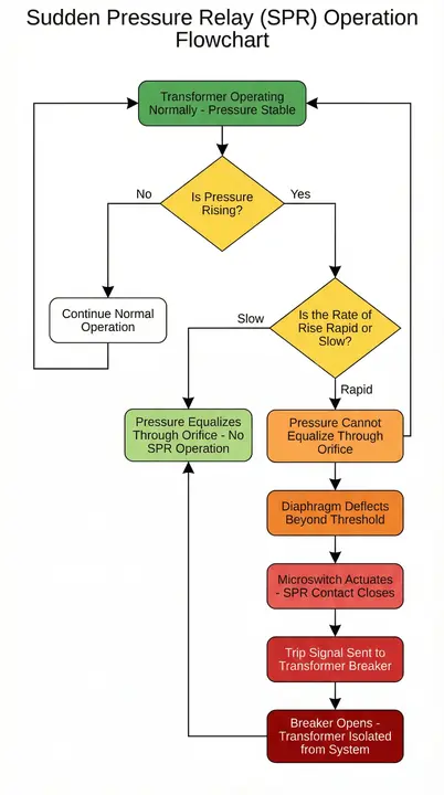
Step 1: The transformer operates under normal conditions. The oil inside heats up slowly as the load increases. This causes a gradual rise in internal pressure.
Step 2: The gas on the sensing side of the diaphragm pushes through the equalizing orifice to the reference side. The pressure on both sides remains balanced. The diaphragm stays in its neutral position, and the relay contacts remain open.
Step 3: An internal fault occurs — for example, an arc between windings. The arc generates an enormous amount of heat in milliseconds.
Step 4: The oil near the arc decomposes rapidly and produces combustible gases. This creates a very sudden spike in pressure.
Step 5: The gas pressure on the sensing side of the diaphragm rises so quickly that it cannot equalize through the small orifice. The diaphragm deflects sharply.
Step 6: The deflection trips the microswitch, and the relay contact closes. The trip signal is sent to the transformer breaker, and the transformer is disconnected from the system.
This entire operation happens within milliseconds to a few tens of milliseconds, making the SPR one of the fastest-acting mechanical protective devices available for transformers.
4. Working Principle in Detail
The operating principle of the Sudden Pressure Relay is based on the rate of rise of pressure inside the transformer tank. The mechanism described in the Construction section above explains how the equalizing orifice allows slow pressure changes to pass through and balance the diaphragm, while rapid pressure changes cause the diaphragm to deflect and actuate the trip contact. This section provides additional technical detail on the operating conditions.
4.1 Normal Operation
During normal operation, the transformer’s internal oil temperature changes slowly over minutes or hours. A change in oil temperature leads to a change in oil volume. This in turn leads to a change in the gas space pressure above the oil in sealed transformers, or in the oil pressure itself. These gradual changes equalize through the orifice, and the relay does not operate.
4.2 Fault Condition
An internal fault such as a turn-to-turn short circuit, a phase-to-ground fault, or an inter-winding fault produces intense localized heating from the fault arc. This heating causes rapid thermal decomposition of the transformer oil and cellulose insulation. Gases such as hydrogen, methane, ethylene, and acetylene are generated in large quantities almost instantaneously.
The sudden generation of these gases causes a sharp spike in pressure inside the transformer tank. This rate of pressure rise far exceeds the capacity of the equalizing orifice to balance the pressure across the diaphragm. The pressure differential increases, the diaphragm deflects, and the contact mechanism actuates to generate a trip signal.
4.3 Sensitivity and Set Points
The sensitivity of the SPR is determined by the size of the equalizing orifice and the spring tension on the diaphragm. Manufacturers calibrate these parameters so that the relay ignores pressure changes below a certain rate and responds only to pressure changes above a specific rate of rise.
A common set point for the rate of rise is around 3 to 7 psi per second (approximately 20 to 50 kPa per second), depending on the manufacturer and the transformer application. Some models allow field adjustment of the sensitivity.
Note: These values are approximate and vary by manufacturer and application. Always refer to the specific relay’s instruction manual for exact set points and calibration procedures.
5. Types of Sudden Pressure Relay
There are primarily two types of SPR used in practice, based on the medium they sense.
5.1 Gas Space Sudden Pressure Relay
This type is mounted on the upper portion of the transformer tank, where it is exposed to the gas space (nitrogen blanket) above the oil level. It detects the rate of rise of gas pressure in this space. This is the most common type used in sealed transformers that use a nitrogen gas blanket system and do not have conservator tanks.
Example: A sealed 138 kV power transformer with a nitrogen gas blanket system uses a gas space SPR mounted on the tank cover. If an internal arc generates gases, the SPR detects the rapid pressure increase in the gas space and trips the transformer breaker.
5.2 Oil Space Sudden Pressure Relay
This type is mounted below the oil level on the transformer tank wall. It directly senses the rate of rise of oil pressure. Some designs use this approach because the pressure wave from a fault travels through the oil faster than through the gas space. This can provide even faster fault detection in some cases.
5.3 Selecting the Right Type
The choice between gas space and oil space SPR depends on the transformer design. Sealed transformers with nitrogen gas blankets use gas space SPRs. Transformers with conservator tanks may use oil space SPRs or may rely on a Buchholz relay instead. In many cases, both devices are installed together for complementary protection.
6. Applications of Sudden Pressure Relay
The Sudden Pressure Relay is used in a variety of power system equipment. Here are the primary applications.
6.1 Power Transformers
The most common application is in large power transformers rated 10 MVA and above. These transformers are expensive and carry high fault energy. An internal fault left undetected for even a fraction of a second can cause severe damage, including tank rupture and fire. The SPR provides fast-acting backup or sometimes primary protection for these transformers.
6.2 Load Tap Changers (LTCs)
Load tap changers are mechanical switching devices inside transformers that adjust the turns ratio under load. They have their own oil compartment. Arcing contacts inside the LTC can occasionally fail, producing a sudden gas buildup. An SPR mounted on the LTC compartment can detect this fault and trip the transformer to prevent further damage.
6.3 Reactors
Shunt reactors and series reactors used for reactive power compensation and system stability also use oil-filled tanks. These reactors are subject to similar internal faults as transformers. SPRs are used on reactor tanks to provide rapid fault detection.
6.4 Phase-Shifting Transformers
Phase-shifting transformers, also called phase angle regulators, are complex devices that may have multiple tank compartments. SPRs can be installed on each compartment to provide independent pressure protection.
6.5 Instrument Transformers
Some large oil-filled current transformers (CTs) and voltage transformers (VTs) used at high voltage levels also employ sudden pressure protection.
7. Sudden Pressure Relay vs. Buchholz Relay
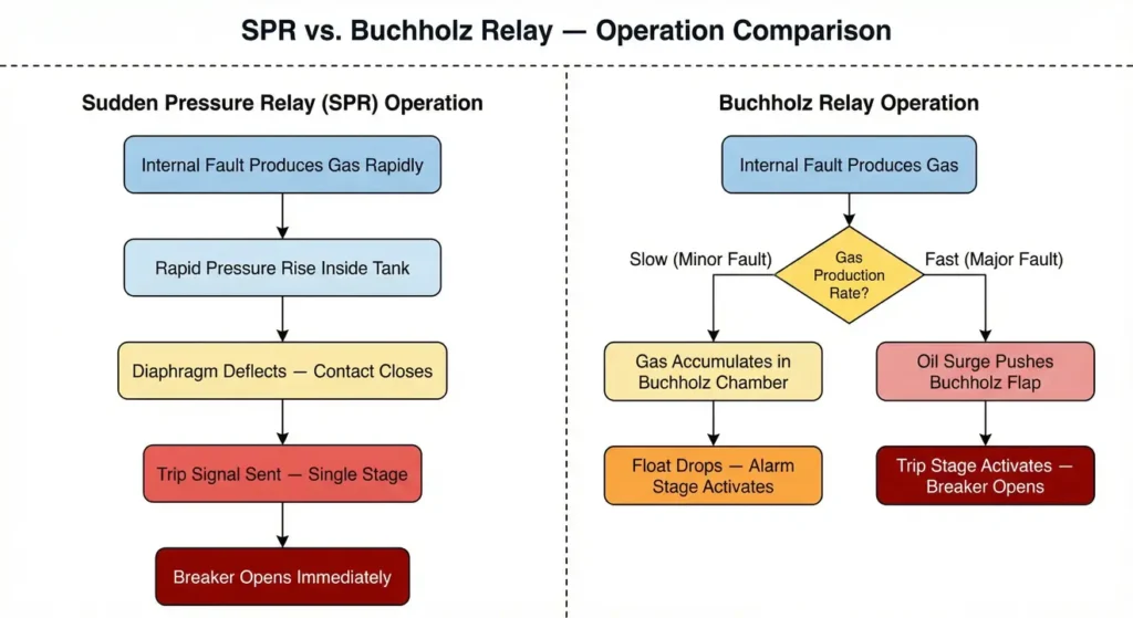
Both the Sudden Pressure Relay and the Buchholz Relay are used for transformer protection. Both respond to gas generation caused by internal faults. However, they differ in several important ways.
7.1 Buchholz Relay
The Buchholz Relay is installed in the pipe connecting the transformer main tank to the conservator tank. It operates on two principles. First, it detects the accumulation of gas, which indicates minor faults. Second, it detects a sudden surge of oil flow, which indicates major faults. The Buchholz relay requires a conservator-type tank design to function.
7.2 Comparison Table
| Feature | Sudden Pressure Relay (SPR) | Buchholz Relay |
|---|---|---|
| Mounting Location | Directly on the transformer tank | In the pipe between tank and conservator |
| Transformer Design | Sealed (nitrogen blanket) or conservator | Conservator type only |
| Sensing Principle | Rate of rise of pressure | Gas accumulation and oil surge |
| Speed of Operation | Very fast (milliseconds) | Fast for surge; slow for gas accumulation |
| ANSI Device Number | 63S or 63 SPR | 63B |
| Gas Sampling | Not possible | Gas can be collected and analyzed |
| Number of Stages | Usually single stage (trip) | Two stages (alarm and trip) |
7.3 Selecting Between the Two
Sealed transformers without conservators cannot use Buchholz relays because there is no conservator pipe. In such cases, the SPR is the primary gas and pressure-based protection device. Transformers with conservator tanks can use both devices. In fact, many large conservator-type transformers use a Buchholz relay for gas accumulation detection and an SPR for rapid fault detection. The two devices provide complementary protection, and using both together offers a stronger defense against internal faults than using either one alone.
8. Relationship Between SPR and Pressure Relief Device (PRD)
The Sudden Pressure Relay should not be confused with the Pressure Relief Device (PRD), which is another protective device found on transformer tanks.
The PRD is a mechanical pressure relief valve that opens when the internal tank pressure exceeds a fixed static threshold. It does not measure the rate of pressure rise. Instead, it acts as a last line of defense to prevent catastrophic tank rupture if the internal pressure reaches a dangerous level.
Here is how the two devices work together in a protection sequence:
- Step 1: An internal fault occurs and generates gases rapidly.
- Step 2: The SPR detects the rapid rate of pressure rise and sends a trip signal to the breaker. The breaker opens, and the transformer is disconnected from the system. The fault arc extinguishes, and the pressure stops rising.
- Step 3 (Failure scenario): If the SPR fails to operate, or if the breaker fails to open, the fault continues. Pressure inside the tank keeps rising.
- Step 4: The PRD opens when the static pressure exceeds its set point (for example, 10 to 15 psi). This releases gas and oil to the outside to prevent the tank from rupturing.
Both devices are part of a complete transformer pressure protection strategy. The SPR provides electrical tripping to isolate the fault early. The PRD provides mechanical pressure relief as a backup to prevent physical tank failure.
9. Protection Coordination with Other Devices
The Sudden Pressure Relay does not operate in isolation. It is part of a coordinated transformer protection scheme that includes several other devices. Here is how the SPR coordinates with the most common transformer protection relays.
9.1 Differential Relay (Device 87)
The differential relay is the primary electrical protection for most power transformers. It compares the current entering the transformer with the current leaving it. If there is a mismatch beyond a set threshold, it trips the transformer breakers. The SPR and the differential relay are wired to trip the same breakers. Either device can independently initiate a trip.
For low-energy arcing faults that produce minimal current change, the SPR may detect the fault faster than the differential relay because it senses gas generation rather than fault current.
9.2 Overcurrent Relay (Device 51)
The overcurrent relay provides backup protection with time-graded coordination. It operates on a time-current characteristic and is set to coordinate with downstream protective devices. The SPR does not have a time delay and trips the breaker immediately upon detection of a rapid pressure rise.
9.3 Temperature Relay (Device 26)
The temperature relay monitors the winding and oil temperature of the transformer. It provides alarm and trip functions for overtemperature conditions. The temperature relay protects against overloading and cooling system failures. The SPR protects against internal electrical faults. These are different failure modes, and both devices are needed for complete protection.
9.4 Buchholz Relay (Device 63B)
As discussed earlier, the Buchholz relay and the SPR can both be installed on conservator-type transformers. The Buchholz relay provides an alarm stage for minor faults with slow gas generation. The SPR provides a fast trip for major faults with rapid pressure rise. Together, they cover a wide range of fault severity levels.
10. Modern Digital Monitoring Alternatives
Traditional mechanical SPRs have been in service for decades and remain widely used due to their simplicity and reliability. However, modern transformer monitoring systems now offer digital pressure sensing as part of an integrated monitoring platform.
Companies such as Qualitrol, GE, and ABB offer digital transformer monitoring systems that combine pressure sensing with other measurements. These include oil temperature, winding temperature, dissolved gas levels, moisture content, and load current. These systems can provide continuous pressure trending and rate-of-rise analysis. They can also store historical data and send alerts through SCADA or other communication systems.
11. Installation and Mounting
Proper installation of the Sudden Pressure Relay is a requirement for reliable operation. Here are the main considerations.
11.1 Mounting Location
The relay must be mounted in a location that provides direct exposure to the transformer’s internal gas or oil space. For gas space SPRs, this is usually on the top of the tank or on an upper side panel above the oil level. For oil space SPRs, the mounting is on the side of the tank below the minimum oil level.
11.2 Orientation
The relay must be mounted in the correct orientation as specified by the manufacturer. Incorrect orientation can affect the diaphragm’s response and may cause false trips or failure to operate during a real fault.
11.3 Isolation Valve
Many installations include an isolation valve between the relay and the transformer tank. This valve allows the relay to be isolated for maintenance or testing without draining the transformer oil. The valve must be fully open during normal operation.
A common operational mistake is leaving this valve closed after maintenance. This makes the SPR completely non-functional. Proper procedures and checklists should be in place to prevent this error. Some utilities apply cable ties or lock-open mechanisms on the valve handle to provide a visual indication that the valve is in the correct position.
11.4 Wiring
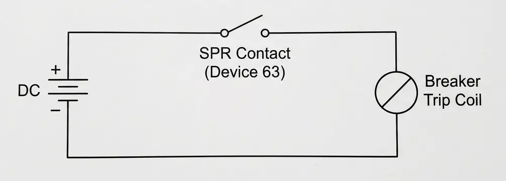
The SPR contacts are wired into the transformer protection and control circuit. The trip contact is connected to the transformer breaker trip circuit. Some SPRs also have an alarm contact that can be wired to a SCADA system or annunciator panel. The contact wiring should follow the relay manufacturer’s recommendations and the substation’s protection design philosophy.
11.5 Grounding and Shielding
The relay’s wiring should be properly shielded and grounded to prevent electromagnetic interference (EMI) from causing false operations. This is especially important in high-voltage substations where strong electromagnetic fields are present.
12. Testing and Commissioning
Regular testing of the Sudden Pressure Relay is a must to confirm that it will operate correctly during a fault. Here are the common testing methods.
12.1 Factory Acceptance Test (FAT)
The manufacturer performs calibration and functional testing before shipping the relay. This includes verifying the rate-of-rise sensitivity, contact operation, and mechanical integrity.
12.2 Field Commissioning Test
During transformer commissioning, the SPR is tested on-site. The procedure includes the following steps:
- Visual Inspection: Check the relay for physical damage, correct mounting, and proper orientation. Verify that the isolation valve is fully open.
- Contact Continuity Test: Use a multimeter to verify the continuity of the relay contacts in both the normal and operated states.
- Functional Test Using Test Button: Most SPR models have a built-in test button or test port. Pressing the test button or applying test pressure simulates a rapid pressure rise and should cause the relay contacts to change state. Verify that the trip signal reaches the transformer breaker trip coil.
- Pressure Test (if applicable): Some testing procedures involve applying a controlled pressure pulse to the relay’s sensing port using a hand pump or a calibrated pressure source. This test verifies the relay’s sensitivity and operating threshold.
- Insulation Resistance Test: Measure the insulation resistance of the relay contacts to verify that there is no degradation.
- Wiring Verification: Trace and verify all wiring connections from the relay to the trip coil and alarm circuits.
12.3 Periodic Maintenance Testing
The SPR should be tested periodically as part of the transformer’s maintenance program. A common interval is every 1 to 3 years, depending on the utility’s maintenance policy and regulatory requirements. The periodic test usually includes the functional test, contact resistance measurement, and visual inspection.
13. Advantages of Using a Sudden Pressure Relay
The SPR offers several notable benefits for transformer protection.
13.1 Very Fast Response Time
The SPR can detect and respond to an internal fault within milliseconds. This speed can be faster than electrical relays like differential relays, especially for certain types of faults. Low-energy arcing faults that produce minimal current change but generate gases rapidly are a good example.
13.2 Independent of Electrical Measurements
The SPR does not rely on current transformers (CTs) or voltage transformers (VTs). It operates purely on mechanical pressure sensing. This means it is immune to CT saturation, VT fuse failures, and other electrical measurement errors that can affect electronic relays.
13.3 Simple and Reliable
The device has few moving parts and a straightforward operating mechanism. It does not require an external power supply for sensing, although the trip circuit does need DC power. Its simplicity contributes to high reliability over long service periods.
13.4 Effective for Low-Level Faults
Some internal faults, such as partial discharges or low-energy arcing between adjacent turns, may not produce enough fault current to be detected by overcurrent or differential relays. However, these faults do generate gases and pressure changes that the SPR can detect.
13.5 Suitable for Sealed Transformers
For sealed transformers that do not have conservator tanks, the SPR provides a function similar to the Buchholz relay. It fills a protective gap that would otherwise exist in the protection scheme.
14. Limitations of the Sudden Pressure Relay
Despite its advantages, the SPR has some limitations that engineers should be aware of.
14.1 Cannot Identify Fault Type or Location
The SPR only tells you that a rapid pressure rise occurred. It does not provide information about the nature of the fault, its location within the transformer, or the gases produced. Additional investigation such as dissolved gas analysis is needed after an SPR operation.
14.2 Mechanical Device with Wear
Over many years, the mechanical components including the diaphragm, springs, and contacts can degrade. Regular testing and maintenance are required to maintain reliability.
14.3 Single-Shot Device
Once the SPR trips, it must be manually reset. In some designs, it resets automatically after the pressure equalizes. It does not provide continuous monitoring or trending information.
14.4 No Gas Sampling Capability
Unlike the Buchholz relay, the SPR does not collect gas samples. Gas sampling and analysis provide valuable diagnostic information about the type and severity of the internal fault. This capability is not available with the SPR alone.
15. Prominent Manufacturers
Several manufacturers produce Sudden Pressure Relays for the power industry. Some of the most well-known include:
Qualitrol (now part of Fortive): The Qualitrol Model 900 (gas space) and Model 910 (oil space) series are among the most widely used SPRs in North America. They are available in multiple configurations for different transformer designs.
ABB: ABB offers sudden pressure protection devices as part of their transformer monitoring and protection product line, including devices within their TEC transformer electronics portfolio.
Siemens: Siemens provides SPR devices integrated into their transformer protection solutions.
Maschinenfabrik Reinhausen (MR): MR manufactures tap changer protection devices that include sudden pressure sensing for LTC compartments, including their MSENSE and ETOS monitoring systems.
Weidmann Electrical Technology: Weidmann offers transformer accessories including pressure relief and sudden pressure devices.
16. Standards and References
The following standards and references are relevant to the design, application, and testing of Sudden Pressure Relays:
- ANSI/IEEE C37.2 – Standard for Electrical Power System Device Function Numbers and Contact Designations (defines Device 63).
- IEEE C57.12.00 – Standard for General Requirements for Liquid-Immersed Distribution, Power, and Regulating Transformers.
- IEEE C57.12.90 – Standard Test Code for Liquid-Immersed Distribution, Power, and Regulating Transformers.
- IEEE C57.91 – Guide for Loading Mineral-Oil-Immersed Transformers and Step-Voltage Regulators.
- IEEE C57.104 – Guide for the Interpretation of Gases Generated in Mineral-Oil-Immersed Transformers (relevant for post-SPR-operation diagnostics).
- NETA MTS – Standard for Maintenance Testing Specifications for Electrical Power Equipment and Systems (includes testing recommendations for SPRs).
17. Conclusion
The Sudden Pressure Relay is a proven, reliable, and fast-acting protective device that plays an important role in transformer protection schemes. Its ability to detect internal faults through rapid pressure sensing makes it an indispensable tool for power system engineers. The ANSI Device Number 63 relay operates on a simple mechanical principle, yet it provides a level of fault detection that complements and sometimes outperforms electronic protection relays.
Engineers should give proper attention to the installation, testing, and maintenance of the SPR to keep it in reliable working condition at all times. A well-maintained SPR can mean the difference between a controlled transformer trip and a catastrophic transformer failure resulting in equipment destruction, fire, and extended outages.
18. Frequently Asked Questions (FAQs)
A Sudden Pressure Relay is a mechanical protective device mounted on a transformer tank. It detects a rapid rate of rise in internal gas or oil pressure, which indicates an internal fault such as an electrical arc. Upon detection, it sends a trip signal to disconnect the transformer from the power system.
The ANSI/IEEE device function number for a Sudden Pressure Relay is 63. It may also appear as 63S or 63 SPR to distinguish it from other pressure-based devices.
The Buchholz Relay is installed in the pipe between the transformer tank and the conservator. It detects gas accumulation for minor faults and oil surges for major faults. The Sudden Pressure Relay is mounted directly on the transformer tank and detects the rate of rise of pressure.
Yes. False trips can occur due to rapid load changes, external pressure disturbances, mechanical vibrations, or electromagnetic interference.
Most utilities test the SPR every 1 to 3 years as part of the transformer’s periodic maintenance program. The test usually includes a functional test using the built-in test button, contact resistance measurement, and visual inspection.
An SPR operation indicates that a rapid pressure rise occurred inside the transformer tank. This is usually caused by gas generation from the thermal decomposition of insulating oil or solid insulation. The decomposition is caused by an internal electrical fault such as an arc, spark, or localized overheating.
No. The SPR detects faults that produce gas or pressure changes inside the tank. It is highly effective for arcing faults and turn-to-turn faults.
The equalizing orifice is a small calibrated hole that connects the sensing side and the reference side of the diaphragm. It allows slow pressure changes to pass through and balance the diaphragm, preventing the relay from operating during normal conditions.
For gas space SPRs, the relay is mounted on the top of the tank or on an upper side wall above the oil level. For oil space SPRs, the relay is mounted on the side of the tank below the minimum oil level.
The sensing mechanism of the SPR does not require an external power supply. It is purely mechanical. However, the trip circuit that carries the signal from the relay contact to the breaker trip coil requires a DC control power supply, just like any other protective relay trip circuit.
The SPR detects the rate of rise of pressure and sends an electrical trip signal to the breaker. The PRD is a mechanical valve that opens at a fixed static pressure threshold to physically release gas and oil from the tank. The SPR acts first to isolate the transformer electrically. The PRD acts as a last resort to prevent tank rupture if the fault is not cleared by the SPR and breaker.
Yes. Although the SPR is most commonly associated with sealed transformers, it can also be installed on conservator-type transformers.