Power systems are designed to operate under balanced and stable conditions. However, faults occur in electrical networks due to insulation failure, equipment malfunction, lightning strikes, falling trees, and many other causes. These faults disrupt the normal flow of current and can cause severe damage to equipment, endanger human life, and lead to widespread power outages. Every electrical engineer must have a solid grasp of fault types to design protective systems effectively.
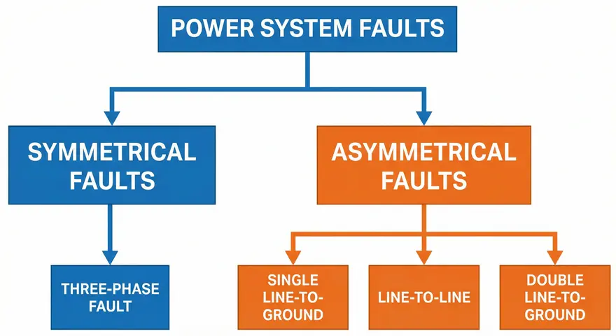
Faults in power systems are broadly classified into two categories: symmetrical faults and asymmetrical faults. This classification is based on how the fault affects the three phases of the power system. A symmetrical fault affects all three phases equally and simultaneously. An asymmetrical fault, on the other hand, affects the phases unequally.
In this technical guide, we will discuss everything you need to know about symmetrical and asymmetrical faults, including their definitions, types, causes, characteristics, analysis methods, ANSI codes, effects on power systems, calculation techniques, and protective strategies. Practical examples are included throughout to help you apply these concepts in real-world scenarios confidently.
1. What is a Fault in a Power System?
A fault in an electrical power system is any abnormal condition that causes current to flow through an unintended path. Under normal conditions, current flows from the source through the conductors to the load and returns through the neutral or ground path in a controlled manner. A fault disrupts this normal condition.
Faults can occur at any point in the power system. They can happen at generators, transformers, transmission lines, distribution feeders, busbars, or even at the load end. The magnitude of fault current depends on the system voltage, the impedance of the fault path, and the location of the fault within the network.
Fault currents are usually much larger than normal load currents. For example, a distribution feeder that normally carries 400 amperes might experience fault currents exceeding 10,000 amperes during a short circuit. These high currents generate extreme heat and electromagnetic forces that can destroy equipment within milliseconds if not interrupted quickly.
Protective devices such as circuit breakers, fuses, and relays are installed throughout the power system to detect and isolate faults rapidly. The design and coordination of these protective devices require accurate fault analysis. This is where the classification of faults into symmetrical and asymmetrical types becomes directly relevant.
2. Classification of Faults: Symmetrical vs. Asymmetrical
Faults in a three-phase power system are classified based on the number of phases involved and the nature of the fault. The two main categories are symmetrical faults and asymmetrical faults.
- Symmetrical faults involve all three phases of the system equally. The fault condition is balanced, meaning the magnitude and phase angle relationships between the three phases remain uniform during the fault. The three-phase short circuit is the only type of symmetrical fault.
- Asymmetrical faults involve one or two phases and do not affect all three phases equally. The fault condition is unbalanced, creating unequal currents and voltages in the three phases. Asymmetrical faults include single line-to-ground faults, line-to-line faults, and double line-to-ground faults.
The majority of faults that occur in real power systems are asymmetrical. Studies and field data show that approximately 70-80% of all faults are single line-to-ground faults. Symmetrical three-phase faults are the rarest, accounting for only about 2-5% of all faults. However, three-phase faults produce the highest fault current magnitudes in most cases, making them the most severe from an equipment rating perspective.
3. Symmetrical Faults
3.1 Definition
A symmetrical fault is a balanced fault condition in which all three phases of the power system are affected equally and simultaneously. The most common example is a three-phase short circuit, where all three phase conductors come into contact with each other. A three-phase-to-ground fault, where all three phases are simultaneously connected to ground, is also a symmetrical fault.
During a symmetrical fault, the system remains balanced. The current magnitudes in all three phases are equal, and the phase angles between them maintain their 120-degree separation. This balanced nature simplifies the analysis considerably because the system can be analyzed using a single-phase equivalent circuit.
3.2 ANSI Fault Code
The three-phase fault is designated as “3P” or “3Ø” fault in power system studies. In terms of ANSI device numbers for protective relays, the relevant codes include:
- ANSI 50 – Instantaneous Overcurrent Relay (used for fault detection)
- ANSI 51 – Time Overcurrent Relay (used for fault detection with time delay)
- ANSI 87 – Differential Protection Relay (used for transformer and generator protection against internal faults)
3.3 Characteristics of Symmetrical Faults
Symmetrical faults have several distinct characteristics that set them apart from asymmetrical faults.
Equal phase currents: All three phases carry fault currents of equal magnitude. If phase A carries 15,000 amperes of fault current, phases B and C also carry 15,000 amperes each.
Balanced voltage depression: The voltage drops equally across all three phases at the fault location. At the exact point of a bolted three-phase fault, the voltage on all three phases drops to zero simultaneously.
Highest fault current magnitude: In most power systems, the three-phase fault produces the highest fault current compared to other fault types. This is because the fault impedance is at its minimum when all three phases are shorted together.
Simplified analysis: Because the system remains balanced during a symmetrical fault, it can be analyzed using positive-sequence impedance only. Negative-sequence and zero-sequence networks are not needed for symmetrical fault calculations.
3.4 Causes of Symmetrical Faults
Symmetrical faults are rare but do occur under certain conditions. Lightning strikes can simultaneously affect all three phases on transmission lines, especially when the conductors are closely spaced. Equipment failures inside switchgear or transformers can create three-phase short circuits internally. Human error during maintenance, such as accidentally leaving grounding clamps on all three phases, can also cause symmetrical faults. Mechanical failures like tower collapse can bring all three conductors into contact simultaneously.
3.5 Example of Symmetrical Fault Calculation
Consider a simple power system with a generator rated at 100 MVA, 11 kV, with a subtransient reactance (X”d) of 0.2 per unit. Calculate the three-phase fault current at the generator terminals.
Step 1: The base values are 100 MVA and 11 kV.
Step 2: The base current is calculated as:
\(I_{base} = \dfrac{100,000,000}{(\sqrt{3} \times 11,000)} = 5,249 A\)
Step 3: The per-unit fault current is:
\(I_{fault (pu)} =\dfrac{V}{X^”_d} = \dfrac{1.0}{0.2} = 5.0 \,\text{per unit}\)
Step 4: The actual fault current is:
\(I_{fault} = 5.0 \times 5,249 = 26,245 A\)
This means the generator would supply approximately 26,245 amperes during a three-phase fault at its terminals. Circuit breakers and other protective equipment at this location must be rated to interrupt this level of current safely.
4. Asymmetrical Faults
4.1 Definition
An asymmetrical fault is an unbalanced fault condition in which the three phases of the power system are not affected equally. The current magnitudes and phase angles differ across the three phases during this type of fault. Asymmetrical faults are far more common than symmetrical faults in real power systems.
The analysis of asymmetrical faults is more complex than symmetrical faults because the system becomes unbalanced. A special mathematical technique called the method of symmetrical components, developed by Charles Fortescue in 1918, is used to analyze these unbalanced conditions. This method decomposes the unbalanced system into three balanced systems: positive-sequence, negative-sequence, and zero-sequence components.
4.2 Types of Asymmetrical Faults
There are three main types of asymmetrical faults:
- Single Line-to-Ground Fault (SLG or L-G)
- Line-to-Line Fault (L-L)
- Double Line-to-Ground Fault (DLG or L-L-G)
Each type has different characteristics, different fault current magnitudes, and different effects on the power system. Let us examine each type in detail.
5. Single Line-to-Ground Fault (SLG)
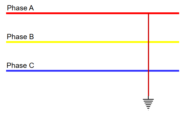
5.1 Description
A single line-to-ground fault occurs when one phase conductor comes into contact with the ground or the neutral conductor. Only one phase is involved in this fault. The other two phases continue to operate normally, at least initially.
This is the most frequently occurring fault type in power systems. Approximately 70-80% of all faults fall into this category. SLG faults commonly occur on overhead transmission and distribution lines due to insulator flashover, tree contact, broken conductors falling to the ground, and animal contact.
5.2 ANSI Codes for SLG Fault Protection
- ANSI 50N / 51N – Ground Overcurrent Relay (instantaneous and time-delayed)
- ANSI 50G / 51G – Ground Fault Relay
- ANSI 67N – Directional Ground Overcurrent Relay
- ANSI 59N – Neutral Overvoltage Relay (used for detecting ground faults in ungrounded or high-impedance grounded systems)
5.3 Characteristics
During an SLG fault, the faulted phase carries a high fault current to ground. The voltage on the faulted phase drops significantly at the fault location. The voltages on the other two unfaulted phases may rise above their normal values. This voltage rise can be as high as 1.732 times (√3) the normal phase voltage in an ungrounded system.
The fault current magnitude in an SLG fault depends heavily on the system grounding method. In a solidly grounded system, the SLG fault current can be very high, sometimes exceeding the three-phase fault current. In a resistance-grounded or impedance-grounded system, the SLG fault current is limited to a lower value.
5.4 Analysis Using Symmetrical Components
For an SLG fault, all three sequence networks (positive, negative, and zero) are connected in series. The fault current is given by:
\(I_{fault} = 3 \times \dfrac{V}{(Z_1 + Z_2 + Z_0 + 3Z_f)}\)
Where:
- \(V\) = Pre-fault voltage
- \(Z_1\) = Positive-sequence impedance
- \(Z_2\) = Negative-sequence impedance
- \(Z_0\) = Zero-sequence impedance
- \(Z_f\) = Fault impedance (zero for a bolted fault)
5.5 Example
On a distribution feeder, a tree branch falls on the Phase A conductor and creates a path to ground. The fault current flows from Phase A through the tree and into the earth, then returns through the grounding system back to the source. Phases B and C are unaffected directly, but their voltages shift due to the unbalanced condition.
6. Line-to-Line Fault (L-L)
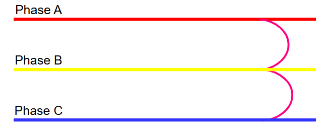
6.1 Description
A line-to-line fault occurs when two phase conductors come into direct contact with each other without involving the ground. This fault type accounts for approximately 15-20% of all faults in power systems.
L-L faults commonly occur due to high winds causing conductors to swing and touch each other, insulation breakdown between phases in cables, and contamination or tracking on insulators. In overhead lines, galloping (wind-induced conductor motion) is a frequent cause of line-to-line faults.
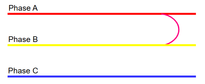
6.2 Characteristics
During a line-to-line fault, the two faulted phases carry equal and opposite fault currents. The third phase carries no fault current (in a pure L-L fault without ground involvement). The fault current magnitude in an L-L fault is approximately 86.6% (√3/2) of the three-phase fault current for the same location.
The voltage between the two faulted phases drops to zero at the fault point (for a bolted fault). The voltage on the unfaulted phase remains relatively unchanged.
6.3 Analysis Using Symmetrical Components
For a line-to-line fault, the positive-sequence and negative-sequence networks are connected in parallel. The zero-sequence network is not involved because there is no ground path. The fault current is:
\(I_{fault} = \sqrt{3} \times \dfrac{V}{(Z_1 + Z_2 + Z_f)}\)
6.4 Example
During a storm with high winds, the Phase B and Phase C conductors on a 132 kV transmission line swing together and make contact. The fault current flows from Phase B to Phase C (and vice versa) through the point of contact. Phase A is not involved. The protective relays detect the overcurrent on phases B and C and trip the circuit breaker accordingly.
7. Double Line-to-Ground Fault (DLG or L-L-G)
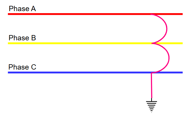
7.1 Description
A double line-to-ground fault occurs when two phase conductors simultaneously come into contact with each other and with the ground. This fault type accounts for approximately 5-10% of all faults. It is more severe than an SLG fault or an L-L fault and can produce fault currents approaching the three-phase fault level.
DLG faults can occur when a tower or pole falls, bringing two conductors to the ground simultaneously. They also occur inside equipment such as transformers and switchgear where insulation failure can involve multiple phases and the grounded enclosure.
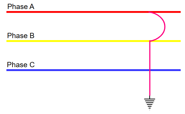
7.2 Characteristics
During a DLG fault, the two faulted phases carry large fault currents that flow both between the phases and to ground. The ground current is the sum of the zero-sequence currents. The voltage on the two faulted phases drops to ground potential at the fault location, and the unfaulted phase voltage may rise above normal.
The fault current magnitude in a DLG fault is higher than both SLG and L-L faults. In some system configurations, particularly in solidly grounded systems with low zero-sequence impedance, the DLG fault current can actually exceed the three-phase fault current.
7.3 Analysis Using Symmetrical Components
For a DLG fault, the positive-sequence network is connected in series with the parallel combination of the negative-sequence and zero-sequence networks. The calculation is more involved than the other fault types. The fault current expressions are:
\(I_{a1} = \dfrac{V}{\left[Z1 + \frac{(Z_2 \times (Z_0 + 3Z_f))}{(Z_2 + Z_0 + 3Z_f)}\right]}\)
The total fault current is then obtained by transforming the sequence components back to phase quantities using the symmetrical components transformation matrix.
7.4 Example
A utility pole carrying a three-phase distribution line is struck by a vehicle. The pole breaks, and two of the three conductors (Phase B and Phase C) fall to the ground. Both conductors make contact with the earth and with each other. The fault current flows through both phases to ground, and the protective devices at the substation detect the overcurrent and ground fault simultaneously, tripping the circuit breaker to isolate the faulted section.
8. Comparison: Symmetrical vs. Asymmetrical Faults
The following table shows the differences between symmetrical and asymmetrical faults across several parameters.
| Parameter | Symmetrical Fault | Asymmetrical Fault |
|---|---|---|
| Definition | A fault that affects all three phases equally and simultaneously | A fault that affects one or two phases and does not involve all three phases equally |
| Phases Involved | All three phases are involved equally | One or two phases are involved |
| System Balance | The system remains balanced | The system becomes unbalanced |
| Types | Three-phase fault (L-L-L) and three-phase-to-ground fault (L-L-L-G) | Single line-to-ground (SLG), line-to-line (L-L), and double line-to-ground (DLG) |
| Frequency of Occurrence | Rare (approximately 2-5% of all faults) | Very common (approximately 95-98% of all faults) |
| Most Common Subtype | Three-phase short circuit | Single line-to-ground fault |
| Fault Current Magnitude | Highest fault current | Produces lower fault currents compared to three-phase faults |
| Severity | Most severe | Less severe |
| Voltage Effect on Faulted Phases | Voltage drops equally on all three phases | Voltage drops only on the faulted phase |
| Sequence Networks Required | Only positive-sequence network is needed | All three sequence networks (positive, negative, and zero) |
9. Symmetrical Components Method
The symmetrical components method is the standard analytical tool for studying asymmetrical faults. Charles Fortescue introduced this method in 1918, and it remains the foundation of modern fault analysis.
9.1 The Three Sequence Components
Any unbalanced set of three-phase phasors can be decomposed into three balanced sets:
Positive-sequence components (V1, I1): Three phasors of equal magnitude, displaced 120 degrees apart, rotating in the normal (ABC) sequence. This component represents the normal operating condition of the power system.
Negative-sequence components (V2, I2): Three phasors of equal magnitude, displaced 120 degrees apart, rotating in the reverse (ACB) sequence. This component appears only during unbalanced conditions.
Zero-sequence components (V0, I0): Three phasors of equal magnitude and equal phase angle (all in phase with each other). This component represents current flowing equally in all three phases and returning through the ground or neutral.
9.2 Sequence Networks
Each sequence component has its own impedance network:
Positive-sequence network: Includes the generator EMF and all positive-sequence impedances. This network looks like the normal system impedance diagram.
Negative-sequence network: Includes only negative-sequence impedances. There is no EMF source in this network because generators do not produce negative-sequence voltages under normal conditions.
Zero-sequence network: Includes zero-sequence impedances and depends heavily on the transformer winding connections and system grounding. Delta-connected transformer windings block zero-sequence current from flowing through them, and this must be reflected in the zero-sequence network.
9.3 Application to Different Fault Types
The way these three sequence networks are interconnected depends on the fault type:
| Fault Type | Network Connection |
|---|---|
| Three-phase (symmetrical) | Positive-sequence only |
| Single line-to-ground | All three in series |
| Line-to-line | Positive and negative in parallel |
| Double line-to-ground | Positive in series with (negative parallel with zero) |
This systematic approach makes it possible to calculate fault currents for any type of fault at any location in the power system accurately.
10. Effects of Symmetrical and Asymmetrical Faults on Power Systems
10.1 Thermal Effects
Fault currents generate heat proportional to I²R (where I is the fault current and R is the resistance of the conductor). This heat can melt conductors, destroy insulation, and cause fires. Three-phase faults, producing the highest fault currents, cause the most severe thermal damage. Protective devices must clear faults within a few cycles to prevent thermal damage.
10.2 Mechanical Effects
The electromagnetic forces between conductors carrying fault currents are proportional to the square of the current. These forces can bend busbars, break insulators, and physically deform switchgear enclosures. Equipment must be designed to withstand these forces for the duration of the fault.
10.3 Voltage Depression
Faults cause voltage drops throughout the power system, not just at the fault location. A three-phase fault causes uniform voltage depression across all phases. Asymmetrical faults cause uneven voltage depression, which can be particularly problematic for sensitive electronic equipment and motor loads.
10.4 Negative-Sequence Effects
Asymmetrical faults produce negative-sequence currents that flow into generators and motors. Negative-sequence currents create a magnetic field rotating in the opposite direction to the rotor, inducing double-frequency currents in the rotor surface. These currents cause rapid heating of the rotor and can damage the machine if not cleared quickly. The ANSI 46 negative-sequence overcurrent relay is specifically designed to protect generators and motors from this condition.
10.5 Zero-Sequence Effects
SLG and DLG faults produce zero-sequence currents that flow through the ground path. These ground currents can cause dangerous step and touch potentials near grounding electrodes. They can also interfere with communication circuits and pipelines running parallel to the power line through electromagnetic induction.
11. System Grounding and Its Influence on Fault Behavior
The method of system grounding has an influence on how asymmetrical faults behave, particularly SLG and DLG faults. The grounding method does not affect symmetrical three-phase faults because no ground path is involved in a three-phase fault.
11.1 Solidly Grounded Systems
In solidly grounded systems, the neutral point is connected directly to ground without any intentional impedance. SLG fault currents are high, often comparable to three-phase fault currents. This arrangement allows easy detection of ground faults using conventional overcurrent relays. Most transmission systems (above 100 kV) and low-voltage systems (below 600 V) use solid grounding.
11.2 Resistance Grounded Systems
In resistance-grounded systems, a resistor is inserted between the neutral and ground. This limits the SLG fault current to a predetermined value, reducing arc damage and step/touch potentials. Medium-voltage industrial systems (2.4 kV to 15 kV) frequently use resistance grounding. The ground fault current is limited to values between 100 A and 2000 A depending on the resistor value chosen.
11.3 Reactance Grounded Systems
Reactance grounding uses an inductor (reactor) between the neutral and ground. This is less common but is used in some specific applications. The ground fault current is limited, but not as effectively as with resistance grounding for limiting transient overvoltages.
11.4 Ungrounded Systems
In ungrounded systems, there is no intentional connection between the neutral and ground. The SLG fault current is very small, consisting only of the system’s distributed capacitive charging current. This allows the system to continue operating with a single ground fault present. However, the voltages on the unfaulted phases rise to line-to-line voltage levels, and a second ground fault on a different phase will result in a phase-to-phase fault through ground. Ungrounded systems also suffer from arcing ground fault overvoltages that can reach 5-6 times normal voltage transiently.
11.5 Resonant Grounded Systems (Petersen Coil)
A Petersen coil is a variable reactor connected between the neutral and ground. It is tuned to match the system’s capacitive current, causing the fault current at the ground fault location to be nearly zero. This allows self-extinction of arcing ground faults. Resonant grounding is widely used in European distribution networks.
12. Fault Analysis in Practice: Steps and Tools
12.1 Manual Calculation Steps
The process of manual fault analysis follows a structured sequence:
- Step 1: Develop the single-line diagram of the power system showing all generators, transformers, lines, and loads with their impedance values.
- Step 2: Convert all impedances to a common per-unit base (the system MVA base and voltage base).
- Step 3: Construct the positive-sequence, negative-sequence, and zero-sequence impedance networks.
- Step 4: Determine the total Thevenin impedance as seen from the fault point for each sequence network.
- Step 5: Interconnect the sequence networks according to the fault type being analyzed.
- Step 6: Calculate the sequence currents and voltages at the fault point.
- Step 7: Transform the sequence quantities back to phase quantities using the symmetrical components transformation.
- Step 8: Calculate the fault current contributions from each source in the system.
12.2 Software Tools
Modern power system analysis uses specialized software for fault calculations. Some widely used tools include:
- ETAP – Popular in industrial and utility applications
- SKM PowerTools – Used for industrial power system design
- ASPEN OneLiner – Focused on transmission system fault analysis
- DIgSILENT PowerFactory – Used globally for transmission and distribution analysis
- PSCAD – Used for electromagnetic transient simulations
- EasyPower – User-friendly tool for industrial power studies
These software tools can perform fault calculations at every bus in the system simultaneously and generate reports showing fault current magnitudes, X/R ratios, and individual source contributions at each fault location.
13. Standards and References
Several industry standards govern fault analysis and equipment ratings:
- IEEE Std C37.010 – Application Guide for AC High-Voltage Circuit Breakers Based on Symmetrical Current Rating
- IEEE Std 551 (Violet Book) – Calculating Short-Circuit Currents in Industrial and Commercial Power Systems
- IEEE Std 141 (Red Book) – Electric Power Distribution for Industrial Plants
- IEEE Std 242 (Buff Book) – Protection and Coordination of Industrial and Commercial Power Systems
- IEC 60909 – Short-Circuit Currents in Three-Phase AC Systems
- IEC 62271 – High-Voltage Switchgear and Controlgear
- ANSI C37 Series – Standards for circuit breakers, switchgear, and relays
These standards provide detailed procedures for calculating fault currents, selecting equipment ratings, and coordinating protective devices properly.
14. Conclusion
Symmetrical and asymmetrical faults are the two fundamental categories of faults in three-phase power systems. Symmetrical faults affect all three phases equally and produce the highest fault currents in most systems, making them the basis for equipment interrupting ratings. Asymmetrical faults are far more common and include single line-to-ground, line-to-line, and double line-to-ground faults. Each fault type has distinct characteristics, and each requires specific analytical techniques for accurate calculation.
The method of symmetrical components provides the mathematical framework for analyzing all fault types within a unified approach. Protective relays with various ANSI designations are deployed to detect and respond to each fault type appropriately. System grounding plays a major role in determining the behavior and magnitude of ground faults.
15. Frequently Asked Questions (FAQs)
A symmetrical fault affects all three phases equally and the system remains balanced during the fault. An asymmetrical fault affects one or two phases, causing the system to become unbalanced. Three-phase short circuits are symmetrical faults. SLG, L-L, and DLG faults are asymmetrical faults.
The single line-to-ground (SLG) fault is the most common, accounting for approximately 70-80% of all faults. It is an asymmetrical fault type.
In most power systems, the three-phase symmetrical fault produces the highest fault current.
Circuit breakers are rated based on the symmetrical (AC) component of the fault current because this is the sustained component that determines the interrupting duty. The DC offset (which makes the total current asymmetrical) is accounted for separately through asymmetry factors or peak current ratings.
It is a mathematical technique developed by Charles Fortescue to analyze unbalanced three-phase systems. It decomposes any unbalanced set of three-phase quantities into three balanced sets: positive-sequence, negative-sequence, and zero-sequence components.
Zero-sequence impedance determines the magnitude of ground fault currents. It is needed for analyzing SLG and DLG faults.
Yes. Asymmetrical faults produce negative-sequence currents that flow into generators. These currents induce double-frequency currents in the rotor, causing rapid overheating.
A bolted fault is a short circuit with zero fault impedance. It represents the worst-case scenario and produces the maximum possible fault current at a given location.