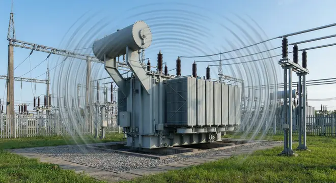
If you have ever stood near a power transformer or a distribution substation, you have probably heard a low-frequency humming or buzzing sound. This sound is so common that many engineers treat it as normal background noise. However, when the humming becomes loud, it signals a problem that deserves immediate attention. Loud transformer humming can indicate internal faults, core saturation, harmonic distortion, loose components, or degraded mounting systems. Ignoring this issue can lead to accelerated aging, insulation breakdown, and even failure.
Transformer noise is not just a technical concern. It also creates environmental disturbance, especially in residential neighborhoods, commercial buildings, and hospital zones. Regulatory bodies in countries like the United States, Canada, the United Kingdom, Australia, and Germany have strict noise emission standards. Violating these standards can result in hefty fines and forced shutdowns.
In this technical guide, we will discuss everything you need to know about loud transformer humming, including its root causes, the physics behind it, measurement techniques, transformer noise reduction strategies, harmonic effects, vibration isolation methods, acoustic treatments, and diagnostic procedures. Practical examples are included throughout to help you apply these concepts in real-world scenarios confidently.
1. What Is Transformer Humming?
Transformer humming is the audible sound produced by a transformer during normal operation. Every transformer produces some level of noise. The primary source of this noise is a phenomenon called magnetostriction. Magnetostriction is the mechanical deformation of the transformer’s iron core when it is subjected to a magnetic field. As the alternating current flows through the windings, the magnetic flux in the core changes direction 100 or 120 times per second (depending on whether the system frequency is 50 Hz or 60 Hz). This rapid expansion and contraction of the core laminations produces vibrations that radiate as audible sound.
Under ideal conditions, this hum is relatively quiet and consistent. It is often described as a steady, low-pitched tone at twice the supply frequency. For a 60 Hz system, the fundamental hum frequency is 120 Hz. For a 50 Hz system, it is 100 Hz. Harmonics of these frequencies (240 Hz, 360 Hz, 480 Hz, and so on) may also be present.
The hum becomes a problem when its intensity increases beyond acceptable limits.
2. The Physics Behind Magnetostriction
To understand loud transformer humming properly, you need to understand magnetostriction at a deeper level. Magnetostriction occurs because ferromagnetic materials like silicon steel change their physical dimensions in response to magnetization. The core laminations expand slightly when magnetized and return to their original dimensions when the magnetic field passes through zero.
This dimensional change is extremely small, measured in micrometers. However, because it happens at very high frequency and involves a large mass of iron, the cumulative effect produces audible vibrations.
The intensity of magnetostriction depends on several factors:
- Flux density in the core: Higher flux density causes greater dimensional change.
- Core material grade: Grain-oriented silicon steel (GOES) has lower magnetostriction than non-oriented grades.
- Core construction quality: Poorly assembled cores with air gaps or uneven clamping vibrate more loudly.
- Operating voltage: Overvoltage conditions push the core toward saturation, increasing magnetostriction sharply.
For example, a transformer designed to operate at 1.7 Tesla flux density will produce more noise than one designed for 1.5 Tesla, all else being equal. Manufacturers balance noise performance against material cost during the design phase carefully.
3. Common Causes of Loud Transformer Humming
Several conditions can cause a transformer to hum louder than expected. Let us examine each one in detail below.
3.1 Core Saturation
Core saturation is one of the most frequent causes of abnormally loud humming. A transformer core is designed to operate within a specific range of magnetic flux density. If the applied voltage exceeds the design value, the core enters saturation. In this state, the relationship between flux and magnetizing current becomes nonlinear. The core draws excessive magnetizing current, and the magnetostriction effect intensifies.
Overvoltage conditions can result from tap changer misadjustment, voltage regulation issues, or upstream switching events.
Example: A 13.8 kV / 480 V distribution transformer is designed for a maximum flux density of 1.65 Tesla. If the primary voltage rises to 14.5 kV due to a voltage regulation error, the flux density may exceed 1.75 Tesla. The transformer will produce a much louder hum and may also generate excessive heat.
3.2 Harmonic Distortion
Modern electrical systems are loaded with nonlinear devices such as variable frequency drives (VFDs), LED lighting, rectifiers, UPS systems, and switch-mode power supplies. These devices inject harmonic currents into the network. Harmonics create additional flux components in the transformer core at frequencies that are multiples of the fundamental.
Each harmonic component contributes its own magnetostriction effect. The 3rd, 5th, 7th, and 11th harmonics are particularly troublesome. The combined effect raises the overall noise level. Harmonic mitigation techniques become necessary in such environments to keep the transformer quiet and operating within thermal limits.
Example: A 1000 kVA dry-type transformer feeding a data center experiences a Total Harmonic Distortion (THD) of 28% on the current waveform. The transformer hums louder than its nameplate sound level rating because the core is experiencing magnetostriction at 240 Hz, 360 Hz, 480 Hz, and higher even multiples of the supply frequency simultaneously.
3.3 Loose Core Laminations and Clamping
Over time, the clamping bolts and structural supports that hold the core laminations together can loosen due to thermal cycling, vibration fatigue, or mechanical shock. When laminations become loose, they vibrate independently instead of as a unified mass. This produces a buzzing sound that is distinctly different from the normal magnetostrictive hum. It sounds more erratic and harsh.
Loose laminations also lead to localized heating at the contact points, which degrades the insulation between laminations progressively.
3.4 Loose Windings and Internal Components
Similar to core loosening, the windings themselves can shift over time. High fault currents during short circuits exert enormous electromagnetic forces on the winding conductors. After repeated fault events, the winding geometry may change slightly. Loose windings vibrate at power frequency and its harmonics, adding to the overall noise output.
Internal components like shielding, lead connections, and tank bracing can also become loose contributors.
3.5 DC Offset (Geomagnetically Induced Currents)
In regions susceptible to geomagnetic storms such as Canada, Scandinavia, and parts of the United States geomagnetically induced currents (GICs) can flow through the transformer windings. These are quasi-DC currents that bias the core magnetization asymmetrically. The resulting half-cycle saturation produces very loud humming and buzzing. The sound is irregular and often accompanied by increased reactive power consumption.
Example: During the March 1989 geomagnetic storm, transformers across Quebec, Canada, experienced extreme humming and buzzing before the Hydro-Québec grid collapsed entirely.
3.6 Fan and Pump Noise
Oil-forced air-forced (OFAF) and oil-forced water-forced (OFWF) cooling systems use fans and pumps that generate mechanical noise. If the bearings wear out, the blades become unbalanced, or the motor mounts deteriorate, the cooling system contributes additional noise. This noise often overlaps with the magnetostrictive hum and can make diagnosis difficult initially.
3.7 Stray Flux Effects
Stray magnetic flux can induce eddy currents in the transformer tank, structural steelwork, and mounting hardware. These eddy currents cause local heating and vibration. The vibration radiates as audible noise from the tank walls. Poorly designed magnetic shielding or saturated flux shunts worsen this effect considerably.
4. How Loud Is Too Loud? ANSI and NEMA Standards
The acceptable noise level for a transformer depends on its rating, type, and installation environment. Several industry standards govern transformer sound levels directly.
4.1 ANSI/NEMA Standards
NEMA TR 1 (Transformers, Regulators, and Reactors) specifies maximum sound levels for liquid-filled transformers based on their kVA rating. The sound levels are measured in decibels (dB) on the A-weighted scale (dBA).
| Transformer Rating (kVA) | Maximum Sound Level (dBA) |
|---|---|
| 0 – 300 | 55 |
| 301 – 500 | 57 |
| 501 – 700 | 59 |
| 701 – 1,000 | 60 |
| 1,001 – 1,500 | 62 |
| 1,501 – 2,000 | 64 |
| 2,001 – 3,000 | 65 |
| 3,001 – 5,000 | 67 |
| 5,001 – 7,500 | 68 |
| 7,501 – 10,000 | 70 |
4.2 IEC Standards
IEC 60076-10 deals specifically with the determination of sound levels for power transformers and reactors. It provides detailed measurement procedures, including near-field and far-field methods.
IEC 60076-10-1 is an application guide that helps engineers interpret and apply the measurement results from IEC 60076-10 in practice.
4.3 Local Noise Ordinances
Beyond transformer-specific standards, local noise ordinances apply in many jurisdictions strictly. For instance, in urban areas of the United States, nighttime noise limits at the property boundary may be as low as 40–45 dBA. A transformer that meets NEMA TR 1 at 67 dBA at one meter may still violate local ordinances if the substation is close to residential properties.
5. How to Measure Transformer Noise
Measuring transformer noise accurately requires following standardized procedures. Here is a summary of the measurement method outlined in ANSI/IEEE C57.12.90 and IEC 60076-10.
5.1 Equipment Required
- A precision sound level meter with A-weighting filter (Class 1 or Class 2 per ANSI S1.4 / IEC 61672).
- A calibrator for the sound level meter.
- A tripod or fixed mounting system for consistent positioning.
- An anemometer (wind can affect outdoor readings).
5.2 Measurement Procedure
- Background noise measurement: Measure the ambient noise level with the transformer de-energized. The background noise should be at least 5 dB below the expected transformer noise. If it is between 3 and 5 dB below, apply the correction factor per the applicable standard.
- Measurement distance: Place the microphone at a distance of 0.3 meters (approximately 1 foot) from the transformer tank surface for the near-field method. For far-field measurements, use the distance specified in the purchase specification or local ordinance.
- Measurement points: Take readings at multiple points around the transformer at the mid-height of the tank. Space the measurement points evenly — usually every 1 meter along the perimeter.
- Operating condition: The transformer should be energized at rated voltage and frequency with no load applied. Load noise testing is performed separately if required.
- Data recording: Record individual readings and compute the average sound level.
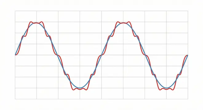
6. Frequency Spectrum Analysis of Transformer Noise
A simple dBA reading tells you the overall noise level, but it does not reveal the frequency content. Frequency spectrum analysis is extremely valuable for diagnosing the cause of loud transformer humming accurately.
Use a sound level meter with octave band or one-third octave band analysis capability. The dominant frequencies will tell you a lot:
- 120 Hz (or 100 Hz for 50 Hz systems): This is the fundamental magnetostrictive frequency. If this dominates, the core is the primary noise source.
- 240 Hz, 360 Hz, 480 Hz: These are harmonics of the fundamental. If higher harmonics are strong, suspect harmonic distortion on the supply or load side.
- Broadband noise: A wide spread of frequencies suggests mechanical looseness, fan noise, or oil turbulence.
- Pure tones: A single dominant frequency can be particularly annoying to human ears, even at moderate levels. This is because the human auditory system is more sensitive to tonal noise than broadband noise.
Power quality analysis should accompany acoustic testing whenever harmonic distortion is suspected. Use a power quality analyzer to measure voltage and current THD simultaneously with the noise measurements.
7. Effects of Loud Transformer Humming
Loud humming is more than just an annoyance. It has technical, operational, and social consequences that engineers must address seriously.
7.1 Technical Effects
- Accelerated insulation aging: The vibrations associated with loud humming generate heat at contact points and joints. This localized heating accelerates the thermal degradation of paper and oil insulation.
- Loosening of connections: Persistent vibration can loosen bolted connections, bushing terminals, and tap changer contacts over time.
- Structural fatigue: The transformer tank and mounting frame experience fatigue loading from continuous vibration. Cracks can develop in welds and at stress concentration points eventually.
7.2 Operational Effects
- Increased maintenance costs: Loud transformers require more frequent inspections, tightening, and monitoring.
- Reduced transformer lifespan: The combined effects of heat, vibration, and insulation degradation shorten the useful life of the equipment measurably.
- Unplanned outages: In severe cases, the root cause of loud humming (such as a loose core or winding) can lead to an internal fault and forced outage.
7.3 Social and Regulatory Effects
- Community complaints: Residential areas near substations are particularly sensitive to noise. Persistent low-frequency hum can cause sleep disturbance, stress, and reduced quality of life.
- Regulatory penalties: Violating local noise ordinances can result in fines, legal action, and mandatory remediation.
8. Transformer Noise Reduction Strategies
There are many approaches to reducing transformer humming noise. The best strategy depends on the root cause, the transformer type, the installation environment, and the budget available. Let us explore the options below.
8.1 Design-Level Noise Reduction
The most effective way to achieve a quiet transformer is to design it for low noise from the beginning. Manufacturers can reduce noise by:
- Using lower flux density: Designing the core to operate at a lower flux density (e.g., 1.5 T instead of 1.7 T) reduces magnetostriction. This requires more core material, which increases cost and weight.
- Using high-grade core steel: Grain-oriented silicon steel with laser-scribed domains (such as Hi-B or domain-refined grades) exhibits lower magnetostriction.
- Step-lap core joints: Modern step-lap joint designs reduce flux concentration at the core joints, which lowers noise compared to traditional mitred joints.
- Optimized core clamping: Proper clamping pressure distributed evenly across the core prevents lamination buzzing.
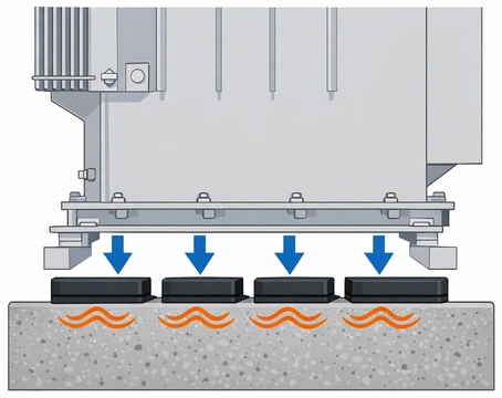
8.2 Vibration Isolation Pads
Vibration isolation pads are one of the most practical and cost-effective noise reduction methods for existing transformers. These pads are placed between the transformer base and its foundation. They prevent structural vibrations from transmitting into the floor or mounting platform.
Common pad materials include:
- Neoprene rubber
- Cork-rubber composites
- Spring isolators
- Fiberglass pads
The pads should be selected based on the transformer weight, the dominant vibration frequency, and the required isolation efficiency. A properly designed vibration isolation system can reduce structure-borne noise by 10–20 dB.
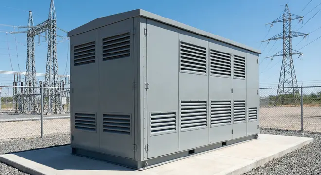
8.3 Acoustic Enclosures for Equipment
When airborne noise is the main concern, acoustic enclosures for equipment offer a highly effective solution. These enclosures surround the transformer with sound-absorbing panels made from materials like mineral wool, perforated metal, and mass-loaded vinyl.
Design considerations for acoustic enclosures include:
- Ventilation: The enclosure must allow adequate airflow for cooling. Acoustic louvers or silenced ventilation openings are used.
- Access: Panels should be removable or hinged for maintenance access.
- Fire resistance: The enclosure materials must meet fire safety requirements, especially for indoor installations.
- Structural support: The enclosure must be self-supporting and not rigidly attached to the transformer to avoid becoming a secondary noise source.
8.4 Active Noise Cancellation
Active noise cancellation (ANC) systems use microphones to detect the transformer hum and loudspeakers to emit an anti-phase sound wave that cancels the noise. This technology works best for tonal noise at known frequencies (such as 120 Hz and its harmonics).
ANC systems have been successfully deployed on large power transformers in urban substations in countries like Japan, Germany, and Australia. However, they are complex, expensive, and require ongoing maintenance and calibration.
8.5 Harmonic Filtering
If harmonic distortion is the cause of increased noise, installing harmonic filters on the transformer’s load side can reduce the harmonic currents flowing through the windings. Passive harmonic filters tuned to the dominant harmonic frequencies (5th, 7th, 11th) are commonly used. Active harmonic filters offer broader harmonic mitigation and can adapt to changing load conditions dynamically.
Reducing the current THD from 30% to below 8% can lower the transformer noise level by several decibels.
8.6 Voltage Regulation
If overvoltage is causing core saturation and loud humming, correcting the voltage regulation solves the problem directly. Check the tap changer position and adjust it to bring the secondary voltage within the rated range. For systems with chronic voltage regulation issues, install automatic voltage regulators (AVRs) or on-load tap changers (OLTCs).
8.7 Core and Winding Retightening
For transformers with loose core laminations or windings, a retightening procedure can restore the original noise level. This requires de-energizing and opening the transformer, which involves a planned outage. For oil-filled units, this work must be performed by qualified personnel following strict safety protocols. Electrical transformer repair of this nature should be done by experienced service providers with proper equipment.
8.8 Tank Damping
Applying damping materials to the outside of the transformer tank can reduce the radiation of noise from the tank walls. Viscoelastic damping sheets or constrained-layer damping treatments absorb vibration energy and convert it to heat (in negligible amounts). Tank damping can reduce noise by 3–8 dB for specific frequency ranges.
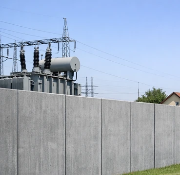
8.9 Barrier Walls
For outdoor substations, building a masonry or concrete barrier wall between the transformer and the noise-sensitive area provides a simple and durable solution. A 3-meter-high concrete wall can reduce noise by 10–15 dB at the receiver location, depending on the geometry and distance.
9. Summary Table: Causes and Solutions
| Cause | Primary Symptom | Recommended Solution |
|---|---|---|
| Core saturation (overvoltage) | Loud 120 Hz hum | Adjust tap changer, regulate voltage |
| Harmonic distortion | Multi-frequency buzzing | Install harmonic filters, harmonic mitigation |
| Loose core laminations | Erratic buzzing | Retighten core clamps, electrical transformer repair |
| Loose windings | Vibration under load | Internal inspection and repair |
| DC offset / GIC | Irregular loud hum | Install DC blocking devices |
| Fan / pump noise | Broadband noise | Replace bearings, balance blades |
| Structural resonance | Amplified hum at specific frequency | Vibration isolation pads, damping |
| Tank radiation | Noise from tank walls | Tank damping, acoustic enclosures for equipment |
10. Conclusion
Loud transformer humming is more than just a nuisance. It is an indicator of electrical, mechanical, or environmental conditions that need attention. The root cause may be as simple as a voltage tap setting error or as complex as harmonic-induced multi-frequency core excitation. Engineers working with power systems must know how to measure, diagnose, and resolve transformer noise issues following established ANSI, IEEE, and IEC standards.
Addressing loud transformer humming protects the equipment, extends its service life, maintains regulatory compliance, and preserves good relationships with neighboring communities simultaneously.
11. Frequently Asked Questions
A transformer hums at twice the power system frequency. For a 60 Hz system, the fundamental hum is 120 Hz. For a 50 Hz system, it is 100 Hz. Harmonics at 240 Hz, 360 Hz, 480 Hz, and higher may also be present.
The humming itself is not dangerous to humans. However, a sudden increase in noise level may indicate internal problems such as core saturation, loose laminations, or winding displacement.
You can install vibration isolation pads under the transformer to reduce structure-borne noise. For airborne noise, consider acoustic enclosures for equipment or sound-absorbing wall treatments.
Yes. Harmonic currents create additional magnetic flux components in the core at frequencies above the fundamental. Each harmonic contributes its own magnetostriction, increasing the overall noise level.
Magnetostriction is the physical expansion and contraction of iron core material when it is magnetized. In a transformer, the alternating magnetic field causes the core to vibrate at twice the supply frequency. This vibration is the primary source of the humming sound.
The transformer may not actually be louder. Ambient background noise drops at night, making the transformer hum more perceptible. However, if the voltage tends to rise during low-load nighttime periods, the core may enter saturation, producing genuinely louder noise.
No. Every energized transformer produces some magnetostrictive noise. However, it can be reduced to very low levels through proper design, vibration isolation pads, acoustic enclosures, and voltage regulation.
Noise measurements should be taken during commissioning, after any major maintenance or repair, and periodically (annually or biannually) as part of a condition monitoring program.
Yes. Load current generates additional electromagnetic forces on the windings and creates additional flux leakage that can cause vibration.