Every transformer that enters service in a power system must undergo specific tests to verify its performance characteristics. Among these tests, the short circuit test holds a special place because it allows engineers to determine copper losses and impedance parameters without connecting any actual load to the transformer. This saves time, reduces cost, and eliminates the need for expensive load banks during testing.
The short circuit test works on a straightforward principle. You apply a small fraction of the rated voltage to one winding and short circuit the other winding completely. The voltage is raised gradually until full-load current flows through the windings. At that point, you record voltage, current, and power readings. These three readings are enough to calculate the equivalent resistance, reactance, impedance, and full-load copper losses of the transformer.
In this technical guide, we will discuss everything you need to know about the short circuit test of a transformer, including its working principle, circuit arrangement, step-by-step procedure, mathematical calculations, practical examples, and comparison with the open circuit test. Practical examples are included throughout to help you apply these concepts in real-world scenarios confidently.
1. What is the Short Circuit Test of a Transformer?
The short circuit test is a method used to measure the copper losses and series impedance parameters of a transformer. During this test, the secondary winding terminals are connected together using a thick copper conductor. A low voltage is then applied to the primary winding through a variable voltage source.
The applied voltage starts from zero and increases slowly. As the voltage rises, current begins to flow through both windings. The voltage is increased until the ammeter shows the rated full-load current of the transformer. At this point, three instrument readings are taken — voltage, current, and power.
The voltage required to push full-load current through the short-circuited transformer is very small. It falls in the range of 5% to 10% of the rated primary voltage. Because the voltage is so low, the magnetic flux in the core remains at a very low level. Core losses depend on flux density, and at such reduced flux levels, iron losses become negligible. The wattmeter reading therefore represents almost entirely the copper losses occurring in both windings.
This test gives you the full-load copper loss, equivalent resistance, equivalent reactance, equivalent impedance, and percentage impedance of the transformer all from just three meter readings.
2. Why is the Short Circuit Test Performed on the High Voltage Side?
The short circuit test is performed from the high voltage (HV) side of the transformer in most practical situations. The low voltage (LV) terminals are shorted during the test. This arrangement is preferred for practical reasons rather than any theoretical requirement. Theoretically, the test can be performed from either side, and the results can be referred to either winding through the turns ratio. However, the HV side offers clear advantages in practice.
The high voltage winding carries a lower current compared to the low voltage winding for the same power rating. A transformer rated at 10 kVA with a primary voltage of 2000 V has a primary current of only 5 A. The same transformer with a secondary voltage of 200 V has a secondary current of 50 A. Measuring 5 A is far easier and more economical than measuring 50 A.
The instruments required on the HV side have lower current ratings, which makes them smaller, cheaper, and more readily available. Current transformers and ammeter shunts needed for high-current measurement add cost and complexity to the test setup.
Power consumption during the test also drops when you work from the HV side. The reduced current requirement means less energy is wasted in the test circuit. This makes the testing process more efficient from an energy standpoint.
3. Circuit Arrangement for the Short Circuit Test
The test setup requires three measuring instruments on the primary (HV) side and a shorting conductor on the secondary (LV) side.
On the HV side, connect the following instruments:
- Wattmeter — to measure the real power input (which equals copper losses)
- Ammeter — connected in series to monitor the current flowing through the primary winding
- Voltmeter — connected across the primary terminals to measure the applied voltage
On the LV side, connect a thick copper bar or conductor across the secondary terminals. This conductor must have adequate cross-sectional area to handle the full-load secondary current safely.
A variable voltage source supplies the controlled voltage to the primary winding. An autotransformer (variac) serves this purpose well because it allows smooth voltage adjustment from zero to the desired level. The variac connects to the main power supply on its input side and feeds the transformer under test on its output side.
All instrument connections must be secure and tight. Loose connections introduce additional resistance that can distort the test results. The current-carrying leads should have sufficient gauge to handle the test current without producing measurable voltage drops.

4. Safety Precautions
Before performing the short circuit test, you must observe several safety measures. Placing these precautions before the procedure helps you prepare properly and avoid hazards during the test.
Always verify that the transformer is properly grounded before beginning the test. The test area should be clearly marked and restricted to authorized personnel only.
Use test leads with adequate cross-sectional area to handle the full-load current without overheating. Poor connections can create additional resistance that affects measurement accuracy and poses a fire hazard.
Never attempt to change connections with voltage applied to the circuit. Always reduce the variac to zero and switch off the power supply before making any modifications.
Monitor the ammeter continuously during voltage increase to avoid exceeding rated current. Operating beyond rated current, even briefly, can overheat the windings and damage the transformer.
Wear appropriate personal protective equipment including insulated gloves and safety glasses. Even though the voltage is low during this test, the high currents involved present their own hazards.
According to ANSI/IEEE C57.12.90 (IEEE Standard Test Code for Liquid-Immersed Distribution, Power, and Regulating Transformers), short circuit tests should be performed following established procedures to maintain both safety and measurement accuracy.
5. Short Circuit Test Procedure: Step by Step
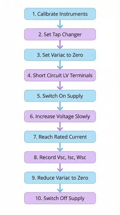
Follow these steps to perform the short circuit test correctly and safely.
- Step 1: Verify that all instruments are calibrated and functioning properly. Check the ammeter, voltmeter, and wattmeter for correct zero readings before starting.
- Step 2: Set the transformer tap changer to its rated tap position. The winding under test should be at its nominal turns ratio.
- Step 3: Set the variac to its minimum position so that the output voltage is zero.
- Step 4: Short circuit the LV terminals using a thick copper conductor. Make sure the connections are firm and the contact resistance is minimal.
- Step 5: Switch on the power supply to the variac.
- Step 6: Increase the variac output slowly. Watch the ammeter reading carefully as the voltage rises.
- Step 7: Continue increasing the voltage until the ammeter reads the rated full-load current of the transformer.
- Step 8: Record all three meter readings immediately — the voltmeter reading \((V_{sc})\), the ammeter reading \((I_{sc})\), and the wattmeter reading \((W_{sc})\). Take the readings quickly to avoid temperature rise in the windings.
- Step 9: Reduce the variac output back to zero.
- Step 10: Switch off the power supply.
The entire test takes only a few minutes. The transformer does not heat up noticeably because the applied voltage is very low and the test duration is short.

6. What Do the Measurements Tell Us?
Each of the three readings obtained during the short circuit test reveals something specific about the transformer. The following section explains the meaning behind each instrument reading before we move into the mathematical derivations.
6.1 Voltmeter Reading \((V_{sc})\)
The voltmeter shows the voltage needed to overcome the internal impedance of the transformer and force full-load current through the windings. This voltage is a small fraction of the rated voltage. When expressed as a percentage of the rated voltage, it gives the percentage impedance of the transformer. This parameter plays a major role in fault current calculations and protective relay coordination.
6.2 Wattmeter Reading \((W_{sc})\)
The wattmeter displays the real power consumed during the test. Since the applied voltage is only 5% to 10% of the rated voltage, the core flux is proportionally reduced. Iron losses drop to negligible values at such low flux levels. The power reading therefore shows only the full-load copper losses in both the primary and secondary windings. This value is used directly in efficiency calculations.
6.3 Ammeter Reading \((I_{sc})\)
The ammeter confirms that the rated full-load current is flowing through the transformer. This verification is necessary to make sure that the copper losses measured correspond to actual full-load operating conditions. The test results become directly applicable to real scenarios only when the current matches the rated value.
The next section shows how to use these three readings mathematically to extract all equivalent circuit parameters.
7. Mathematical Calculations from Short Circuit Test
The three recorded readings \(V_{sc}\), \(I_{sc}\), and \(W_{sc}\) allow you to calculate all the series parameters of the transformer equivalent circuit. All values calculated here are referred to the primary side.
7.1 Equivalent Resistance Referred to Primary \((R_{01})\)
The equivalent resistance accounts for the combined resistive losses in both windings. It is calculated using the power equation:
\(R_{01}=\frac{W_{sc}}{I^2_{sc}}\)
This resistance is the combined effect of primary and secondary winding resistances as seen from the primary side. The wattmeter reading equals I²R losses, so dividing by the square of the current gives the resistance directly.
7.2 Equivalent Impedance Referred to Primary \((Z_{01})\)
The equivalent impedance is the total opposition to current flow offered by the transformer windings. It is found from Ohm’s law:
\(Z_{01}=\frac{V_{sc}}{I_{sc}}\)
The applied voltage drives the current through the total impedance, so their ratio gives the impedance value.
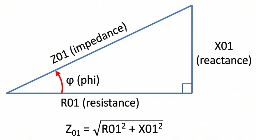
7.3 Equivalent Reactance Referred to Primary \((X_{01})\)
The equivalent reactance is the inductive component of the winding impedance. It is calculated using the impedance triangle relationship:
\(X_{01}=\sqrt{Z^2_{01}-{R^2_{01}}}\)
Since impedance has both resistive and reactive components at right angles, this formula extracts the reactive part.
7.4 Percentage Impedance (%Z)
The percentage impedance tells you what fraction of the rated voltage is needed to circulate full-load current through the transformer. It is calculated as:
\(\%Z=\frac{V_{sc}}{V_{rated}}\times 100\)
This parameter is used extensively in fault level calculations and protection system design. Per ANSI/IEEE C57.12.00, percentage impedance is a nameplate-rated quantity and must fall within specified tolerances.
7.5 Power Factor During Short Circuit Test \((cos \phi)\)
The short circuit power factor indicates the ratio of resistive to total impedance. It is calculated from:
\(cos \phi=\frac{W_{sc}}{V_{sc}\times I_{sc}}\)
This value is always less than unity because the transformer windings have both resistance and reactance.
8. Short Circuit Test Voltage vs Current Graph
The relationship between voltage and current during the short circuit test is linear. As you increase the applied voltage from zero, the current rises proportionally according to Ohm’s law \((V=I\times Z)\). The graph below demonstrates this relationship interactively.
📈 Voltage vs Current Graph
Short Circuit Test Interactive Visualization
9. Practical Example
Consider a transformer where the short circuit test give the following readings:
- Applied voltage \(=15 V\)
- Short circuit current \(=10 A\),
- Wattmeter reading \(=120 W\).
If the transformer's rated primary voltage is \(240 V\), we can calculate all parameters.
The equivalent resistance works out to \(1.20 Ω\), found by dividing \(120 W\) by the square of \(10 A\). The equivalent impedance equals \(1.50 Ω\), obtained by dividing \(15 V\) by \(10 A\). The equivalent reactance then calculates to \(0.90 Ω\) using the impedance triangle relationship. The percentage impedance comes to \(6.25\%\), which is the ratio of \(15 V\) to \(240 V\) multiplied by \(100\). Finally, the power factor during short circuit is \(0.800\), calculated from the ratio of real power to apparent power.
These values provide complete information about the transformer's series impedance characteristics and full-load copper losses. They allow accurate prediction of voltage regulation and efficiency at any load condition.
9.1 Problem 1: During a short circuit test on a single-phase transformer, the following readings were obtained:
- Short circuit voltage, \(V_{sc}\) = 12.5 V
- Short circuit current, \(I_{sc}\) = 8.0 A
- Wattmeter reading, \(W_{sc}\) = 85 W
- Rated primary voltage, \(V_{rated}\) = 230 V
Calculate:
- (a) Equivalent resistance referred to primary \((R_{01})\)
- (b) Equivalent impedance referred to primary \((Z_{01})\)
- (c) Equivalent reactance referred to primary \((X_{01})\)
- (d) Percentage impedance \((\%Z)\)
- (e) Power factor during short circuit test \((\cos\phi)\)
Solution:
(a) Equivalent Resistance:
\(R_{01} = \frac{W_{sc}}{I_{sc}^2} = \frac{85}{8.0^2} = \frac{85}{64}\)
\(R_{01} = 1.3281 \Omega\)
(b) Equivalent Impedance:
\(Z_{01} = \frac{V_{sc}}{I_{sc}} = \frac{12.5}{8.0}\)
\(Z_{01} = 1.5625 \Omega\)
(c) Equivalent Reactance:
\(X_{01} = \sqrt{Z_{01}^2 - R_{01}^2} = \sqrt{(1.5625)^2 - (1.3281)^2}\)
\(X_{01} = \sqrt{2.4414 - 1.7639} = \sqrt{0.6775}\)
\(X_{01} = 0.8231\) Ω
(d) Percentage Impedance:
\(\%Z = \frac{V_{sc}}{V_{rated}} \times 100 = \frac{12.5}{230} \times 100\)
\(\%Z = 5.43\%\)
(e) Power Factor:
\(\cos\phi = \frac{W_{sc}}{V_{sc} \times I_{sc}} = \frac{85}{12.5 \times 8.0} = \frac{85}{100}\)
\(\cos\phi = 0.85\)
9.2 Problem 2: A short circuit test on a transformer gave the following data:
- \(V_{sc} = 18 V\)
- \(I_{sc} = 12 A\)
- \(W_{sc} = 150 W\)
- \(V_{rated} = 400 V\)
Determine the copper losses when the transformer operates at:
- (a) Half load (50%)
- (b) Three-quarter load (75%)
Solution:
The full-load copper loss from the test is \(W_{sc}\) = 150 W
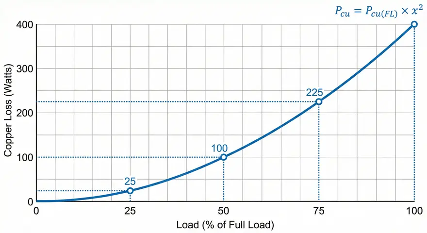
Copper loss varies with the square of the load current:
\(P_{cu(x)} = P_{cu(FL)} \times (\frac{x}{100})^2\)
(a) Copper loss at half load (50%):
\(P_{cu(0.5)} = 150 \times (0.5)^2 = 150 \times 0.25\)
\(P_{cu(0.5)} = 37.50 W\)
(b) Copper loss at three-quarter load (75%):
\(P_{cu(0.75)} = 150 \times (0.75)^2 = 150 \times 0.5625\)
\(P_{cu(0.75)} = 84.38\) W
9.3 Problem 3: In a short circuit test on a transformer, the following observations were made:
- \(V_{sc} = 20 V\)
- \(I_{sc} = 15 A\)
- \(W_{sc} = 200 W\)
The percentage impedance of the transformer is 5%. Calculate:
- (a) Rated primary voltage \((V_{rated})\)
- (b) Equivalent resistance \((R_{01})\)
- (c) Equivalent impedance \((Z_{01})\)
- (d) Equivalent reactance \((X_{01})\)
Solution:
(a) Rated Primary Voltage:
From percentage impedance formula:
\(\%Z = \frac{V_{sc}}{V_{rated}} \times 100\)
\(V_{rated} = \frac{V_{sc} \times 100}{\%Z} = \frac{20 \times 100}{5}\)
\(V_{rated} = 400V\)
(b) Equivalent Resistance:
\(R_{01} = \frac{W_{sc}}{I_{sc}^2} = \frac{200}{15^2} = \frac{200}{225}\)
\(R_{01} = 0.8889\Omega\)
(c) Equivalent Impedance:
\(Z_{01} = \frac{V_{sc}}{I_{sc}} = \frac{20}{15}\)
\(Z_{01} = 1.33Omega\)
(d) Equivalent Reactance:
\(X_{01} = \sqrt{Z_{01}^2 - R_{01}^2} = \sqrt{(1.33)^2 - (0.8889)^2}\)
\(X_{01} = 0.9938\Omega\)
9.4 Problem 4: A transformer has the following equivalent circuit parameters referred to primary:
- \(R_{01}\) = 1.2 \Omega\)
- \(X_{01} = 0.9 \Omega\)
The transformer has a rated current of 10 A and rated primary voltage of 240 V.
Determine the readings that would be obtained during a short circuit test:
- (a) Equivalent impedance \((Z_{01})\)
- (b) Short circuit voltage \((V_{sc})\)
- (c) Wattmeter reading \((W_{sc})\)
- (d) Percentage impedance \((\%Z)\)
Solution:
(a) Equivalent Impedance:
\(Z_{01} = \sqrt{R_{01}^2 + X_{01}^2} = \sqrt{(1.2)^2 + (0.9)^2}\)
\(Z_{01} = \sqrt{1.44 + 0.81} = \sqrt{2.25}\)
\(Z_{01} = 1.50\Omega\)
(b) Short Circuit Voltage:
At rated current:
\(V_{sc} = Z_{01} \times I_{rated} = 1.5 \times 10\)
\(V_{sc} = 15.0V\)
(c) Wattmeter Reading (Full-load copper loss):
\(W_{sc} = R_{01} \times I_{rated}^2 = 1.2 \times 10^2 = 1.2 \times 100\)
\(W_{sc} = 120.0\) W
(d) Percentage Impedance:
\(\%Z = \frac{V_{sc}}{V_{rated}} \times 100 = \frac{15}{240} \times 100\)
\(\%Z = 6.25\%\)
9.5 Problem 5: A short circuit test was performed on a 440 V transformer and the results obtained were:
- \(V_{sc}) = 22 V\)
- \(I_{sc} = 20 A\)
- \(W_{sc} = 320 W\)
The transformer supplies a load operating at 80% of full load with power factor 0.8 lagging.
Calculate:
- (a) Equivalent resistance, impedance, and reactance
- (b) Percentage impedance
- (c) Copper loss at 80% load
- (d) Voltage drop in the transformer at this load
Solution:
(a) Equivalent Parameters:
\(R_{01} = \frac{W_{sc}}{I_{sc}^2} = \frac{320}{20^2} = \frac{320}{400}\)
\(R_{01} = 0.80\Omega\)
\(Z_{01} = \frac{V_{sc}}{I_{sc}} = \frac{22}{20}\)
\(Z_{01} = 1.10\Omega\)
\(X_{01} = \sqrt{Z_{01}^2 - R_{01}^2} = \sqrt{(1.1)^2 - (0.8)^2} = \sqrt{1.21 - 0.64}\)
\(X_{01} = 0.7550 \Omega \)
(b) Percentage Impedance:
\(\%Z = \frac{V_{sc}}{V_{rated}} \times 100 = \frac{22}{440} \times 100\)
\(\%Z = 5\%\)
(c) Copper Loss at 80% Load:
\(P_{cu(0.8)} = P_{cu(FL)} \times (0.8)^2 = 320 \times 0.64\)
\(P_{cu(0.8)} = 204.80\) W
(d) Voltage Drop:
Load current: \(I_{load} = 0.8 \times 20 = 16\) A
Power factor: \(\cos\phi = 0.8\), so \(\sin\phi = 0.6\)
\(V_{drop} = I_{load}(R_{01}\cos\phi + X_{01}\sin\phi)\)
\(V_{drop} = 16(0.8 \times 0.8 + 0.7550 \times 0.6)\)
\(V_{drop} = 16(0.64 + 0.453)\)
\(V_{drop} = 17.49\) V
10. Transformer Short Circuit Test Parameters Calculator
⚡ Short Circuit Test Calculator
Calculate Transformer Parameters Instantly
📊 Calculated Results
11. Applications and Importance
11.1 Voltage Regulation
Voltage regulation calculations rely heavily on knowing the equivalent resistance and reactance values. These parameters allow engineers to predict how much the secondary voltage will drop when load is applied. The transformer can then be verified against its performance specifications before installation.
11.2 Efficiency Calculations
Efficiency calculations require accurate knowledge of copper losses at various load levels. Since copper losses vary with the square of the load current, the full-load copper loss measured in this test becomes the reference for calculating losses at any other load condition.
11.3 Fault Current Analysis
Transformer impedance affects fault current levels throughout the electrical system. Protection engineers use the percentage impedance determined from this test to set protective relay parameters and to verify adequate short circuit interrupting capacity in circuit breakers. Per ANSI/IEEE C37.010 (Application Guide for AC High-Voltage Circuit Breakers), transformer impedance is a required input for short circuit studies.
11.4 Quality Control
The test also serves quality control purposes during transformer manufacturing. Comparing test results against design specifications helps identify manufacturing defects such as incorrect turns, poor connections, or winding faults before the transformer leaves the factory.
11.5 Parallel Operation
Transformers intended for parallel operation must have matching percentage impedance values. The short circuit test provides this data for verification purposes.
12. Comparison: Short Circuit Test vs Open Circuit Test
The following table provides a side-by-side comparison of the two standard transformer tests.
| Parameter | Short Circuit Test | Open Circuit Test |
|---|---|---|
| Performed on | High Voltage (HV) side | Low Voltage (LV) side |
| Other winding | Short circuited | Open circuited |
| Applied voltage | 5–10% of rated voltage | Full rated voltage |
| Current flowing | Rated full-load current | No-load current (2–5% of rated) |
| Losses measured | Copper losses (I²R) | Core/iron losses |
| Parameters obtained | R₀₁, X₀₁, Z₀₁, %Z | R₀, X₀ (shunt branch) |
| Core flux | Very low | Normal operating level |
| Wattmeter reads | Full-load copper loss | Core loss (constant) |
The open circuit test is performed on the low voltage side with the high voltage side kept open. This arrangement is exactly opposite to the short circuit test.
The open circuit test measures core losses that remain constant regardless of load. The short circuit test measures copper losses that vary with load current. Together, these two tests provide all the information needed to construct the complete equivalent circuit of the transformer without requiring actual load testing.
13. Conclusion
The short circuit test is an economical and accurate method for determining transformer impedance parameters and copper losses. Applying just 5–10% of the rated voltage, this test safely measures full-load copper losses, equivalent resistance, reactance, impedance, and percentage impedance. Engineers use these values for voltage regulation predictions, efficiency determination, fault current studies, and protection system design across power systems.
The test procedure requires only three instruments on the HV side and a shorting conductor on the LV side. The entire process takes just a few minutes and does not need any external load equipment. Combined with the open circuit test, it provides all the data needed to build the complete equivalent circuit of a transformer.
14. Frequently Asked Questions (FAQs)
The short circuit test determines the full-load copper losses and the series impedance parameters (equivalent resistance, reactance, and impedance) of a transformer. It also provides the percentage impedance, which is used in fault current calculations and protection coordination.
The secondary winding is short circuited so that the impedance seen by the primary source is only the internal impedance of the transformer. This allows the applied voltage to be very low (5–10% of rated) and still drive full-load current through the windings. The short circuit eliminates the load impedance from the circuit entirely.
Yes, the test can be performed from either side. The results can be referred to any winding using the turns ratio. However, the HV side is preferred in practice because it carries lower current.
The applied voltage during the test is only 5–10% of the rated voltage. This means the core flux is proportionally reduced to very low levels. Since core losses (hysteresis and eddy current losses) depend on flux density, they become negligible at such reduced flux levels.
If the voltage is increased beyond the level needed for rated current, the current through the windings will exceed the rated value. This causes excessive heating in the windings and can damage the insulation.
Percentage impedance indicates what fraction of the rated voltage is needed to circulate full-load current through the transformer with the secondary short circuited.
Yes. If the measured impedance or copper losses deviate from the design values or from previous test results, it may indicate inter-turn short circuits, incorrect winding connections, or other manufacturing defects.
15. Quiz on Short Circuit Test
📝 Short Circuit Test Quiz
Test Your Knowledge - 6 Questions