If you work with power transformers or study electrical engineering, you’ve probably heard the terms on-load tap changer and off-load tap changer. But what exactly do these mean, and why should you care? The simple answer is: these devices are responsible for keeping the voltage stable in your electrical grid, even when demand keeps changing throughout the day. Without them, electrical equipment would be damaged, power would be unreliable, and entire systems could fail.
In this blog post, we’ll break down exactly how tap changers work, explore real-world examples from modern power transformers, and understand why choosing between on-load and off-load tap changers matters for your electrical system. By the end, you’ll have a clear picture of this critical technology that quietly keeps our power systems running smoothly.
What Are Transformer Taps and Tap Changers?
A transformer has primary (input) and secondary (output) windings. The turns ratio between these windings determines the output voltage. For example, if your transformer has 100 turns on the primary winding and 10 turns on the secondary winding, the turns ratio is 10:1. This ratio directly controls the output voltage.
Now, here’s where taps come in: instead of having a fixed number of turns, power transformers often have multiple connection points (called “taps”) on one winding—usually the primary (high-voltage) side. Each tap represents a different number of turns, allowing you to change the voltage output by simply switching between taps.
A tap changer is the mechanism that does this switching. Think of it like a mechanical switch that can move from one tap position to another, changing how many turns are active in the circuit. By adjusting the active turns, the transformer can maintain stable output voltage even when the input voltage fluctuates.
Why Do We Need Taps?
Here’s a practical scenario: Imagine a power distribution network supplying a city. During morning rush hour (6-9 AM), demand increases, and voltage drops at the end of the feeder lines due to line losses. In the evening (6-9 PM), demand changes again, and voltages rise. Without voltage regulation, equipment at the end of the feeder could receive voltages that are too low or too high—damaging them or causing inefficiency.
Tap changers solve this problem by automatically (or manually) adjusting the transformer’s turns ratio to maintain steady voltage regardless of load changes. This simple but powerful technology keeps electrical equipment safe and systems efficient.
On-Load Tap Changer (OLTC)
An on-load tap changer (OLTC), also known as an on-circuit tap changer (OCTC), is a mechanism that allows the transformer’s tap position to be changed while the transformer is energized and carrying load current.
How OLTC Works
The OLTC employs a clever two-step process to avoid interrupting the load current:
Step 1: Tap Selection
A selector switch pre-selects the next tap position while the diverter switch (which handles the load current) remains on the current tap. Since no load current flows through the selector switch, this step is safe.
Step 2: Current Transfer (Diverter Operation)
Once the next tap is pre-selected, the diverter switch transfers the load current from the old tap to the new one. To prevent arc damage and short circuits during this transfer, a transition impedance (usually a resistor or reactor) is momentarily inserted into the circuit. This resistor limits the circulating current and safely bridges the gap between taps. The entire switching operation takes just 40-60 milliseconds.
After the current successfully transfers, the selector switch breaks its connection to the old tap, completing the operation. The whole process—from start to finish—typically takes 3-10 seconds, depending on the OLTC design.
Real-World Example: 20 MVA, 132/33 kV Transformer
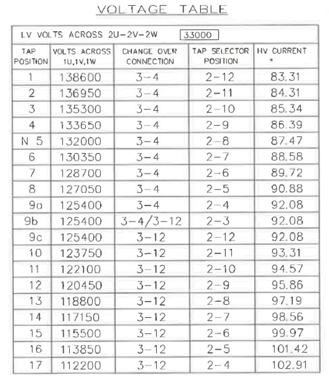
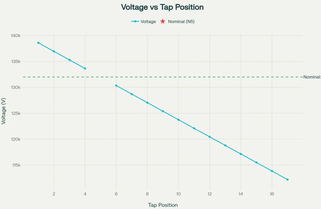
Let’s look at a practical example using the 20 MVA, 132/33 kV transformer shown in the voltage table above. This transformer has an on-load tap changer with 17 tap positions:
- Tap Position 1: 138,600V (Highest voltage, +5.00%)
- Tap Position N5: 132,000V (Nominal/Rated voltage, 0%)
- Tap Position 17: 112,200V (Lowest voltage, -15.00%)
Each tap step changes the voltage by approximately 1,250V (0.95%).
Practical Scenario:
Imagine it’s 9 AM on a weekday, and the industrial area fed by this transformer experiences high demand. The input voltage at the transformer’s primary drops to 130,000V (below the 132,000V nominal). The OLTC’s automatic voltage controller detects this voltage dip. Within seconds, it moves the tap from position N5 to position 6, increasing the number of active primary turns. This adjustment compensates for the low input voltage, maintaining the secondary voltage at the desired 33,000V level.
Later, in the evening, demand drops, and input voltage rises to 135,000V. The controller automatically shifts back to position 3 or 4, reducing the effective primary turns to maintain stable secondary voltage.
Advantages of OLTC
The benefits of on-load tap changers are significant:
- Continuous Voltage Regulation: Adjustments happen without power interruption, maintaining stable voltage 24/7
- Automatic Operation: Modern OLTC systems use automatic voltage regulators (AVR) that monitor voltage in real-time and adjust taps automatically
- Grid Stability: Continuous voltage control prevents voltage sags, swells, and flickers that damage sensitive equipment
- Energy Efficiency: Proper voltage regulation minimizes power losses in the distribution system
- Extended Equipment Life: Stable voltage prevents overvoltage or undervoltage damage to downstream equipment
- Greater Flexibility: Can handle highly dynamic loads and rapid demand changes
Disadvantages of OLTC
- Higher Complexity: The OLTC mechanism is more complex than off-load tap changers, with many moving parts
- Higher Cost: Initial purchase price and installation costs are significantly higher
- Increased Maintenance: Moving parts require regular inspection and maintenance, including oil analysis for oil-cooled OLTCs
- Potential Mechanical Failures: Moving parts can fail due to environmental factors, temperature variations, or contamination
- Risk to Entire Transformer: If the OLTC fails, the entire transformer may need to be taken out of service for repairs
Off-Load Tap Changer (OFLTC)
An off-load tap changer (OFLTC), also called a de-energized tap changer (DETC) or no-load tap changer (NLTC), requires the transformer to be disconnected from the power supply before any tap adjustment can be made. Once de-energized, there’s no load current, and the tap can be changed safely using a simple mechanical switch.
How OFLTC Works
The operation of an off-load tap changer is straightforward:
Step 1: De-energization
The transformer is disconnected from the power supply, and all load current stops flowing.
Step 2: Tap Switching
With no current to worry about, a simple selector switch can now safely move from one tap to another. There’s no arcing, no circulating current, and no need for complex transition impedances.
Step 3: Re-energization
Once the tap change is complete, the transformer is reconnected to the power supply.
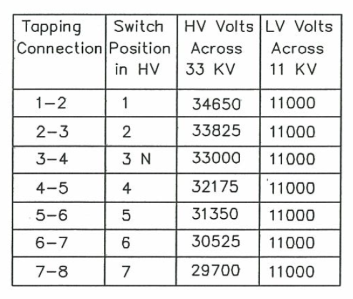
Off Load Tap Changer Voltage Levels at Different Tap Positions for 33/11 kV Transformer
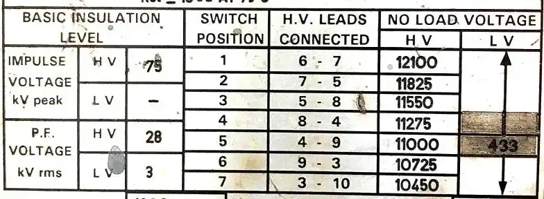
Off Load Tap Changer Voltage Levels at Different Tap Positions for 11/0.433 kV Transformer
Simple Design for Simple Situations
The mechanical design is much simpler than OLTC. Typically, off-load tap changers use:
- A simple center-tapped reactor or selector switch
- Diverter switches (S) that operate without load
- Selector switches (1, 2, 3, etc.) that select different tap points
- No complex arcing contacts or transition resistors
Because there’s no need to handle arcing or circulating current, the components are less sophisticated and more durable.
Real-World Application
Imagine a rural substation serving a small industrial facility with steady, predictable loads. The facility operates on a regular schedule: 8 AM to 5 PM, Monday to Friday, with minimal load variation. An off-load tap changer would be ideal here.
If the facility’s demand never changes significantly, seasonal adjustments might be made only 2-4 times per year:
- Summer: When air conditioning demand peaks, increase the tap to higher settings
- Winter: When heating demand is high, adjust to lower settings
- Maintenance: Tap adjustments can be scheduled during planned maintenance windows or low-demand periods
Since adjustments are infrequent and predictable, the temporary power interruption (usually 10-30 minutes for the tap change procedure) is acceptable and doesn’t disrupt operations.
Advantages of OFLTC
Off-load tap changers offer important benefits for specific applications:
- Simple Mechanical Design: Fewer moving parts mean fewer things that can go wrong
- Lower Cost: Both purchase price and installation costs are significantly lower
- Low Maintenance Requirements: Simple mechanisms need minimal maintenance
- Long Component Life: Fewer complex parts mean longer service life
- Easy to Repair: If problems occur, repairs are usually straightforward
- Cost-Effective for Stable Loads: Perfect for facilities with predictable, steady demand
Disadvantages of OFLTC
However, off-load tap changers have significant limitations:
- Power Interruption Required: The transformer must be de-energized for tap changes, which interrupts service
- Manual Adjustment Typically Required: Most OFLTC systems are manually operated, requiring field personnel to make adjustments
- Reactive Voltage Control: Adjustments are made based on anticipated need, not real-time conditions
- Limited Flexibility: Cannot respond to rapid load changes or unexpected voltage fluctuations
- Service Outages: Each tap change causes a brief power outage, which may be unacceptable in critical applications
Key Differences: OLTC vs. OFLTC
Let’s compare these two technologies side-by-side to help you understand when each is appropriate:
| Feature | On-Load Tap Changer (OLTC) | Off-Load Tap Changer (OFLTC) |
|---|---|---|
| Operation | Changes taps while transformer is energized and carrying load | Requires de-energization before tap changes |
| Power Interruption | None – continuous operation | Temporary interruption required (10-30 minutes typically) |
| Adjustment Type | Automatic (with AVR) or manual | Primarily manual |
| Response Time | Real-time (seconds) | Scheduled or emergency-only |
| Voltage Regulation Range | ±10% (typical 16 steps above and below nominal) | ±5% to ±10% (typically ±8 taps) |
| Complexity | High – sophisticated switching and transition impedance | Low – simple selector switch |
| Cost | High – expensive mechanism and control systems | Low – simple, cost-effective design |
| Maintenance | Higher – regular inspection of moving parts, oil analysis | Minimal – simple mechanical components |
| Applications | Distribution networks, dynamic loads, critical loads | Industrial sites with steady loads, rural areas |
| Switching Time | 40-60 ms for current transfer; 3-10 seconds total operation | N/A (manual, no automatic switching) |
| Moving Parts | Many (contacts, resistors, springs, drive mechanisms) | Few (selector switch) |
| Mechanical Wear | Higher – frequent switching causes wear | Lower – infrequent switching |
Practical Example
Let’s work through a real example to show how voltage regulation actually works in practice.
The 20 MVA, 132/33 kV Transformer Example
Using the voltage table from our reference transformer:
Scenario 1: Morning Peak (High Load)
Time: 6 AM, industrial demand is rising rapidly
- Primary voltage (input): 128,500V (slightly low due to line losses)
- Desired secondary voltage: 33,000V
- Current tap setting: Position 7 (128,700V)
- Current secondary voltage: ~33,045V (slightly high)
Action: The OLTC controller detects that secondary voltage is creeping above 33,000V. It issues a lower command, moving the tap from position 7 to position 8 (127,050V).
Result: Secondary voltage drops back to approximately 33,000V. Voltage now remains stable even as morning loads increase.
Scenario 2: Afternoon Peak (Maximum Load)
Time: 2 PM, peak industrial and commercial activity
- Primary voltage: 125,000V (significant line drop due to heavy load)
- Desired secondary voltage: 33,000V
- Current tap: Position 9a (125,400V)
- Current secondary voltage: ~33,000V (just right)
No action needed. The OLTC controller monitors the system continuously. Because secondary voltage is within the acceptable deadband (typically ±2% of nominal), no tap change is initiated.
Scenario 3: Evening Off-Peak (Low Load)
Time: 8 PM, many businesses have closed, residential loads declining
- Primary voltage: 135,000V (rising because line losses have decreased)
- Desired secondary voltage: 33,000V
- Current tap: Position 8 (127,050V)
- Current secondary voltage: ~34,200V (too high!)
Action: The OLTC detects voltage has risen above the upper deadband limit (typically >33,660V). After a time delay of 30-60 seconds (to prevent hunting due to momentary fluctuations), it issues a raise command, moving the tap from position 8 to position 3 (135,300V).
Result: Secondary voltage returns to ~33,000V. The OLTC has prevented overvoltage that could damage sensitive electronic loads.
Voltage Percentage
In the example above, notice that each tap position changes voltage by approximately 0.95%. Here’s how this works:
\(\text{Voltage Change (\%)} = \frac{\text{Voltage Step}}{{\text{Nominal Voltage}}} \times 100\)
For our transformer:
\(\text{Voltage Change (\%)} = \frac{1,250\text{ V}}{132,000\text{ V}} \times 100 = 0.95\%\)
This formula helps you understand how voltage adjustments scale with different transformer ratings. A 1,250V step on a 132 kV transformer is a small percentage adjustment, but it’s significant enough to maintain stable voltage across the distribution system.
Why Modern Power Systems Rely on OLTC
Most modern power transformers in distribution systems use on-load tap changers because of the increasingly dynamic nature of power grids. Here’s why:
Grid Modernization and Renewable Energy
Modern grids integrate distributed renewable sources like solar and wind, which generate variable power throughout the day. Solar generation peaks at midday then drops quickly as the sun sets. Wind generation varies minute-to-minute based on wind speed. These sources create rapid voltage fluctuations that only continuous, real-time voltage regulation can handle.
An OFLTC cannot respond to these rapid changes—it would require constant manual intervention or cause frequent service outages.
Industrial Loads and Demand Response
Modern industrial facilities use variable frequency drives, power electronic equipment, and automated processes that create rapidly changing loads. Manufacturing equipment that draws full current one moment and minimal current the next second would cause voltage swings that an OFLTC couldn’t manage.
Critical Infrastructure Requirements
Hospitals, data centers, emergency services, and other critical facilities cannot tolerate even brief power outages. An OFLTC would be completely unsuitable for these applications. OLTC allows voltage adjustment without any service interruption.
Voltage Quality Standards
Electrical standards (like IEEE 519 and IEC 61000) require voltage to stay within ±10% of nominal. OLTC systems with automatic controllers ensure compliance with these standards continuously. Manual OFLTC systems cannot guarantee this compliance.
When OFLTC Is Still Used
Despite OLTC’s advantages, off-load tap changers are still deployed in specific situations:
1. Dry-Type Transformers in Controlled Environments: Dry-type transformers in buildings, where taps might be adjusted during maintenance windows or load planning changes (perhaps monthly or quarterly).
2. Rural Distribution Transformers: Serving small communities with stable, predictable seasonal demand where adjustments happen just 2-4 times yearly.
3. Cost-Sensitive Applications: Where budgets are extremely limited and load variations are minimal—sacrificing voltage regulation quality for low capital cost.
4. Specialized Industrial Applications: Some industrial sites with constant, steady-state processes may use OFLTC if loads truly never vary significantly.
5. Older Systems: Existing systems where transformers are already installed and operational. Replacement with OLTC might not be economically justified if the transformer isn’t reaching end-of-life.
How OLTC Really Works?
To fully understand tap changers, let’s peek inside the mechanism. An OLTC typically contains:
1. Selector Switch
This component selects which tap position you want to move to. It operates at no-load (no current flowing through it), so it doesn’t need to handle arcing. It’s essentially a rotary selector that pre-positions the next tap before load transfer occurs.
2. Diverter Switch
This is the workhorse of the OLTC. The diverter switch actually carries the load current and smoothly transfers it from one tap to another. It uses sophisticated arcing contacts because it operates under full load current.
3. Transition Impedance
This is typically a resistor (resistive OLTC) or reactor (reactor-type OLTC) that’s inserted momentarily during current transfer. Its job is to:
- Limit the circulating current between taps when both are momentarily active
- Prevent short circuits during transition
- Prevent excessive arcing
Most modern high-capacity OLTCs use reactor-type transition impedances because they’re more efficient (lower loss) than resistive types.
4. Drive Mechanism
A motor-driven mechanism controlled by an Automatic Voltage Regulator (AVR). The AVR continuously monitors secondary voltage and issues tap-up or tap-down commands as needed.
5. Spring Energy Accumulator
This stores mechanical energy to operate the diverter switch quickly and reliably, independent of the motor’s motion. It ensures fast, consistent switching every time.
6. Control System
Modern OLTCs include sophisticated microprocessor-based controllers that:
- Monitor voltage in real-time
- Calculate the required tap position
- Prevent unnecessary switching (hunting)
- Implement time delays to avoid reacting to momentary fluctuations
- Log operations for maintenance analysis
- Coordinate with other tap changers in the system
Tap Changer Maintenance and Monitoring
OLTC Maintenance
Regular maintenance is essential for reliable OLTC operation:
Oil Analysis and Replacement
Oil-immersed OLTCs require periodic oil analysis to check for:
- Water content (indicates possible seal leaks)
- Dissolved gases (indicate arcing or overheating)
- Contamination (particles that cause wear)
- Acid number (indicates oil degradation)
Mechanical Inspection
- Visual inspection of contacts for wear or pitting
- Spring tension verification
- Drive mechanism lubrication and inspection
- Electrical resistance measurement of transition impedances
Operation Count Monitoring
Tracking the number of tap changes helps predict maintenance needs. Typically, modern contacts are rated for 100,000+ mechanical operations, but more frequent switching may warrant earlier inspection.
OFLTC Maintenance
Off-load tap changers require minimal maintenance:
- Occasional mechanical inspection for corrosion or blockage
- Lubrication of moving parts (if not sealed)
- Electrical continuity checks
- Physical inspection of connections for looseness
Conclusion
Understanding the differences between on-load and off-load tap changers is crucial for engineers, technicians, and facility managers involved in power system design and operation.
As electrical grids evolve toward greater complexity and renewable integration, on-load tap changers will become even more critical for grid stability and power quality. However, off-load tap changers will continue to serve cost-sensitive, simple applications effectively.
The key is matching the right technology to your specific needs—and now you have the knowledge to make that decision.