The Capacitor Start Capacitor Run (CSCR) motor, also known as the two-value capacitor motor is one of the most advanced and efficient designs in the family of single-phase induction motors. This motor type has revolutionized applications requiring both high starting torque and superior running efficiency. This makes it an indispensable component in modern industrial and commercial equipment.
In this technical guide, we will discuss the CSCR motor’s working principles, construction, and characteristics which is essential for electrical engineering students and professionals who design, maintain, or troubleshoot electrical systems.
1. The Need for CSCR Motors
Single-phase induction motors are inherently not self-starting because a single-phase AC supply cannot produce a rotating magnetic field on its own. The CSCR motor overcomes this limitation through an ingenious dual-capacitor design that provides optimal performance during both startup and continuous operation.
Unlike simpler motor designs that compromise either starting torque or running efficiency, the CSCR motor achieves excellence in both parameters. This unique capability makes it the preferred choice for applications where performance cannot be sacrificed.
2. Construction and Components of CSCR Motor
2.1 Core Structural Elements
The CSCR motor consists of several key components that work in together to deliver superior performance:
2.1.1 The Rotor
The rotor is of the squirrel cage type identical to those used in three-phase induction motors. It features aluminum or copper bars that are short-circuited at both ends by end rings. This robust construction provides durability and reliable performance under various operating conditions.
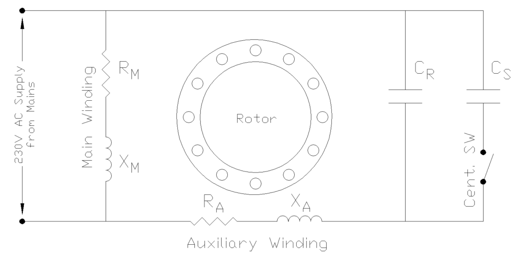
2.1.2 The Stator and Windings
The stator houses two distinct windings that are spatially displaced by 90 electrical degrees:
- Main Winding (Running Winding): Constructed with heavier gauge wire and more turns, this winding is designed to carry current continuously during motor operation.
- Auxiliary Winding (Starting Winding): Uses slightly finer wire with fewer turns and remains energized throughout the motor’s operation.
2.2 The Dual-Capacitor System
What distinguishes the CSCR motor from other single-phase motor types is its unique two-capacitor configuration:
2.2.1 Starting Capacitor (Cs)
- Large-value, short-time rated electrolytic capacitor
- Typically ranges from 70 to 400 microfarads or higher
- Provides the substantial phase shift necessary to generate high starting torque
- Values approximately 10 to 15 times larger than the running capacitor
2.2.2 Running Capacitor (Cr)
- Smaller-value, continuous-duty capacitor
- Typically ranges from 5 to 100 microfarads
- Constructed using oil-filled paper or metallized film technology
- Remains permanently connected in series with the auxiliary winding
- Provides continuous phase correction and improves power factor during steady-state operation
2.3 Switching Mechanism
A centrifugal switch serves as the important component that transitions the motor from starting to running mode. This mechanical switch is mounted on the motor shaft and operates based on centrifugal force.
When the motor reaches approximately 75-80% of its synchronous speed the centrifugal switch opens which disconnects the starting capacitor from the circuit while leaving the running capacitor and auxiliary winding energized.
3. Working Principle and Operation of CSCR Motor
3.1 Starting Phase Operation
When power is initially applied to a CSCR motor, both capacitors are connected in parallel through the closed centrifugal switch, creating a combined capacitance value equal to the sum of both individual capacitances. This configuration develops high starting torque characteristic of CSCR motors.
The large total capacitance creates a leading current in the auxiliary winding that is displaced by more than 90 degrees from the main winding current. This phase difference generates a strong rotating magnetic field that produces high starting torque ranging from \(300%\) to \(400%\) of the full-load torque.
The mathematical relationship of this behavior can be expressed through the capacitive reactance formula:
\(X_C=\frac{1}{2\pi fC}\)
Where a larger capacitance value \(C\) results in lower reactance and higher current flow.
The electromagnetic interaction between the stator’s rotating magnetic field and the induced currents in the rotor’s squirrel cage bars generates torque according to the fundamental principle:
\(\tau=kI_s I_m sin\alpha\)
where \(I_s\) is the auxiliary winding current, \(I_m\) is the main winding current, and \(\alpha\) is the phase angle between them.
During starting, with both capacitors engaged the phase angle exceeds 90 degrees which maximizes the torque production.
3.2 Transition to Running Mode
As the rotor accelerates and approaches 75-80% of synchronous speed, the centrifugal switch mechanism activates due to increased centrifugal force acting on the switch weights. This mechanical action opens the switch contacts and removes the starting capacitor from the circuit. The motor now operates with only the running capacitor in series with the auxiliary winding.
With the smaller running capacitor, the phase angle between the main and auxiliary winding currents approaches exactly 90 degrees creating nearly balanced two-phase operation. This phase relationship eliminates the backward rotating magnetic field component that exists in other single-phase motor types and results in improved efficiency, better power factor, and smoother torque production.
3.3 Steady-State Running Operation
During continuous operation, the CSCR motor functions essentially as a balanced two-phase motor with the running capacitor providing permanent phase correction. The auxiliary winding and running capacitor remain energized throughout the motor’s operation. This delivers several operational advantages compared to motors where the auxiliary winding is disconnected after starting.
The power factor during running conditions ranges from \(0.85\) to \(0.95\), which is higher than other single-phase motor types. This improved power factor results from the continuous phase compensation provided by the running capacitor which reduces the reactive power drawn from the supply and improves overall system efficiency.
4. Phasor Diagram of Capacitor Start Capacitor Run Motor
4.1 During Starting
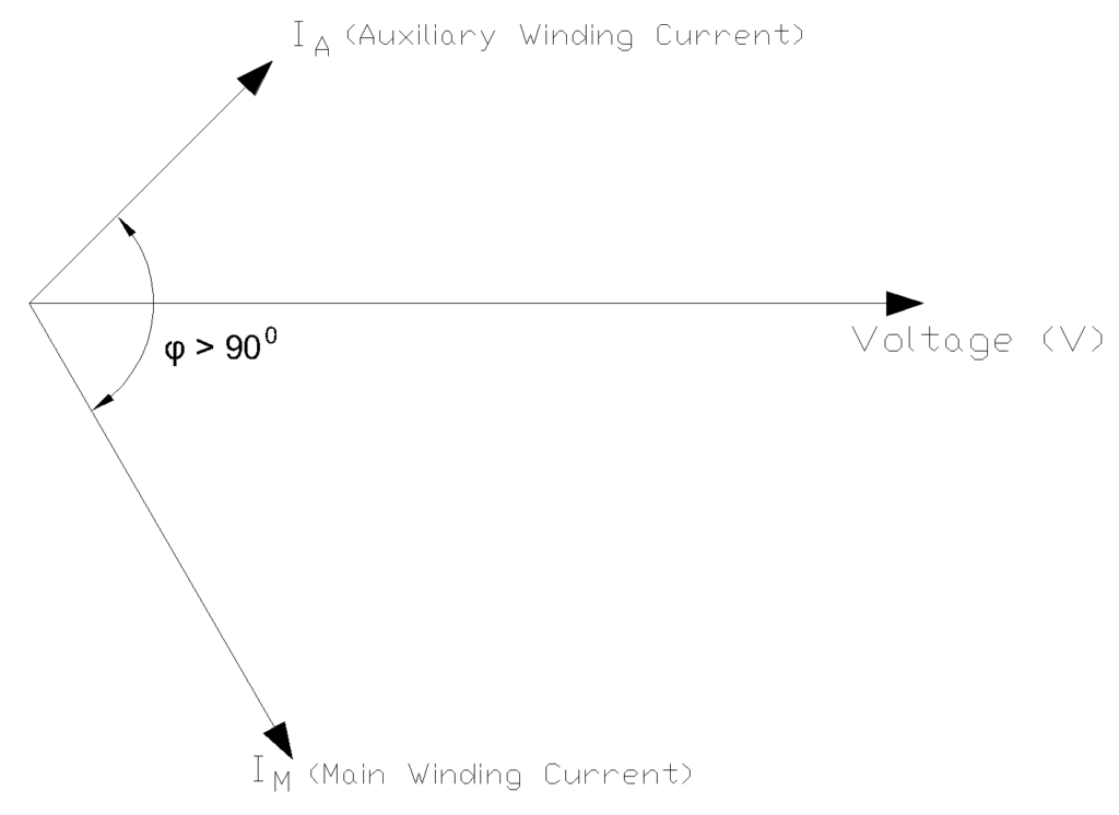
During starting, when both capacitors are in the circuit, the auxiliary winding current \(I_A\) leads the supply voltage and creates a phase angle \(\phi\) greater than \(90\) degrees between the main and auxiliary winding currents. This large phase displacement generates strong rotating magnetic field required for high starting torque.
4.2 During Running
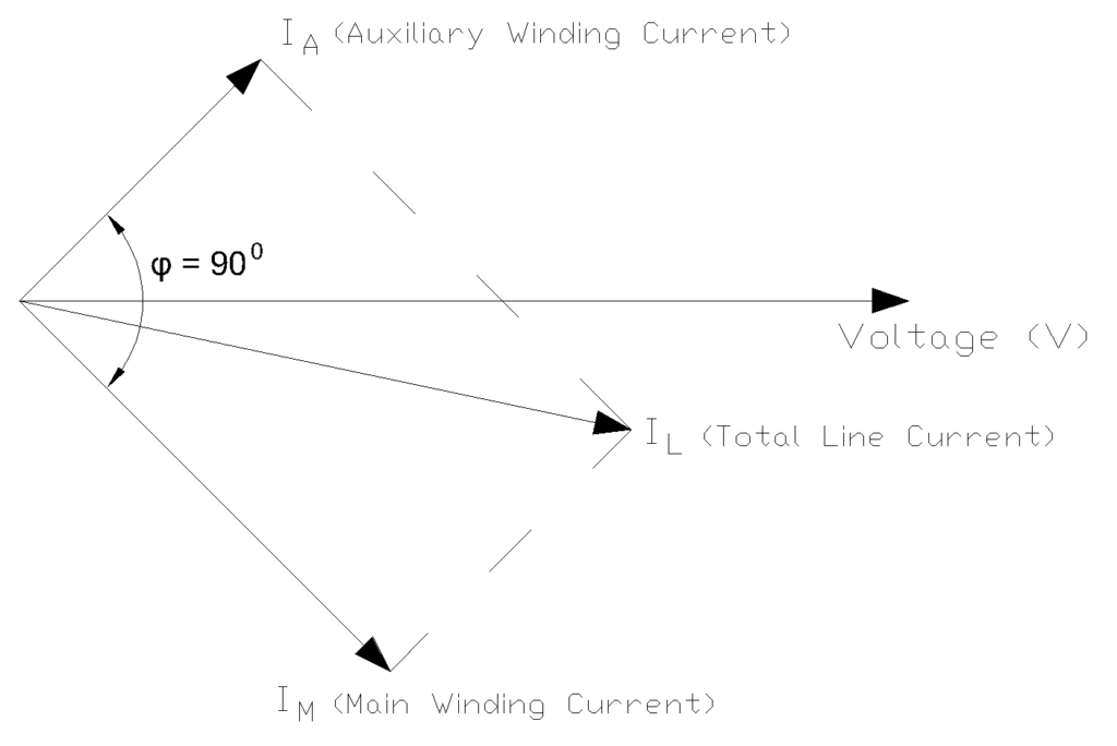
After the centrifugal switch opens and disconnects the starting capacitor, the phase relationship changes. With only the running capacitor in circuit, the phase angle approaches exactly \(90\) degrees, creating the optimal condition for balanced two-phase operation. The total line current \(I_L\) becomes the vector sum of the main winding current \(I_M\) and the auxiliary winding current \(I_A\), with the magnitude and phase carefully balanced to minimize reactive power consumption.
5. Torque-Speed Characteristics
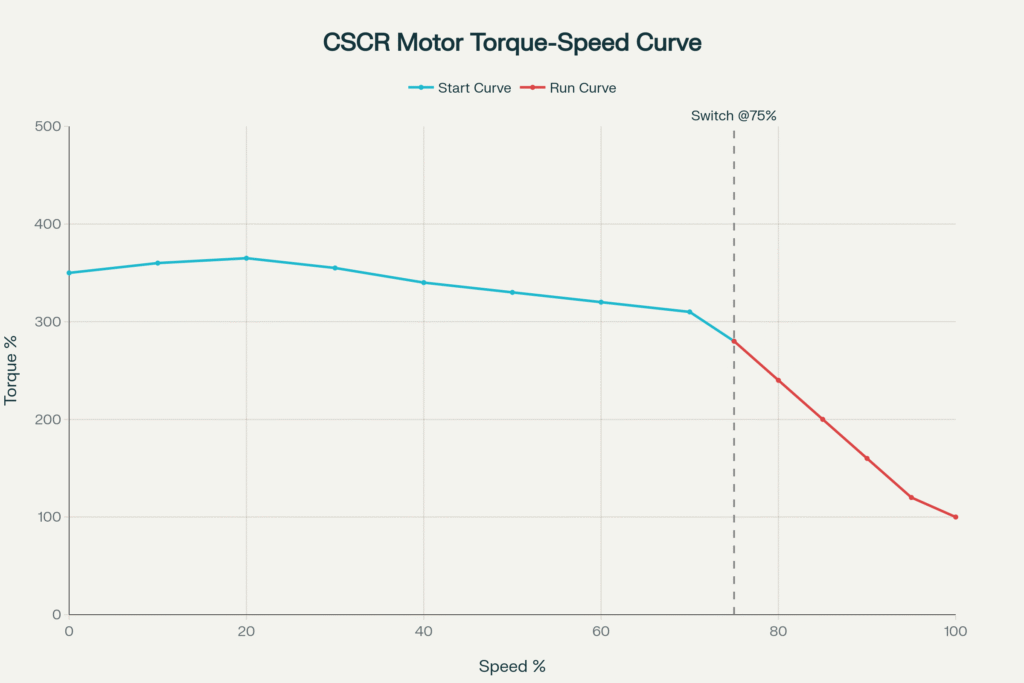
At standstill (zero speed), the motor develops very high starting torque, typically 300% to 400% of the full-load torque. This characteristic makes Capacitor Start Capacitor Run motors ideal for applications requiring the motor to start under heavy load conditions.
As the motor accelerates from standstill, the torque initially remains high and may even increase slightly in the lower speed range. This behavior ensures smooth, rapid acceleration even when driving high-inertia loads. The torque continues at elevated levels until the motor reaches approximately 75-80% of synchronous speed, at which point the centrifugal switch operates.
When the starting capacitor is disconnected, there is a noticeable but not severe drop in the torque curve. However, the motor maintains sufficient torque to continue accelerating smoothly to its rated operating speed. At synchronous speed, the motor settles to its rated full-load torque, which is designed to match the application requirements.
6. Capacitor Selection and Sizing
6.1 Starting Capacitor Calculations
The starting capacitor value can be estimated using the following formula:
\(C_{start}=\frac{5\times I_{FL}}{2\pi fV}\)
where \(C_{start}\) is the starting capacitance in microfarads, \(I_{FL}\)is the full-load current in amperes, \(f\) is the frequency in hertz, and \(V\) is the voltage in volts.
An alternative approach based on motor power uses:
\(C_{start}=\frac{P\times \eta \times 1000}{V^2\times f}\)
where \(P\) is motor power in watts, \(η\) is efficiency as a decimal, \(V\) is voltage, and \(f\) is frequency.
For example, a 2 kW motor operating at \(230V\), \(50\, Hz\), with 80% efficiency would require:
\(C_{start}=\frac{2000\times 0.8\times 1000}{230^2\times 50}=60.5\mu F\)
Starting capacitors are typically rated for \(70\) to \(400\) microfarads or higher, with voltage ratings of \(125V\), \(250V\), or \(330V\) AC depending on the application. The voltage rating must equal or exceed 1.5 times the motor’s operating voltage to provide an adequate safety margin.
6.2 Running Capacitor Calculations
The running capacitor is sized to provide optimal phase correction during continuous operation. The running capacitor value can be calculated using:
\(C_{run}=\frac{2.5\times I_{FL}}{2\pi fV}\)
which typically yields a value approximately one-fifth to one-tenth of the starting capacitor.
Running capacitors typically range from 5 to 100 microfarads and are rated for continuous duty operation. They must have voltage ratings of 370V or 440V AC to withstand continuous operation and voltage transients. The capacitor material is typically metallized polypropylene film or oil-impregnated paper, both capable of reliable continuous operation.
7. Comparison with Other Single-Phase Motor Types
7.1 CSCR vs. Capacitor Start Induction Run (CSIR) Motors
CSIR motors use a single starting capacitor that is disconnected after startup with the auxiliary winding also being switched out of the circuit. This simpler design reduces cost but sacrifices running efficiency and power factor compared to CSCR motors. CSIR motors typically achieve running efficiencies of 60-75% compared to 75-85% for CSCR motors.
The starting torque of CSIR motors, while good at 200-350% of full load, generally does not match the 300-400% capability of CSCR motors. However, CSIR motors are less expensive and have lower maintenance requirements due to having only one capacitor. For applications not requiring the highest efficiency or starting torque, CSIR motors may be more economical.
| Parameter | CSCR Motor | CSIR Motor |
|---|---|---|
| Starting Torque | 300-400% of full load | 200-350% of full load |
| Running Efficiency | 75-85% | 60-75% |
| Auxiliary Winding | Remains energized | Disconnected after start |
| Cost | Higher | Lower |
| Maintenance | More complex | Simpler |
7.2 CSCR vs. Permanent Split Capacitor (PSC) Motors
PSC motors use a single capacitor that remains permanently connected similar to the running capacitor in a CSCR motor. However, PSC motors lack the starting capacitor which results in much lower starting torque only 50-100% of full load. This limitation restricts PSC motors to applications with light starting loads.
PSC motors have the advantage of simplicity, requiring no centrifugal switch and having only one capacitor to maintain. They operate quietly and smoothly due to the balanced two-phase operation. Running efficiency of PSC motors is moderate, typically 60-70%, falling between CSIR and CSCR motors. For applications such as fans, blowers, and other light-starting loads, PSC motors offer a reliable, low-maintenance solution.
| Parameter | CSCR Motor | PSC Motor |
|---|---|---|
| Starting Torque | 300-400% of full load | 50-100% of full load |
| Running Efficiency | 75-85% | 60-70% |
| Capacitors | Two (starting + running) | One (permanent) |
| Centrifugal Switch | Required | Not required |
| Noise Level | Low | Very low |
7.3 CSCR vs. Split-Phase Motors
Split-phase motors is the simplest and least expensive single-phase motor type. They use only resistance differences between windings to create the starting phase shift. Starting torque is moderate at 150-200% of full load and running efficiency is low at 50-60%. The power factor of split-phase motors is poor typically 0.50-0.65.
CSCR motors outperform split-phase motors in every performance metric but at substantially higher cost. Split-phase motors are limited to fractional horsepower ratings under 1 HP, while CSCR motors can be built in ratings up to 20 HP. For small, cost-sensitive applications where performance is not important, split-phase motors remain a viable option.
| Parameter | CSCR Motor | Split-Phase Motor |
|---|---|---|
| Starting Torque | 300-400% of full load | 150-200% of full load |
| Running Efficiency | 75-85% | 50-60% |
| Power Factor | 0.85-0.95 | 0.50-0.65 |
| Power Rating | Up to 20 HP | Typically under 1 HP |
| Cost | Higher | Lowest |
8. Applications of CSCR Motors
- Air compressors require high starting torque to overcome initial compression loads and the efficient running operation during sustained compression cycles. The motor’s ability to handle frequent start-stop cycles makes it ideal for compressors with automatic pressure control.
- Refrigeration and air conditioning systems rely heavily on Capacitor Start Capacitor Run motors for compressor drives. The compressor must start against system pressure requires substantial starting torque, while the continuous running operation demands high efficiency to minimize energy costs. CSCR motors excel in both aspects, making them the standard choice for these applications.
- Pumping equipment, particularly for high-head applications or systems that start with the discharge valve closed, requires the high starting torque that CSCR motors provide.
- Conveyor systems that start under load benefit from the CSCR motor’s high starting torque. The smooth torque production during running operation reduces wear on conveyor belts and mechanical components.
- Machine tools such as lathes, milling machines, and grinders require the smooth, vibration-free operation that CSCR motors provide.
- Industrial ventilation and HVAC systems in commercial buildings utilize CSCR motors when high airflow capacity requires larger fan motors.
9. Advantages and Disadvantages of CSCR Motors
9.1 Advantages
Capacitor Start Capacitor Run motors offer numerous advantages that make them the preferred choice for demanding applications.
- The exceptional starting torque capability ranging from 300% to 400% of full-load torque enables these motors to start heavy loads and overcome significant inertia. This characteristic is particularly valuable in applications involving pumps, compressors, and conveyors that may experience high breakaway torque requirements.
- The high running efficiency ranging from 75% to 85% significantly exceeds that of other single-phase motor types. This efficiency advantage translates directly into reduced energy consumption and lower operating costs over the motor’s lifetime.
- Superior power factor during running conditions between 0.85 and 0.95 is another significant advantage. This high power factor reduces reactive power consumption, decreases line losses, and may help avoid utility power factor penalties in commercial installations.
- Smooth and quiet operation results from the constant torque production and absence of significant pulsations. This characteristic makes CSCR motors ideal for installations where noise is a concern, such as in hospitals, studios, offices, and residential applications.
- The ability to handle frequent starts without excessive heating or stress distinguishes CSCR motors from many other types.
9.2 Disadvantages
Despite their superior performance, CSCR motors have several disadvantages that must be considered.
- The higher initial cost compared to simpler motor types results from the dual-capacitor system, centrifugal switch, and more complex construction.
- Increased complexity introduces more failure points. The centrifugal switch mechanism can fail due to wear, contamination, or improper adjustment. Both capacitors require periodic inspection and replacement with the starting capacitor particularly prone to failure due to the high stress it experiences during each start cycle.
- Higher maintenance requirements stem from the need to inspect and replace capacitors, check the centrifugal switch operation, and ensure proper electrical connections.
- Space requirements for mounting two capacitors can be a constraint in compact installations.
10. Conclusion
The construction, operation, and maintenance requirements of Capacitor Start Capacitor Run motors is essential for electrical engineers involved in motor specification, installation, or maintenance. Proper capacitor selection, correct installation practices, and regular maintenance ensure these motors deliver their full performance potential throughout their operational lifetime. As single-phase power systems continue to predominate in residential and light commercial installations, and as efficiency standards become increasingly stringent, the CSCR motor’s superior performance characteristics ensure its continued relevance in modern electrical systems.