In modern electrical power systems, transformers face an unprecedented challenge from non-linear loads that generate electrical harmonics. These harmonic currents and voltages, superimposed on the fundamental 50 Hz or 60 Hz frequency, cause transformers to overheat, lose efficiency, and age prematurely.
Proper understanding of harmonics in transformers is important for maintaining reliable power distribution, equipment longevity, and complying with international standards like IEEE 519.
In this technical guide we will explain what harmonics are, why they affect transformers so severely, how to calculate their impact, and what proven mitigation strategies can protect your electrical infrastructure.
What Are Harmonics in Transformers?
Harmonics are sinusoidal voltage or current components at frequencies that are integer multiples of the fundamental supply frequency. In a 50 Hz power system, the fundamental frequency is 50 Hz, and harmonics occur at 150 Hz (3rd), 250 Hz (5th), 350 Hz (7th), 450 Hz (9th), and so on. In a 60 Hz system, they occur at 180 Hz (3rd), 300 Hz (5th), 420 Hz (7th), etc.
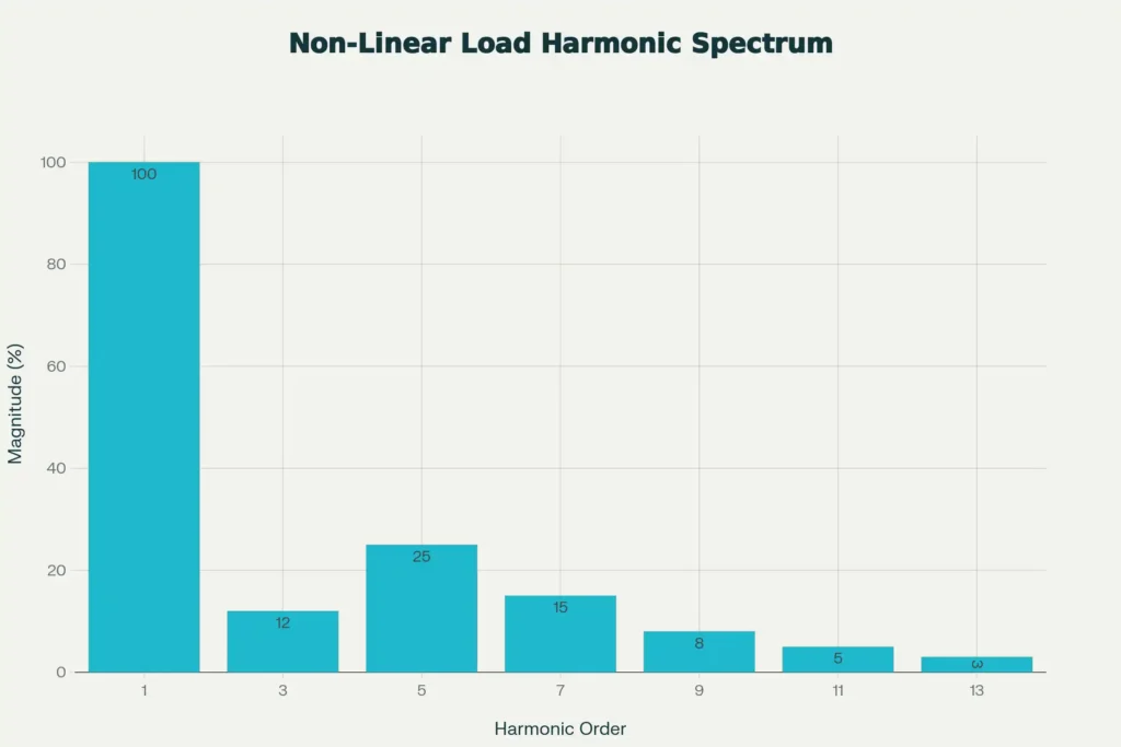
In an ideal sinusoidal power system without harmonics, the current and voltage waveforms would be perfectly smooth, with only the fundamental frequency component. However, non-linear loads such as variable frequency drives (VFDs), power electronics, rectifiers, and energy-efficient lighting do not draw current in a sinusoidal manner. Instead, they draw current in pulses or distorted waveforms that contain multiple frequency components when analyzed using Fourier series.
Total Harmonic Distortion (THD) is the standard metric used to quantify the harmonic content in a system. It expresses the magnitude of all harmonic components as a percentage of the fundamental frequency:
\(THD = \frac{\sqrt{(V_3^2 + V_5^2 + V_7^2 + V_9^2 + …)}}{V_1} × 100\%\)
Where V₁ is the fundamental component and V₃, V₅, V₇ are the harmonic components.
Why Transformers Are Affected by Harmonics
Transformers are designed to operate efficiently at the fundamental frequency (50 or 60 Hz) under sinusoidal current and voltage conditions. When transformers encounter harmonic currents, several physical phenomena occur that degrade performance and cause problems.
1. Harmonic Heating: Skin Effect and Eddy Current Losses
When current flows through a conductor at the fundamental frequency, it distributes relatively uniformly across the conductor’s cross-section. However, at higher harmonic frequencies, a phenomenon called skin effect causes current to flow preferentially at the surface of the conductor, concentrating in a thin outer layer.
This skin effect increases the AC resistance of the conductor at higher frequencies compared to its DC resistance:
\(R_{AC} = R_{DC} \times (1 +\) skin effect factor \()\)
Since power losses in a conductor are proportional to I²R (Joule heating), the increased resistance at harmonic frequencies causes significantly higher losses.
For a 5th harmonic current of the same magnitude as the fundamental, the losses would be approximately 25 times higher \((5^2 × R_{AC})\).
Additionally, harmonic currents induce circulating currents in the transformer’s core material and structural components a phenomenon called eddy current losses. These losses increase proportionally to the square of both the frequency and the current magnitude:
\(P_{eddy} ∝ f^2 × I^2\)
This means that even small amounts of 5th harmonic current can generate substantial eddy current losses. A 5th harmonic generates losses proportional to 25 times the fundamental, a 7th harmonic generates losses proportional to 49 times, and so on.
2. Transformer Core Saturation and Flux Distortion
Under normal sinusoidal conditions, the magnetic flux in a transformer core rises and falls smoothly, never exceeding the design saturation limit. However, harmonic currents create additional flux components at different frequencies. When these harmonic fluxes combine with the fundamental flux, they can temporarily push the core deeper into the saturation region.
Once the core enters saturation, its permeability drops and the relationship between current and flux becomes highly nonlinear. This can cause:
- Distortion of the core magnetization curve
- Generation of additional harmonics (harmonic amplification)
- Increased magnetizing current
- Transformer damage if saturation is severe
Classification of Harmonics: Types and Characteristics
| Harmonic Type | Frequency (50 Hz) | Typical Magnitude | Zero Sequence | Primary Sources |
|---|---|---|---|---|
| Fundamental | 50 Hz | 100% (Reference) | No | Sinusoidal supply |
| Triplen (3rd, 9th, 15th, 21st) | 150, 450, 750, 1050 Hz | 5-15% (in neutral) | Yes (Zero Sequence) | Single-phase rectifiers, lighting, SMPS |
| Non-Triplen Odd (5th, 7th, 11th, 13th) | 250, 350, 550, 650 Hz | 5-30% of fundamental | No (Positive/Negative) | 3-phase converters, VFDs, welding |
| Even Harmonics (2nd, 4th, 6th) | 100, 200, 300 Hz | < 5% (less common) | No | DC-AC conversion (rare) |
| High-Order (>13th) | >650 Hz | < 3% (decreasing) | Mixed | Complex loads, grid transients |
Triplen Harmonics: A Concern for Transformers
Triplen harmonics (3rd, 9th, 15th, 21st—multiples of 3) deserve special attention because they behave completely differently from other harmonics in three-phase systems. While fundamental frequency currents on the three phases are 120° out of phase and cancel in the neutral conductor, triplen harmonics are in phase on all three phases.
This means that triplen harmonic currents add up in the neutral conductor rather than canceling:
\(I_{neutral} = 3 × I_{triplen}\) (per phase)
If each phase has a 20 A triplen harmonic component, the neutral conductor must carry 60 A of current. This creates several critical problems:
- Neutral conductor overheating (“hot neutral” condition)
- Voltage rise on the neutral relative to ground
- Equipment damage and fire hazards
- Phase-to-ground voltage imbalance affecting sensitive electronic loads
Effects of Harmonics on Transformers
The presence of harmonic currents in transformers creates numerous detrimental effects that can significantly reduce equipment life and system reliability.
| Effect | Mechanism | Severity |
|---|---|---|
| Increased Copper Losses (I²R) | Skin effect increases AC resistance at high frequencies | High (∝ h² frequency) |
| Increased Eddy Current Losses | Higher frequency eddy currents induce larger circulating currents | Very High (∝ h² frequency) |
| Core Saturation | Harmonic flux components can push core into saturation region | Medium |
| Winding Temperature Rise | Additional losses convert to heat in windings | Very High |
| Reduced Efficiency | Increased losses reduce output power available to load | Medium |
| Transformer Derating | Operating temperature limits require reducing rated power | High |
| Mechanical Stress/Vibration | Electromagnetic forces at harmonic frequencies increase vibration | Medium |
| Insulation Aging | Higher operating temperature accelerates insulation degradation | Very High (long-term) |
| Neutral Conductor Overheating | Triplen harmonics add in neutral (3× phase harmonic) | Critical for triplen |
| Increased Audible Noise | Vibration from magnetic forces produces audible hum | Low (nuisance) |
Practical Example: Transformer Overheating Due to Harmonics
Consider a 500 kVA transformer supplying a facility with significant electronic loads. Measurements show:
- Fundamental current: 300 A (RMS)
- 5th harmonic: 75 A (RMS) (25% of fundamental)
- THD: 34.28%
Under these conditions, the transformer generates approximately 4-5 times more heat than it would with sinusoidal current alone.
To prevent overheating and insulation damage, the transformer’s rated load capacity must be reduced (derated) proportionally. Instead of being able to supply the rated 500 kVA, it can only safely supply approximately 100 kVA—a loss of 80% of usable capacity.
Short-Term vs. Long-Term Effects
Short-term effects of harmonic heating include:
- Immediate temperature rise beyond rated limits
- Nuisance tripping of thermal overload protections
- Reduced power delivery capacity
Long-term effects are even more serious:
- Accelerated insulation aging (doubling or tripling the aging rate)
- Reduced transformer lifespan from 20-30 years to 5-10 years
- Eventual insulation breakdown and catastrophic failure
- Hot spots that can lead to transformer fires
Nonlinear Loads and Harmonic Generation
| Load Type | Primary Harmonics Generated | Typical THD | Typical Magnitude Factor |
|---|---|---|---|
| Switch-Mode Power Supply (SMPS) | 3rd, 5th, 7th, 9th (odd) | 40-90% | K-9 to K-13 |
| Variable Frequency Drive (VFD) | 5th, 7th, 11th, 13th | 30-50% | K-9 to K-20 |
| Adjustable Speed Drive (ASD) | 5th, 7th, 11th, 13th | 20-40% | K-9 to K-13 |
| Arc Welding Equipment | 3rd, 5th, 7th (irregular) | 20-60% (varies) | K-9 to K-20 |
| Rectifier (6-pulse) | 5th, 7th, 11th, 13th | 40-60% | K-13 to K-20 |
| Rectifier (12-pulse) | 11th, 13th, 23rd, 25th | 15-25% | K-4 to K-9 |
| LED/Electronic Ballasts | 3rd, 5th, 7th, 9th | 20-50% | K-9 to K-13 |
| Uninterruptible Power Supply (UPS) | Multiple (depends on design) | 5-15% | K-4 to K-9 |
| Thyristor-Based Controls | 3rd, 5th, 7th, 9th, 11th | 20-80% | K-13 to K-40 |
| Microwave/Induction Heating | 3rd, 5th, 7th (multiple peaks) | 15-40% | K-9 to K-13 |
K-Factor Ratings: Selecting the Right Transformer for Harmonic Environments
The K-factor is a numerical rating that indicates a transformer’s ability to withstand the thermal effects of harmonic currents without overheating. It is defined mathematically as:
\(K = Σ(\frac{I_n}{I_1})^2 \times n^2\)
Where:
- Iₙ is the RMS current of the nth harmonic
- I₁ is the RMS current of the fundamental frequency
- n is the harmonic order number
The higher the K-factor, the greater the transformer’s resistance to harmonic heating.
| K-Factor Rating | Load Type | Typical Applications | Derating Factor |
|---|---|---|---|
| K-1 (Standard) | Linear loads only | Resistive loads, motors, standard lighting | 1.0 (No derating) |
| K-4 | Moderate harmonic content (10-20%) | Small offices, retail with some electronics | 0.25 (25% derating) |
| K-9 | Mixed linear and nonlinear loads | Mixed facilities with some VFDs | 0.11 (11% derating) |
| K-13 | High harmonic content (20-40%) | Industrial plants with multiple VFDs, welding | 0.08 (8% derating) |
| K-20 | Very high harmonic levels (40-60%) | Data centers, heavy electronics usage | 0.05 (5% derating) |
| K-30 | Extreme harmonic environments (>60%) | Large industrial complexes, severe rectifier loads | 0.03 (3% derating) |
| K-40+ | Ultra-severe harmonic distortion | Specialized industrial applications | 0.02 (2% derating) |
| HMT (Harmonic Mitigating) | Special design for extreme triplen harmonics | Hospital, semiconductor, high triplen loads | Special calculation required |
How to Select the Right K-Factor
The appropriate K-factor depends on your facility’s load composition:
- For predominantly linear loads (traditional motors, resistive heating, standard magnetic lighting): K-1 transformer is sufficient
- For mixed loads with some electronic equipment (offices, retail): K-4 to K-9 transformer
- For heavy electronics and adjustable drives (manufacturing plants, data centers): K-13 to K-20 transformer
- For extreme harmonic environments (multiple welding operations, semiconductor facilities): K-20 to K-40+ transformer
IEEE 519-2014: Harmonic Limits and Compliance Standards
IEEE Standard 519-2014, “Recommended Practice and Requirements for Harmonic Control in Electric Power Systems,” establishes limits for both current and voltage harmonic distortion. These limits depend on the voltage level and are designed to protect equipment and maintain power quality.
| Voltage Category | Individual Voltage Harmonic Limit | Total Voltage Distortion (THD-V) | Current Distortion Limit | Application |
|---|---|---|---|---|
| < 1 kV | 8.0% | 8.0% | TDD < 20% (most cases) | Residential and commercial |
| 1 kV to 69 kV | 3.0% | 5.0% | TDD < 15% (depends on SCR) | General distribution |
| 69 kV to 138 kV | 1.5% | 2.5% | TDD < 10% | Sub-transmission |
| > 138 kV | 1.0% | 1.5% | TDD < 5% | Transmission and interconnection |
These standards ensure that harmonic levels remain within acceptable ranges that do not cause premature equipment failure or power quality issues. Most practical systems aim to keep THD below 5% to ensure good performance and equipment compatibility.
Practical Example for Calculating Harmonic Impact
Let’s work through a detailed calculation showing how to evaluate harmonics in a real transformer installation:
Given Data:
- Transformer Rating: 500 kVA
- Primary Current (Fundamental): 300 A
- 3rd Harmonic Current: 40 A
- 5th Harmonic Current: 75 A
- 7th Harmonic Current: 50 A
- 9th Harmonic Current: 25 A
- 11th Harmonic Current: 15 A
Step 1: Calculate THD
\(THD = \frac{\sqrt{(40^2 + 75^2 + 50^2 + 25^2 + 15^2)}}{300} \times 100\%\)
\(THD = \frac{\sqrt{(1600 + 5625 + 2500 + 625 + 225)}}{300} \times 100\%\)
\(THD = \frac{102.83}{300} \times 100\% = 34.28\%\)
Step 2: Calculate K-Factor
\(K = 1 + (\frac{40}{300})^2 \times 3^2 + (\frac{75}{300})^2 \times 5^2\)
\(+ (\frac{50}{300})^2 \times 7^2 + (\frac{25}{300})^2 \times 9^2 + (\frac{15}{300})^2 × 11^2\)
\(K = 1 + 0.16 + 1.56 + 1.36 + 0.56 + 0.30\)
\(K = 4.95 ≈ K-5\)
Step 3: Determine Derating Factor
Derating Factor \(= \frac{1}{K} = \frac{1}{4.95} = 0.202\, or\, 20.21\%\)
Step 4: Calculate Usable kVA
Usable kVA \(= 500 \,kVA \times 0.202 = 101 \,kVA\)
Result: This 500 kVA transformer can only safely deliver 101 kVA of usable power when supplying this load. A standard K-1 transformer would overheat and fail prematurely. A K-5 or higher rated transformer is required.
Harmonic Mitigation Techniques
Several proven methods can reduce harmonic currents and voltages, protecting transformers and improving overall power quality.
| Technique | How It Works | Effectiveness | Cost |
|---|---|---|---|
| K-Rated Transformer | Designed to handle harmonic heating without overheating | Medium (tolerates but doesn’t reduce) | Moderate |
| Passive Harmonic Filter | Traps specific harmonics using LC circuits tuned to target frequency | High (50-90% reduction at target frequency) | Moderate |
| Active Harmonic Filter (AHF) | Injects counter-harmonics to cancel existing harmonics | Very High (>90% THD reduction) | High |
| Line Reactor/Series Impedance | Adds impedance that limits harmonic current flow | Medium (20-40% reduction) | Low |
| Isolation Transformer | Decouples load from supply, reduces harmonic injection | Medium (15-30% reduction) | Moderate |
| 12-Pulse Converter | Reduces 5th and 7th harmonics compared to 6-pulse | High (60-75% reduction) | Moderate |
| Harmonic Mitigating Transformer (HMT) | Specially designed core and windings minimize triplen harmonics | High (50-75% triplen reduction) | High |
| Phase-Shifting Transformer | Phase shift between transformers cancels selected harmonics | High (60-90% for target harmonic) | High |
| Zero-Sequence Filter | Provides low impedance path for triplen harmonics | Very High (90%+ triplen reduction) | Moderate |
| Tuned LC Filter | Blocks fundamental while allowing harmonic current | Medium (30-60% at tuned frequency) | Low-Moderate |
Recommended Mitigation Strategy Selection
For K-4 to K-9 environments:
- Install K-rated transformers
- Add a passive filter tuned to 5th harmonic
- Consider series line reactors for protection
For K-13 to K-20 environments:
- Use K-13 to K-20 transformers
- Install multi-tuned passive filters (5th, 7th, 11th)
- Add zero-sequence filter for triplen harmonics
For extreme environments (K-30+):
- Use Harmonic Mitigating Transformers (HMT)
- Install active harmonic filters for real-time control
- Implement phase-shifting transformers to cancel harmonics
- Upgrade to 12-pulse converter systems
Neutral Conductor and Triplen Harmonic Problems
The neutral conductor deserves special attention in harmonic environments because of its relationship with triplen harmonics.
How Triplen Harmonics Overload the Neutral
In normal three-phase operation, the 50 Hz (or 60 Hz) fundamental current on the three phases is 120° out of phase, so currents from all three phases sum to zero in the neutral conductor. However, the 3rd harmonic is 3 times the fundamental frequency (150 Hz in 50 Hz systems), so the phase angles repeat three times in one fundamental cycle:
- At phase angle 0°: A, B, and C phase 3rd harmonics are all at 0° (in phase)
- At phase angle 120°: They’re still at 0° (not 120°)
- At phase angle 240°: They’re still at 0° (not 240°)
This means all three phases’ triplen harmonic currents are in phase, so they add directly:
\(I_{neutral} (3rd harmonic) = I_{A(3rd)} + I_{B(3rd)} + I_{C(3rd)}\)
If each phase has 20 A of 3rd harmonic current, the neutral carries 60 A—3 times the per-phase value.
Solutions for Triplen Harmonic Problems
- Oversized neutral conductors – Use neutral conductors equal in size to phase conductors
- Zero-sequence harmonic filters – Divert triplen currents away from the neutral
- Harmonic Mitigating Transformers – Designed with tertiary delta winding to absorb triplen harmonics
- Active harmonic filters – Real-time compensation of all harmonic frequencies
- Proper transformer grounding – Delta tertiary winding provides harmonic current path
Conclusion
Harmonics in transformers represent one of the most significant challenges to power system reliability in the modern era. As non-linear loads proliferate in industrial facilities, data centers, hospitals, and commercial buildings, harmonic-induced transformer problems have become endemic.
Key takeaways:
- Harmonics cause heating through skin effect and eddy current losses
- K-factor selection is critical for transformer longevity and performance
- Triplen harmonics create neutral conductor overheating problems
- IEEE 519 compliance requires THD < 5% for most systems
- Mitigation techniques range from passive filters to active harmonic filters
- Regular monitoring prevents catastrophic transformer failures