The Buchholz relay is one of the most important non-electrical protective devices used in oil-immersed power transformers. Invented by Max Buchholz in 1921, this mechanical relay has become an essential component in transformer protection systems worldwide. The Buchholz relay provides early warning and protection against incipient (minor) internal faults that, if left undetected, can develop into serious faults and cause transformer failure or explosion.
Unlike electrical protection relays that rely on current and voltage measurements, the Buchholz relay operates based on the physical phenomena of gas generation and oil pressure changes inside the transformer. This unique operating principle makes it highly sensitive to internal faults even when the fault current is very small and difficult to detect through conventional electrical protection methods.
What is a Buchholz Relay?
The Buchholz relay is a mechanical device that detects incipient (developing) faults and severe internal faults in oil-immersed transformers by monitoring gas generation and oil pressure changes. When internal faults occur, they produce flammable gases (primarily hydrogen) and cause pressure surges in the transformer oil. The Buchholz relay captures these gases and uses them to trigger alarm or trip signals.
Key Characteristics:
- Non-electrical protection – operates on mechanical principles, not electrical signals
- Highly sensitive – detects faults at very early stages
- Reliable – requires no maintenance during normal operation
- Immune to external disturbances – not affected by external faults or voltage/current variations
- Fast response – can detect severe faults within seconds
Where is the Buchholz Relay Located?
The Buchholz relay is installed in the interconnecting pipeline between the main transformer tank and the conservator tank (also called expansion tank or breathing tank).
The conservator tank provides space for transformer oil to expand when the transformer heats up during normal operation or when faults occur. The Buchholz relay is positioned in this pipeline to continuously monitor oil and gas entering the conservator from the main tank.
Construction and Components of Buchholz Relay
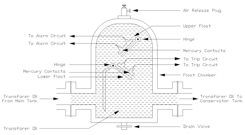
The Buchholz relay consists of the following main components:
1. Float Chamber (Main Body)
The hollow chamber made of non-ferrous metal (typically brass or aluminum) that contains transformer oil. This chamber acts as the monitoring zone where gases are collected and floats are suspended.
2. Upper Float (Light Gas Float)
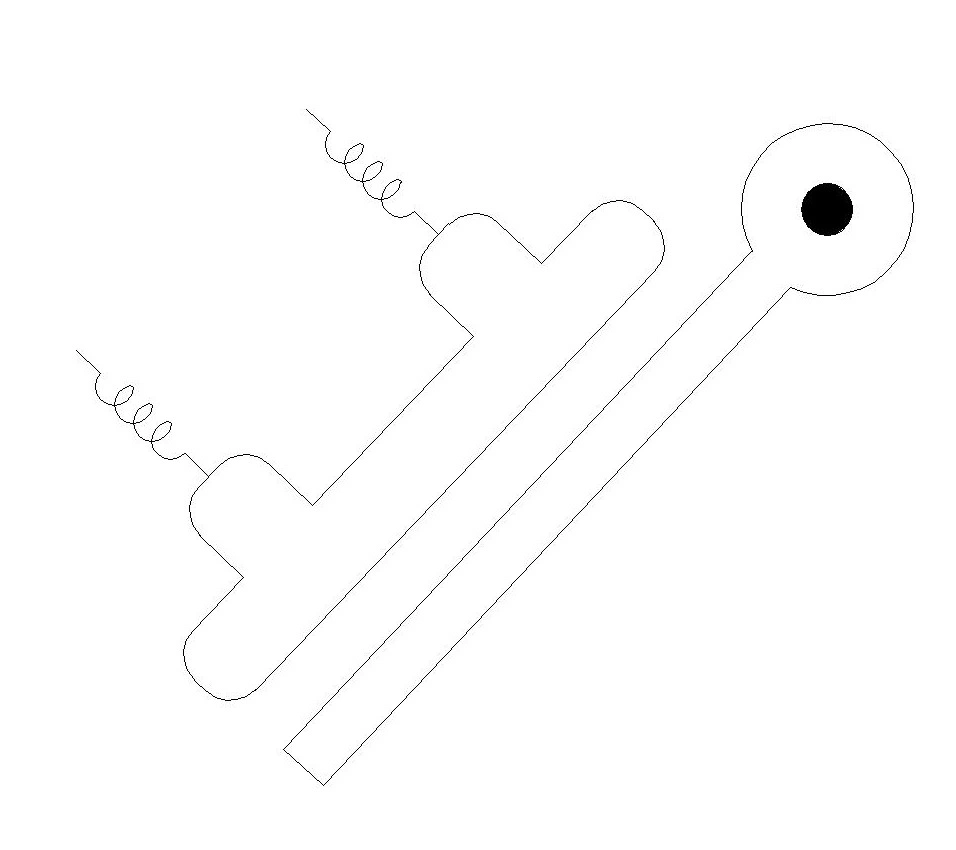
- Located at the top of the chamber
- Floats in transformer oil
- Responds to accumulation of light gases (slow gas generation from incipient faults)
- When gas accumulates in the chamber, the oil level drops and the upper float sinks
- Attached to a mercury contact switch for alarm signal
3. Lower Float (Heavy Gas/Oil Surge Float)
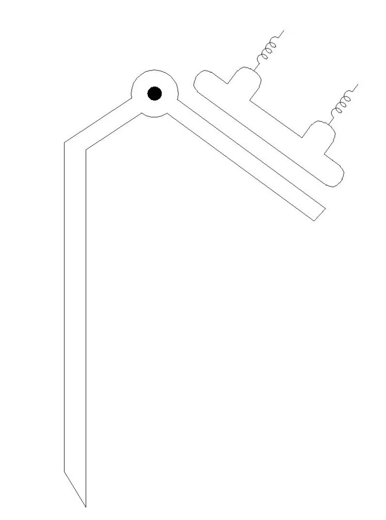
- Located at the bottom/middle of the chamber
- Responds to sudden oil pressure surge (rapid oil movement due to severe faults)
- When oil suddenly flows into the chamber from the main tank at high velocity, this float moves downward
- Attached to a mercury contact switch for trip signal
- More sensitive to the rate of oil flow than to total quantity
4. Mercury Contact Switches (Two sets)
- Alarm contacts (connected to upper float) – closes when upper float sinks
- Trip contacts (connected to lower float) – closes when lower float moves
- Mercury conducts electricity when in contact with the switch terminals
- Provides reliable electrical contact without corrosion
5. Connecting Pipes
- Inlet pipe – from main transformer tank (upper position in relay)
- Outlet pipe – to conservator tank (lower position in relay)
- Allows oil and gas to flow through the relay chamber
6. Drain Plug and Gas Sampling Valve
- Drain plug at bottom for oil drainage and cleaning
- Gas sampling valve at top for gas analysis (dissolved gas analysis – DGA)
- Allows maintenance personnel to collect gas samples for fault diagnosis
How Does Buchholz Relay Work? Operation Principle
The Buchholz relay operates on two distinct principles:
A. Light Gas (Alarm) Operation – Incipient Faults
When minor faults occur inside the transformer (like partial discharge, turn-to-turn short circuits, or core heating), they cause local heating of transformer oil around the fault location.
Step-by-step process:
- Gas Generation: Local heating (around 100-200°C) causes transformer oil insulation to decompose, liberating small quantities of gas (primarily hydrogen – H₂, 70%)
- Gas Collection: Generated gases bubble up and accumulate in the upper portion of the Buchholz relay chamber
- Oil Level Drop: As gas accumulates, it displaces oil from the chamber, causing the oil level to drop
- Upper Float Movement: When oil level drops, the upper float sinks downward following the oil surface
- Mercury Contact Closure: As the upper float descends, it activates a mercury switch which completes an electrical circuit
- Alarm Signal: The closed contact sends an alarm signal to the control room. This triggers:
- Audible alarm (buzzer sound)
- Visual alarm indicator on the control panel
- BUT NO CIRCUIT BREAKER TRIP – the transformer remains connected
Operator Action: The operator receives the alarm signal and can investigate the transformer condition, perform diagnostics, or schedule maintenance without emergency shutdown
B. Heavy Gas (Trip) Operation – Severe Faults
When major internal faults occur (like phase-to-phase short circuits, phase-to-ground faults, or severe arcing), they generate large quantities of gases and cause sudden pressure surges in the transformer oil.
Step-by-step process:
- Severe Fault Occurrence: A serious short circuit or arcing develops inside the transformer, causing very high temperature (above 350°C)
- Rapid Gas & Pressure Generation: The extreme heat causes:
- Massive gas generation (hydrogen, methane, ethane, acetylene)
- Sudden pressure surge in the transformer oil
- Oil Surge (Rapid Flow): The pressure surge forces transformer oil to rapidly flow from the main tank into the conservator tank, passing through the Buchholz relay chamber at high velocity
- Baffle/Vane Deflection (in older designs) or Lower Float Movement (in modern designs):
- Traditional Buchholz: A hinged vane or baffle is pushed by the rapid oil flow
- Modern Buchholz: The lower float is pushed downward by the oil pressure and velocity
- Mercury Contact Closure: The lower float movement activates a second mercury switch which completes a different electrical circuit
- Trip Signal: The closed contact sends a trip signal to the circuit breaker control
- Circuit Breaker Opens: The trip signal commands the circuit breaker to open all phases immediately, isolating the faulty transformer from the power system within milliseconds (typically 50-100 ms)
- Protection Achieved: The faulty transformer is disconnected before:
- Oil temperature reaches the flash point
- Transformer explodes
- Fire spreads to adjacent equipment
- Damage extends to other system components
Practical Examples and Real-World Scenarios
Example 1: Partial Discharge (Incipient Fault)
Situation: A manufacturing defect creates a small void (0.5 mm) in the transformer winding insulation.
What happens:
- Partial discharges occur intermittently during high-voltage stress
- Each discharge generates hydrogen gas (70% composition)
- Gas accumulation: ~0.1 m³ per hour
- Time to Buchholz relay alarm: 2-8 hours
Buchholz Relay Response:
- Upper float sinks as gases accumulate
- Alarm signal triggered
- Plant operators notice the alarm on SCADA
- Technicians conduct DGA (Dissolved Gas Analysis) test
- Results confirm partial discharge (high hydrogen, acetylene ratio)
- Transformer repaired or replaced before catastrophic failure
- No power outage – transformer remains in service until planned maintenance
Example 2: Arcing Fault (Severe Fault)
Situation: Due to inadequate clamping, transformer winding physically moves, causing phase-to-phase contact and arcing.
What happens:
- Arcing generates extremely high temperature (over 1000°C)
- Acetylene (C₂H₂) and hydrogen (H₂) gases produced in massive quantities
- Oil pressure in main tank increases to 3-5 bar
- Oil surge forces through Buchholz relay at velocity > 1 m/s
Buchholz Relay Response:
- Lower float immediately moves due to pressure surge
- Trip signal generated (takes 50 ms)
- Circuit breaker receives trip command
- Circuit breaker opens all three phases (150 kV and 20 kV sides) within 100 ms
- Transformer successfully isolated
- Potential explosion and fire prevented
- Arc burns out within seconds (no more current)
- Power system remains stable – other equipment continues operating
Example 3: Oil Leakage (Incipient Fault)
Situation: Seal deterioration on a pipe connection causes slow oil leak (0.1 L/hour).
What happens:
- Oil level in main tank gradually decreases
- No heat or gas generation from electrical fault
- Oil level in Buchholz relay chamber drops accordingly
Buchholz Relay Response:
- Upper float sinks due to oil level drop (not gas accumulation)
- Alarm signal triggered
- Plant operators are alerted
- Leak location identified and repaired during planned maintenance
- Oil is refilled
- No damage – early detection prevents catastrophic oil loss and transformer overheating
- No automatic trip – transformer operation not interrupted unless oil loss becomes severe
Types of Gases Generated by Different Faults
The gases generated in the transformer oil depend on the type and severity of the internal fault. This relationship is the basis for Dissolved Gas Analysis (DGA) – a technique to diagnose transformer condition:
| Fault Type | Typical Temperature Range | Primary Gases | Gas Percentage | Buchholz Response |
|---|---|---|---|---|
| Partial Discharge | 100-150°C | H₂, C₂H₂ | H₂: 70-80% | Alarm (Light Gas) |
| Turn-to-Turn Short | 200-300°C | H₂, C₂H₄, C₂H₂ | H₂: 60-70% | Alarm (Light Gas) |
| Core Heating | 250-350°C | H₂, CO₂, CO | H₂: 65-75% | Alarm (Light Gas) |
| Oil Oxidation/Aging | 150-200°C | CO, CO₂ | CO₂: dominant | Alarm (Light Gas) |
| Arcing (Phase-to-Phase) | >1000°C | C₂H₂, H₂, C₂H₄ | C₂H₂: 40-50% | Trip (Heavy Gas) |
| Arcing (Phase-to-Ground) | >1000°C | H₂, C₂H₂, C₂H₄ | H₂: 45-55% | Trip (Heavy Gas) |
| Thermal Runaway | >500°C | All types (Multiple) | Variable | Trip (Heavy Gas + Oil Surge) |
Gas Legend:
- H₂ = Hydrogen gas (most common, 70% of all generated gases)
- CH₄ = Methane gas
- C₂H₂ = Acetylene gas (indicator of high-temperature arcing)
- C₂H₄ = Ethylene gas
- CO = Carbon monoxide
- CO₂ = Carbon dioxide
Buchholz Relay Alarm vs. Trip – Key Differences
| Feature | Alarm Signal | Trip Signal |
|---|---|---|
| Trigger | Accumulation of light gases | Rapid oil pressure surge + heavy gases |
| Response Time | Slow (minutes to hours) | Fast (50-100 milliseconds) |
| Float Activated | Upper float | Lower float |
| Gas Volume Required | 0.2-0.5 m³ accumulation | Any rapid surge (instantaneous) |
| Circuit Breaker Action | DOES NOT OPEN | OPENS IMMEDIATELY |
| Plant Operations | Transformer remains in service | Transformer disconnected |
| Fault Type | Incipient (developing) faults | Severe (catastrophic) faults |
| Operator Action | Investigate, plan maintenance | Emergency response |
| Typical Faults | Partial discharge, winding shorts, oil leakage | Phase-to-phase short, arcing, thermal runaway |
Advantages and Limitations of Buchholz Relay
Advantages:
✅ Early Fault Detection – Detects incipient faults before they develop into severe faults
✅ High Sensitivity – Can detect faults with very small current levels
✅ Mechanical Simplicity – No complex electronics, highly reliable
✅ Low Maintenance – Requires no regular servicing during normal operation
✅ Cost-Effective – Inexpensive compared to other protection devices
✅ No False Alarms from External Faults – Only responds to internal transformer conditions
✅ Fast Response to Severe Faults – Trip action within 100 ms
✅ Diagnostic Information – Collected gases can be analyzed (DGA) for fault type identification
Limitations:
❌ Slow Alarm Response – Light gas accumulation may take hours to trigger alarm
❌ Sensitive to Oil Movement – Vibration or thermal expansion can cause false alarms
❌ Limited Fault Discrimination – Cannot distinguish between different incipient fault types
❌ Maintenance Required – Mercury needs occasional checking (though rare)
❌ Cannot Detect Electrical Faults Outside Tank – Only protects internal faults
❌ Requires Conservator Tank – Not applicable to sealed transformers or dry-type transformers
❌ Drain Plug Maintenance – Requires periodic draining and cleaning to remove accumulated sediment
Buchholz Relay Settings and Calibration
The Buchholz relay must be properly calibrated to ensure reliable operation. Settings are typically established during manufacturing but must be verified during installation and periodically during maintenance.
Alarm Setting (Light Gas):
- Standard Gas Accumulation: 0.2 – 0.5 m³ (depending on relay size)
- Response Time: 1-8 hours after fault begins
- Typical Threshold: When oil level drops to activate upper float
Trip Setting (Heavy Gas):
- Oil Flow Velocity Threshold: 0.8 – 1.5 m/s (modern relays)
- Response Time: 50-100 milliseconds
- Typical Threshold: When lower float moves beyond 3-5 mm displacement
Testing and Verification:
- Gas Injection Test – Air is carefully injected through the gas sampling valve to simulate gas accumulation and verify alarm operation
- Oil Flow Test – Oil is manually pushed through the relay to verify trip operation
- Visual Inspection – Mercury contact condition, float movement, and oil level are checked
- Electrical Testing – Alarm and trip contacts are tested with ohmmeter to ensure continuity
Buchholz Relay Maintenance Procedure
Annual Maintenance:
- Visual inspection of relay body for corrosion or damage
- Check oil level in relay chamber
- Verify alarm and trip contacts respond to manual push-button test
- Inspect inlet and outlet pipes for blockage
- Verify proper gas flow through sampling valve
Three-Year Maintenance:
- Drain transformer oil from relay chamber
- Clean chamber interior with filtered transformer oil
- Inspect floats for corrosion, sticking, or damage
- Check mercury contact condition and re-amalgam if necessary
- Refill chamber with fresh transformer oil (same grade as in tank)
- Perform gas injection test and oil flow test
- Verify alarm and trip settings
Five-Year Maintenance:
- Complete replacement of relay if available spare is in stock
- Alternatively, complete disassembly, cleaning, and reassembly
- Factory calibration and testing
- Documentation of all findings
Modern Advances in Buchholz Relay Technology
Recent developments have improved the reliability and functionality of Buchholz relays:
Improved Float Design:
- Ball float design – spherical floats with improved stability and less sticking
- Double float configuration – separate floats for alarm and trip with independent movement
Enhanced Sensitivity:
- Baffle angle monitoring – Hall sensors detect baffle rotation before mercury contact closure
- Pressure wave detection – enhanced ability to detect incipient fault pressure waves
Wireless Monitoring:
- Real-time gas concentration monitoring using capacitive sensors
- Wireless transmission of relay status and gas levels to SCADA
- Remote troubleshooting and diagnosis capabilities
- Alert generation before alarm threshold is reached
Integrated Protection:
- Combined gas relay and oil pressure relief in single unit
- Integration with differential protection and other relay functions
- Advanced diagnostics using dissolved gas analysis (DGA) data
Conclusion
The Buchholz relay remains one of the most valuable and cost-effective protective devices for oil-immersed power transformers. Its ability to detect incipient faults at early stages, combined with its mechanical simplicity and high reliability, makes it an indispensable component of transformer protection systems worldwide.
Understanding the working principle, construction, and operation of the Buchholz relay is essential for electrical engineers, technicians, and plant operators involved in transformer maintenance and protection. The distinction between light gas (alarm) and heavy gas (trip) responses allows power systems to balance protection sensitivity with operational continuity.