Every electrical installation depends on a properly functioning earthing system to protect human life and equipment from fault currents. A copper plate buried in the ground or a rod driven into soil means nothing if the resistance between that electrode and the earth is too high. The only way to confirm that your grounding system will actually perform during a fault is to measure the earth pit resistance accurately using proven testing methods.
The Earth Pit Resistance Measurement Test is the standard field procedure used to verify the effectiveness of any grounding electrode. This test determines if the earth electrode can dissipate fault currents safely and within the limits set by national and international standards.
In this technical guide, we will discuss everything you need to know about earth pit resistance measurement testing, including the working principle of earth testers, the standard three-point fall of potential method, the 62% rule, verification procedures, spike placement, acceptable resistance limits, alternative testing methods, and relevant industry standards. Practical examples are included throughout to help you apply these concepts in real-world scenarios confidently.
1. What is Earth Pit Resistance?
Earth pit resistance is the electrical resistance measured between an earth electrode and the surrounding soil. This parameter is important because it directly affects how effectively a grounding system can dissipate fault currents. A fault in an electrical installation forces current to flow through the earth electrode into the soil. If the resistance is too high, dangerous voltage rises occur on exposed metalwork, creating electric shock hazards and equipment damage. Regular earth pit resistance testing is therefore a mandatory requirement in electrical installations, as specified by international standards including IEEE 81, IEC 60364, IS 3043, and ANSI/NFPA 70 (National Electrical Code).
To visualize earth resistance, think of your electrical system as a house with a plumbing system. The fault current is unwanted waste water, and the earth pit acts like the main drain pipe leading this water out into the municipal sewer. If the drain pipe is wide and clean (low resistance), any sudden rush of water flushes away instantly, keeping your house safe. But if the drain pipe is clogged or too narrow (high resistance), the water backs up and causes damage.
Similarly, if your earth pit resistance is high, dangerous fault current cannot escape into the ground quickly. It stays on the metal bodies of your equipment such as transformer tanks or motor casings. If a person touches this equipment, the current flows through their body instead of the ground. This can lead to a fatal electric shock.
2. How the Earth Tester Works
An earth tester is a specialized instrument designed to measure the resistance between an earth electrode and the surrounding soil using non-destructive testing methods. This instrument is sometimes called a ground resistance tester or earth megger in field terminology.
The hand-operated earth tester uses a hand-crank driven DC generator as its power source. The operator rotates the generator handle, which drives the electrical components inside. The tester incorporates two components: a current reverser and a rectifier, both mounted on the generator shaft. These components work together to convert the DC output into alternating current (AC) for injection into the earth. The received AC signal is then converted back to DC for display on the instrument scale.
3. Why AC Current is Used Instead of DC
The generator produces DC, but earth testers use AC current for actual soil injection through the current reverser. The reason is straightforward. A prolonged DC current causes electrolytic effects similar to water electrolysis. The DC gradually creates bubbles of hydrogen and oxygen around the electrodes. These bubbles form a gaseous barrier that blocks current flow and produces unreliable measurements. Using AC current eliminates this electrolytic effect and produces accurate, repeatable results.
The frequency of the AC signal is selected to avoid commercial power frequencies (50 Hz or 60 Hz). This reduces interference from nearby electrical installations. Most earth testers operate at frequencies like 128 Hz, 111 Hz, or 105 Hz. Some older models use 16 Hz or 400 Hz. The chosen test frequency must not be a harmonic of the local power frequency to prevent stray current errors, as noted in IEEE 81-2012 (now updated to IEEE 81-2025).
4. Internal Working Principle
Inside the tester, there is one current coil and one pressure (potential) coil. The current coil measures the actual current flowing through the soil between the test electrodes. The potential coil measures the voltage drop between the earth electrode under test and the potential measuring electrode. The pointer movement is proportional to the ratio of voltage to current, following Ohm’s Law (R = V/I). The resistance value is displayed directly on a calibrated scale in Ohms (Ω).
5. Measurement of Earth Resistance — Three Point Fall of Potential Method
The most reliable and widely accepted method for measuring earth pit resistance is the Three Point Method, also called the Fall of Potential Method. This method is recommended by IEEE 81, IS 3043, BS 7430, and ANSI/NFPA 70. It involves the earth electrode under test and two auxiliary spikes driven into the ground.
5.1 Pre-Test Preparations
Before starting the test, note the following preparatory steps:
Weather and Timing: Perform the test during the driest period of the year. This gives you the worst-case (highest) resistance reading. Avoid testing immediately after rain because wet soil gives falsely low readings. Never test during lightning or thunderstorm activity. Record the weather conditions and soil state in your test report for future reference.
Stray Voltage Check: Before connecting the earth tester, use a voltmeter to measure the voltage between the earth electrode and the ground near the auxiliary spike locations. If a notable stray voltage exists (from nearby ground faults, induced voltages, or energized systems), the test readings may be unreliable or testing may be hazardous. Many modern digital earth testers measure stray voltage automatically and display a warning.
Lead Inspection: Check all test leads for continuity and insulation integrity before use. Damaged leads introduce errors and create safety hazards.
5.2 Step 1: Isolation of the Earth Electrode
Before starting the measurement, disconnect the earth electrode from the main earthing grid or the equipment it protects. If you measure with the electrode still connected, your reading will include the parallel resistance of the entire grid. This gives a falsely low value that does not represent the individual electrode’s performance. The earth electrode under test must be completely isolated.
5.3 Step 2: Understanding the Terminals
Earth testers come with either three terminals or four terminals, depending on the model.
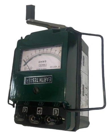
3-Terminal Earth Testers (common in older analog models like the one shown in the image below) label the terminals as E (Earth), P (Potential), and C (Current).
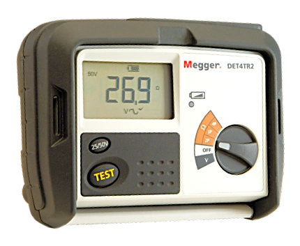
4-Terminal Earth Testers (common in modern digital models) label the terminals as C1, P1, P2, and C2.
The equivalence between the two naming systems is:
| 4-Terminal System | 3-Terminal System | Connection |
|---|---|---|
| C1 + P1 (shorted together) | E | Earth electrode under test |
| P2 | P | Potential spike (inner auxiliary electrode) |
| C2 | C | Current spike (outer auxiliary electrode) |
5.3.1 3-Terminal vs. 4-Terminal Configuration:
In the 3-terminal configuration, you short C1 and P1 together with a jumper wire and connect them to the earth electrode using a single lead. This is simple and works well for most measurements above 2Ω.
In the 4-terminal configuration, C1 and P1 are connected to the earth electrode using two separate leads. This eliminates the test lead resistance from the measurement. For low-resistance measurements (below 1–2Ω), such as at large power stations and major substations, always use the 4-terminal configuration. If you use the 3-terminal method for a 0.5Ω earth pit and your test leads have 0.1Ω resistance each, you will read 0.7Ω instead of 0.5Ω, a 40% error.
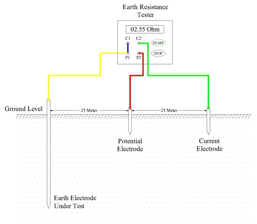
5.4 Step 3: Connections and Spike Placement
Connect the earth tester as follows:
- Connect C1 and P1 (shorted together for 3-terminal method, or separately for 4-terminal method) to the earth electrode under test.
- Drive the first auxiliary spike (the Potential Spike) into the ground and connect it to terminal P2.
- Drive the second auxiliary spike (the Current Spike) into the ground and connect it to terminal C2.
5.4.1 Auxiliary Spike Installation:
Drive each auxiliary spike at least 300 mm to 500 mm (roughly 12 to 20 inches) into the ground. The spike must make firm contact with the soil. If the ground is very dry, hard, or rocky, pour some water around the spike location to improve contact. If the auxiliary spike resistance is too high, the tester may not inject enough current into the soil and the reading will be unreliable. Many modern digital testers display a warning when auxiliary electrode contact resistance is excessive.
5.4.2 Lead Routing
Keep the three test leads separated from each other along their entire run. Do not bundle them together. Avoid running leads parallel to power cables, metallic fences, pipelines, or other grounded structures. Electromagnetic coupling between leads or between leads and nearby conductors introduces measurement errors.
5.5 Step 4: Distance, Alignment, and the 62% Rule
The placement of auxiliary spikes is the single most important factor in getting an accurate reading. All three points (the earth electrode, the potential spike, and the current spike) must be placed in a straight line.
5.5.1 The 62% Rule:
The standard Fall of Potential method is based on a mathematical principle. For a hemispherical electrode model, the true earth resistance reading occurs when the potential spike (P2) is placed at 62% of the distance between the earth electrode and the current spike (C2). This is called the 62% rule.
Example Calculation:
If you place the current spike (C2) at 50 meters from the earth electrode:
- P2 position = 62% × 50 m = 31 meters from the earth electrode.
If you place C2 at 30 meters:
- P2 position = 62% × 30 m = 18.6 meters from the earth electrode.
5.5.2 How Far Should C2 Be?
For a small individual earth pit (single rod or plate), placing C2 at 30 to 50 meters is generally sufficient.
For a large grounding grid (such as at a substation), IEEE 81 recommends placing C2 at a distance of at least 5 to 10 times the maximum diagonal dimension of the grid. For example, if a substation grounding grid measures 40m × 40m (diagonal ≈ 57m), the current spike should be placed at least 285m to 570m away. This makes the zones of influence well separated and produces an accurate reading.
5.6 Step 5: Taking the Reading
Once all connections are made and spikes are positioned correctly, take the measurement:
- For analog hand-crank testers, rotate the generator handle at a steady speed, usually around 135 to 160 RPM depending on the model. The pointer will settle on the resistance value in Ohms (Ω).
- For digital earth testers, press the “Test” button. The instrument will inject the test current automatically and display the reading on screen.
5.7 Step 6: Verification
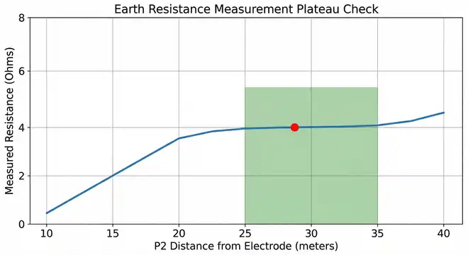
A single reading is not enough to confirm accuracy. You must verify that you are measuring at the correct point by performing a plateau check (also called a resistance profile check).
Here is how to do it:
- Keep the current spike (C2) at its fixed position (for example, 50 meters).
- Take readings with the potential spike (P2) at multiple positions between the earth electrode and C2. Move P2 to approximately 50%, 55%, 60%, 62%, 65%, 70%, and 75% of the C2 distance.
For a C2 distance of 50 meters, these P2 positions would be:
| P2 Position (% of C2) | P2 Distance from Electrode |
|---|---|
| 50% | 25.0 m |
| 55% | 27.5 m |
| 60% | 30.0 m |
| 62% | 31.0 m |
| 65% | 32.5 m |
| 70% | 35.0 m |
| 75% | 37.5 m |
- Plot the readings on a graph (Resistance vs. P2 Distance).
- Look for a flat region (plateau) on the graph. If the readings between 55% and 70% are within ±5% of each other, the reading at the 62% point is your true earth resistance.
- If the graph shows a continuously rising curve with no flat portion, the current spike is not far enough away. Move C2 further (for example, to 70m or 100m) and repeat the entire series.
Example: You get readings of 3.8Ω at 50%, 4.0Ω at 55%, 4.1Ω at 60%, 4.1Ω at 62%, 4.2Ω at 65%, 4.1Ω at 70%, and 4.3Ω at 75%. The readings between 55% and 70% are all within ±5% of 4.1Ω. This confirms that 4.1Ω is the true earth pit resistance.
This verification step separates a professional-grade measurement from a rough field estimate.
6. Acceptable Limits for Earth Resistance
After you get the value, you need to determine if it meets the required standard. The acceptable limit depends on the type of installation. General safety standards like IS 3043, IEEE 80, and ANSI/NFPA 70 provide the following benchmarks:
| Installation Type | Acceptable Resistance Value |
|---|---|
| Large Power Stations (with Grid) | ≤ 0.5 Ω to 1.0 Ω |
| Major Substations | ≤ 1.0 Ω |
| Small Substation / Industrial Plant | ≤ 2.0 Ω |
| Domestic / Ordinary Earth Pit | ≤ 5.0 Ω (standard) / ≤ 10 Ω (acceptable without grid) |
| Transmission Tower Footing | ≤ 10 Ω |
| Lightning Protection System | ≤ 10 Ω (per NFPA 780 / IEC 62305) |
A value of 1Ω or less is ideal for systems connected to a grounding grid. For isolated pits without a grid, values up to 10Ω are often considered the upper limit of acceptability. Lower is always safer.
7. Test Report Format
A proper test report should include the following information: date and time of test, instrument make and model with calibration date, earth electrode identification number, electrode type (rod/plate/pipe), electrode location, test method used, C2 and P2 distances, all measured resistance values (including plateau check readings), soil condition (dry/moist/wet), ambient temperature, weather conditions, and the name and signature of the testing engineer.
8. What to Do If the Reading Exceeds Acceptable Limits
If your measured earth pit resistance is above the acceptable limit, do not simply accept it and move on. Several corrective measures can bring the value within limits:
1. Watering the Earth Pit: Pouring water (preferably mixed with common salt) around the earth electrode temporarily lowers soil resistivity. This is a short-term fix and the resistance will rise again as the soil dries out.
2. Adding Charcoal and Salt Layers: Surrounding the electrode with alternate layers of charcoal and salt improves moisture retention and soil conductivity. This is a traditional method specified in IS 3043.
3. Using Chemical Earthing Compounds: Modern earth enhancement materials like bentonite, marconite, or proprietary chemical earth rods are highly effective. These compounds absorb and retain moisture, maintaining low resistivity over long periods. Chemical earthing compound solutions are widely used in commercial and industrial electrical grounding systems.
4. Installing Additional Parallel Earth Pits: If a single earth pit cannot achieve the required resistance, install additional pits and connect them in parallel. The combined resistance of N identical pits in parallel is approximately R/N. For example, if one pit measures 8Ω, two identical pits in parallel give approximately 4Ω, and four pits give approximately 2Ω.
5. Increasing Electrode Depth: Driving the electrode deeper reaches soil layers with higher moisture content and lower resistivity. This is especially effective in areas where the water table is relatively shallow.
After implementing any corrective measure, re-test the earth pit to confirm that the resistance now meets the required limit.
9. Alternative Testing Methods for Earth Pit Resistance
The three-point fall of potential method remains the gold standard for earth pit resistance measurement. However, several alternative methods exist for situations where the standard method is impractical.
9.1 Selective Testing Method
The selective testing method is used for testing individual earth electrodes within interconnected grounding systems where complete disconnection is not practical. This method uses a current clamp placed around the conductor under test without disconnecting it from the system. The clamp meter injects a known AC test signal into the electrode. Two conventional auxiliary electrodes (stakes) are positioned at appropriate distances, one for the potential reference and one at remote distance. This method is useful in industrial facilities with complex grounding networks where isolating a single electrode would require extensive shutdowns.
9.2 Wenner Four-Point Method
The Wenner four-point method is primarily used for measuring soil resistivity rather than individual earth electrode resistance. It is most commonly used during the design phase of grounding systems to characterize the soil at a proposed site.
Four small electrodes of equal size are driven into the soil at the same depth in a straight line with equal spacing between them. Current is injected between the outer two electrodes, and voltage is measured between the inner two. This arrangement measures voltage in the region of the most uniform electric field, producing reliable and repeatable results.
Measurements are taken at multiple electrode spacings, from 0.5 meters to 10 meters or more. Each measurement gives the average soil resistivity at a depth approximately equal to the electrode spacing. Repeating measurements at increasing spacings builds a profile of soil resistivity versus depth. Engineers use this profile to determine the optimal earth electrode depth and type for the installation. The Wenner method is more labor-intensive than the fall of potential method but provides valuable site characterization data that directly influences grounding system design and earth pit installation cost.
9.3 Clamp-On Method (Stakeless Testing)
The clamp-on method eliminates the need to drive auxiliary electrodes into the ground. This is a major advantage in urban areas, locations with concrete-covered ground, hard rocky soil, or sites where ground disturbance is not permitted.
The operator uses a specialized clamp-on earth resistance meter that clamps around the grounding conductor without breaking the circuit. The meter injects an AC test signal and measures the current flowing in the grounding loop. Resistance is calculated using Ohm’s Law.
The main limitation of clamp-on testing is that it measures the resistance of the entire parallel path through which current can return, not just the individual electrode under test. In installations with multiple grounding paths (water pipes, structural steel, multiple electrodes), the meter reads the combined resistance of all parallel paths. This often results in readings lower than the actual individual earth pit resistance. Therefore, clamp-on results should be treated as screening measurements rather than precise earth pit resistance values. The method is most accurate for simple installations with limited parallel return paths.
10. Why Do Earth Resistance Values Vary?
You might measure an earth pit today and get 2.5Ω, and measure the same pit three months later in summer and get 8.0Ω. This variation happens because earth resistance depends heavily on the resistivity of the surrounding soil.
Moisture content is the single biggest factor. Dry soil acts like an insulator. Moist soil contains dissolved salts that create a conductive electrolyte, allowing current to flow more easily. This is why earth pits are often watered with saline solution before testing or during dry seasons.
Temperature also plays a role. Frozen ground has extremely high resistance. Warm soil conducts better. Soil composition matters too. Rocky or sandy soil drains water quickly but has poor electrical conductivity. Clay or loamy soil retains moisture and offers much lower resistance.
Because of these variables, the best practice is to test earth pits during the driest and hottest period of the year. This gives the worst-case reading. If the earth pit passes the test under these conditions, it will perform even better during wetter seasons.
11. Standards and Regulations Governing Earth Pit Testing
Several international and national standards specify procedures and requirements for earth pit resistance measurement and grounding system testing.
11.1 IEEE Standard 81-2012 (updated to IEEE 81-2025)
This is the primary guide for measuring earth resistivity, ground impedance, and earth surface potentials of grounding systems. The standard covers multiple testing methods including the fall of potential method, two-point method, four-point method, clamp-on method, and slope method.
IEEE 81 provides detailed guidance on the 62% rule, sources of measurement error, lead routing, and safety considerations. The standard acknowledges that extreme precision is rarely achievable due to soil variability and recommends that measurements be performed carefully using the most suitable method with a thorough awareness of error sources.
11.2 IEEE Standard 80 (IEEE Guide for Safety in AC Substation Grounding)
IEEE Standard 80 provides design criteria for grounding systems including maximum allowable step and touch voltages. Earth pit resistance measurements support verification of IEEE 80 design calculations.
11.3 ANSI/NFPA 70 (National Electrical Code – NEC)
ANSI/NFPA 70, Article 250 covers grounding and bonding requirements for electrical installations in the United States. Section 250.53 specifies electrode installation requirements, and Section 250.56 states that if a single rod, pipe, or plate electrode has a resistance to earth greater than 25 ohms, it must be supplemented by an additional electrode. The NEC is the primary electrical safety code referenced across North America.
11.4 IEC 60364-5-54 and IEC 60364-6
These standards cover earthing requirements for low-voltage electrical installations internationally. These standards require that earth electrodes achieve the resistance value needed for protective device coordination and mandate periodic testing.
11.5 IS 3043:2018
IS 3043:2018 is the Indian Standard Code of Practice for Earthing. Clause 27 establishes earth resistance requirements. The standard specifies that the continuity resistance of the earth return path through the earth grid should be maintained as low as possible and in no case greater than 1 ohm for main earthing conductors.
11.6 BS 7430:199
BS 7430:199 is the British Standard Code of Practice for Earthing, providing design and testing guidance for the United Kingdom and commonwealth countries.
12. Conclusion
Earth pit resistance measurement is a mandatory testing procedure that confirms the effectiveness of any grounding system. The three-point fall of potential method, performed according to IEEE 81 and IS 3043, provides accurate and reliable results when executed properly. The two most important aspects of this test are correct spike placement using the 62% rule and verification of results through the plateau check. A single reading at an arbitrary distance is not sufficient for professional-grade work.
Always test during the driest season for worst-case results, use the 4-terminal configuration for low-resistance measurements, and reconnect the electrode immediately after testing. If the measured resistance exceeds the acceptable limit, implement corrective measures and re-test until compliance is achieved.
13. Frequently Asked Questions (FAQs)
For a domestic or ordinary earth pit, the acceptable resistance is 5Ω or less as per IS 3043. Without a connected grounding grid, values up to 10Ω are sometimes accepted, but lower values are always preferred for safety.
Earth pit resistance should be tested at least once every year. For industrial and high-voltage installations, testing every six months is recommended.
The 62% rule states that the potential spike (P2) should be placed at 62% of the distance between the earth electrode and the current spike (C2). For example, if C2 is at 50 meters, P2 should be at 31 meters.
The standard fall of potential method requires the electrode to be isolated from the grounding system. If disconnection is not possible, the selective testing method or clamp-on method can be used.
Earth resistance depends heavily on soil moisture content. During dry seasons, the soil loses moisture and becomes more resistive. During wet seasons, dissolved salts in moist soil create a conductive path and resistance drops.
A 3-terminal tester shorts the current injection and potential sensing terminals (C1 and P1) together at the instrument, using one lead to the electrode. A 4-terminal tester uses separate leads for C1 and P1 to the electrode, eliminating lead wire resistance from the measurement. The 4-terminal method is more accurate for low-resistance measurements below 1–2Ω.
You can lower earth pit resistance by watering the pit with saline solution, adding charcoal and salt layers, using chemical earthing compounds like bentonite or marconite, installing additional parallel earth pits, or driving the electrode deeper into the ground.
Earth testers use AC frequencies that are different from the local power frequency (50 Hz or 60 Hz) to avoid interference. Common test frequencies include 105 Hz, 111 Hz, 128 Hz, or 400 Hz.