Every electrical system needs a stable voltage supply to function properly. Voltage fluctuations are a common challenge in power systems, and they can damage equipment, reduce efficiency, and cause unexpected shutdowns. An Automatic Voltage Regulator (AVR) is a device designed to maintain a constant voltage level without any manual intervention. It continuously monitors the output voltage and makes real-time adjustments to keep it within an acceptable range.
AVRs are used across a wide range of applications. You will find them in power generation plants, industrial facilities, commercial buildings, and residential backup systems. They play a direct role in protecting sensitive electrical equipment such as motors, transformers, computers, and medical devices from the harmful effects of overvoltage and undervoltage conditions.
In this technical guide, we will discuss everything you need to know about Automatic Voltage Regulators, including their working principle, types, applications, relay settings, coordination strategies, testing methods, and relevant industry standards. Practical examples are included throughout to help you apply these concepts in real-world scenarios confidently.
1. What is an Automatic Voltage Regulator (AVR)?
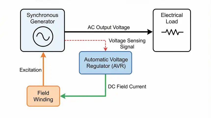
An Automatic Voltage Regulator is an electronic or electromechanical device that maintains a steady output voltage from a power source. It does this by automatically adjusting the excitation current in generators or by regulating the tap positions in transformers. The main goal is to keep the terminal voltage constant regardless of changes in load or input conditions.
In a generator system, the AVR senses the output voltage through a voltage sensing circuit. If the voltage drops below the set point, the AVR increases the excitation current to the generator’s field winding. If the voltage rises above the set point, the AVR reduces the excitation current. This closed-loop feedback mechanism allows the system to maintain voltage stability at all times.
For example, consider a diesel generator rated at 500 kVA supplying power to a hospital. The load on this generator changes constantly as different departments switch equipment on and off. Without an AVR, the voltage at the generator terminals would fluctuate with every load change. The AVR detects these fluctuations and adjusts the field excitation within milliseconds. This keeps the voltage stable at, say, 415V ± 1%, which is within the acceptable tolerance for most hospital equipment.
2. Why Do We Need Automatic Voltage Regulators?
Voltage stability is not just a matter of convenience. It is a matter of safety and operational reliability. Here are the main reasons why AVRs are needed in electrical systems.
Equipment Protection: Most electrical equipment is designed to operate within a specific voltage range. Motors, for instance, can overheat and suffer insulation damage if operated at voltages more than 10% above or below their rated value. An AVR prevents this by holding the voltage within safe limits.
Power Quality Improvement: Industrial facilities often deal with power quality issues such as voltage sags, swells, and flicker. These problems can cause production losses, data corruption, and premature equipment failure. An AVR installed at the point of common coupling or at the generator output improves power quality for the entire facility.
Reactive Power Management: In synchronous generators, the AVR controls the field excitation, which directly affects the reactive power output. Proper reactive power management helps maintain voltage profiles across the power system and reduces transmission losses.
System Stability: In interconnected power systems, voltage instability can lead to cascading failures and blackouts. AVRs on generators help maintain system voltage within acceptable limits and contribute to overall grid stability.
Practical Example: A manufacturing plant with CNC machines requires a voltage stability of ±2%. The incoming supply from the utility varies between 390V and 440V during peak and off-peak hours. Installing a servo-controlled AVR at the main distribution board brings the voltage to a stable 415V ±1%. This eliminates random CNC errors and reduces downtime.
3. Working Principle of an Automatic Voltage Regulator
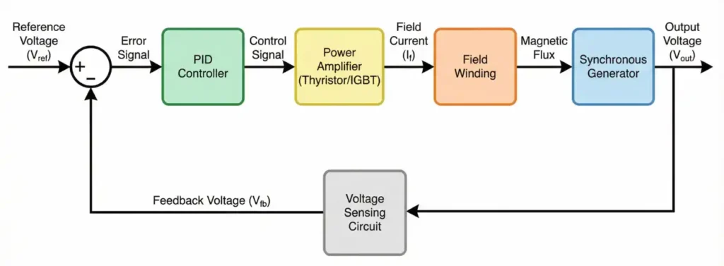
The working principle of an AVR is based on the concept of closed-loop feedback control. The system continuously compares the actual output voltage with a reference voltage and generates an error signal. This error signal drives the control circuit to adjust the excitation current or transformer tap position until the output voltage matches the reference.
Here is a step-by-step breakdown of how a generator AVR works:
Step 1: Voltage Sensing
The AVR has a voltage sensing circuit that measures the generator’s output voltage. This is usually done through a potential transformer (PT) that steps down the output voltage to a level suitable for the control electronics.
Step 2: Comparison
The sensed voltage is compared with a preset reference voltage inside the AVR. The reference voltage is adjustable and is set during commissioning based on the generator’s rated voltage.
Step 3: Error Detection
If there is a difference between the sensed voltage and the reference voltage, an error signal is generated. A positive error means the voltage is too high. A negative error means the voltage is too low.
Step 4: Signal Processing
The error signal passes through a controller, which is often a PID (Proportional-Integral-Derivative) controller. The controller calculates the appropriate corrective action based on the magnitude and duration of the error.
Step 5: Power Amplification
The controller output drives a power amplifier stage, which adjusts the current flowing through the generator’s field winding. In modern AVRs, this is done using thyristors or IGBTs (Insulated Gate Bipolar Transistors).
Step 6: Correction
The change in field current changes the magnetic flux in the generator. This directly affects the induced EMF and, therefore, the output voltage. The voltage returns to the set point.
Step 7: Continuous Monitoring
This entire process repeats continuously in real time. The response time of modern digital AVRs is in the range of 20 to 50 milliseconds.
4. Types of Automatic Voltage Regulators
AVRs come in different designs based on the application, power rating, and method of voltage regulation. Here are the most common types used in the industry.
4.1 Electromechanical AVR (Servo-Controlled)
This type uses a servo motor to adjust the position of a variable transformer (variac). The servo motor moves the wiper of the variac to increase or decrease the output voltage. These regulators are commonly used in commercial and light industrial applications.
Advantages: Simple design, easy to maintain, and can handle large voltage correction ranges (up to ±30%).
Disadvantages: Slow response time (typically 1-3 seconds for full correction), mechanical wear over time, and not suitable for applications requiring fast voltage regulation.
Example: A servo-controlled AVR rated at 100 kVA is installed in an office building to regulate the incoming utility supply from a range of 360V–460V down to a stable 400V ±1%.
4.2 Static AVR (Solid-State)
Static AVRs use semiconductor devices like thyristors (SCRs), TRIACs, or IGBTs to regulate voltage. They have no moving parts, which makes them faster and more reliable than electromechanical types.
Advantages: Fast response time (less than 100 milliseconds), long operational life, compact size, and high accuracy.
Disadvantages: More expensive than electromechanical types, can introduce harmonic distortion if not properly filtered, and require skilled personnel for installation and maintenance.
Example: A static AVR is used in a data center to maintain the UPS input voltage at 415V ±0.5%. The fast response of the static AVR prevents voltage transients from reaching the UPS, which extends the battery life and improves overall system reliability.
4.3 Digital AVR
Digital AVRs use microprocessors or DSP (Digital Signal Processor) chips to control the voltage regulation process. They offer programmable settings, built-in protection features, communication interfaces (Modbus, PROFIBUS, Ethernet), and data logging capabilities.
Advantages: High precision, programmable parameters, remote monitoring capability, self-diagnostics, and integration with SCADA systems.
Disadvantages: Higher cost, requires trained personnel for programming and commissioning, and can be sensitive to electromagnetic interference if not properly shielded.
Example: A 200 MW thermal power plant uses digital AVRs on its synchronous generators. The AVRs are connected to the plant’s DCS (Distributed Control System) through Modbus communication. Operators can monitor and adjust the voltage set point, droop settings, and protection parameters from the control room.
4.4 Magnetic AVR (Saturable Reactor Type)
This older type uses a saturable reactor (magnetic amplifier) to control the output voltage. The reactor’s impedance changes based on a DC control current, which in turn adjusts the AC output voltage.
Advantages: No moving parts, robust construction, and suitable for harsh environments.
Disadvantages: Bulky, slower response compared to static AVRs, and less accurate.
These regulators have been largely replaced by static and digital AVRs in modern installations. However, they are still found in some legacy systems.
5. Components of an AVR System
A typical AVR system consists of several interconnected components. Each component has a specific function in the voltage regulation process.
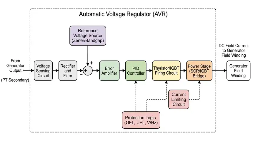
5.1 Voltage Sensing Circuit
This circuit measures the generator or transformer output voltage. It usually includes a potential transformer (PT) and a rectifier to convert the AC voltage into a DC signal for processing.
5.2 Reference Voltage Source
A stable reference voltage is generated internally using a precision voltage reference IC (such as a Zener diode-based circuit or a bandgap reference). This serves as the benchmark for comparison.
5.3 Error Amplifier
This component amplifies the difference between the sensed voltage and the reference voltage. The output of the error amplifier drives the controller.
5.4 PID Controller
The PID controller processes the error signal and generates a control output. The proportional gain determines the immediate response. The integral gain eliminates steady-state errors. The derivative gain improves transient response and reduces overshoot.
5.5 Thyristor/IGBT Firing Circuit
In static and digital AVRs, this circuit generates the firing pulses for the power semiconductors. The firing angle of the thyristors determines the amount of current flowing through the generator’s field winding.
5.6 Field Winding
The field winding of the synchronous generator produces the magnetic field required for power generation. The AVR controls the DC current flowing through this winding.
5.7 Current Limiting Circuit
This circuit limits the field current to a safe value during fault conditions or sudden load changes. It prevents damage to the field winding and the excitation system.
5.8 Protection Features
Modern AVRs include built-in protections such as overvoltage, undervoltage, overexcitation, underexcitation, V/Hz limiter, and loss of sensing protection.
6. AVR in Synchronous Generators
Synchronous generators are the workhorses of the power generation industry. Every synchronous generator requires an excitation system, and the AVR is the brain of this system.
The excitation system supplies DC current to the rotor field winding. This current creates a magnetic field that rotates with the rotor. As the magnetic field cuts across the stator windings, an AC voltage is induced. The magnitude of this voltage depends directly on the strength of the magnetic field, which in turn depends on the field current.
The AVR controls this field current to maintain the desired output voltage. Here is how it works in practice.
No-Load Operation: The generator is running at rated speed but not connected to any load. The AVR adjusts the field current to produce the rated terminal voltage. For a generator rated at 11 kV, the AVR sets the field current such that the open-circuit voltage is exactly 11 kV.
Load Applied: A load is connected to the generator. The load draws current from the stator, which creates its own magnetic field (armature reaction). This armature reaction can either strengthen or weaken the main magnetic field depending on the power factor of the load.
- For lagging power factor loads (inductive loads like motors), the armature reaction weakens the main field, causing the voltage to drop.
- For leading power factor loads (capacitive loads like power factor correction capacitors), the armature reaction strengthens the main field, causing the voltage to rise.
The AVR detects these voltage changes and adjusts the field current accordingly. For lagging loads, the AVR increases the field current. For leading loads, the AVR decreases the field current.
7. Voltage Regulation and Droop Settings
Voltage regulation is expressed as a percentage and indicates how much the voltage changes from no-load to full-load conditions.
\(\text{Voltage Regulation (%)} = \dfrac{(V_{no-load} – V_{full-load})}{V_{full-load}} \times 100\)
A perfect AVR would give 0% regulation, meaning the voltage remains exactly the same at no-load and full-load. In practice, most AVRs achieve regulation within ±0.5% to ±1%.
7.1 Droop Compensation
In systems where multiple generators operate in parallel, droop compensation is used to ensure stable load sharing. Each generator’s AVR is set with a small intentional droop, usually 3% to 5%. This means the voltage drops slightly as the reactive load increases.
The droop setting causes each generator to take its fair share of the reactive load. Without droop, one generator might try to supply all the reactive power while the other generators supply none. This would overload the first generator and could lead to instability.
7.2 Droop vs. Isochronous Mode
- Droop Mode: Voltage drops proportionally with reactive load. Used for parallel operation.
- Isochronous Mode: Voltage remains constant regardless of load. Used for single generator operation.
Some digital AVRs allow switching between droop and isochronous modes automatically based on whether the generator is operating alone or in parallel.
8. AVR Protection Features
Modern AVRs come with several built-in protection features. These protections safeguard the generator, the excitation system, and the connected loads.
8.1 Overvoltage Protection
If the output voltage exceeds a preset limit (for example, 110% of rated voltage), the AVR reduces the field current to bring the voltage down. If the voltage continues to rise beyond a second, higher threshold, the AVR trips the excitation system and triggers an alarm.
8.2 Undervoltage Protection
If the output voltage falls below a preset limit (for example, 90% of rated voltage) for a specified duration, the AVR increases the field current. If the voltage does not recover within the set time, the AVR activates an undervoltage alarm or trips the generator breaker.
8.3 Overexcitation Limiter (OEL)
The OEL limits the field current to a safe value during sustained overload conditions. The generator’s field winding has a thermal limit. The OEL allows short-term overexcitation (for example, 200% of rated field current for 10 seconds) but gradually reduces the field current to the continuous rated value to prevent overheating.
8.4 Underexcitation Limiter (UEL)
The UEL prevents the generator from operating in the underexcited region, where it absorbs reactive power instead of supplying it. Operating in this region can lead to loss of synchronism and generator instability. The UEL sets a minimum excitation level based on the generator’s capability curve.
8.5 V/Hz Limiter
The V/Hz limiter protects the generator and step-up transformer from magnetic overfluxing. Overfluxing occurs when the ratio of voltage to frequency exceeds a safe limit (usually 1.05 to 1.10 per unit). This can happen during startup, shutdown, or load rejection events. The V/Hz limiter reduces the field current to keep the V/Hz ratio within safe limits.
8.6 Loss of Sensing Protection
If the AVR loses its voltage sensing signal (for example, due to a blown PT fuse), it could drive the field current to maximum, causing a dangerous overvoltage. The loss of sensing protection detects this condition and switches the AVR to a backup mode or trips the excitation system.
9. Testing and Commissioning of AVRs
Proper testing and commissioning of AVRs is necessary to verify their correct operation before the generator is put into service. The following tests are commonly performed.
9.1 Factory Acceptance Test (FAT)
The AVR manufacturer performs these tests at the factory before shipping. They include:
- Functional verification of all inputs and outputs
- Voltage regulation accuracy test
- Response time measurement
- Protection function verification
- Communication interface testing
9.2 Site Acceptance Test (SAT)
These tests are performed after the AVR is installed at the project site. They include:
- Wiring and connection verification
- Insulation resistance test of field winding and cables
- Voltage set point adjustment and calibration
- No-load voltage regulation test
- Load step response test
- Protection function verification with simulated faults
- Parallel operation and droop adjustment test (if applicable)
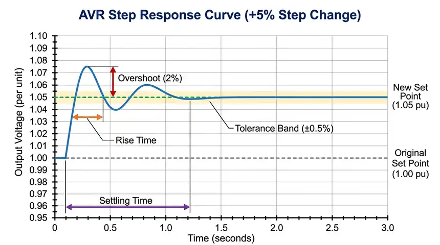
9.3 Step Response Test
This test evaluates the AVR’s dynamic performance. A small step change (usually ±5%) is applied to the voltage reference, and the generator’s voltage response is recorded. The test measures:
- Rise time: Time to reach 90% of the final value
- Settling time: Time for the voltage to settle within ±0.5% of the final value
- Overshoot: Maximum voltage excursion above the final value
9.4 Frequency Response Test
This test measures the AVR’s gain and phase characteristics over a range of frequencies (usually 0.01 Hz to 10 Hz). It helps verify the stability margins of the control loop and detect any tendency toward oscillations.
10. Practical Applications of Automatic Voltage Regulators
AVRs are used in a wide variety of applications across different industries. Here are some common ones.
10.1 Power Generation Plants
Every synchronous generator in a power plant has an AVR as part of its excitation system. The AVR maintains the generator terminal voltage, manages reactive power output, and provides protection against abnormal operating conditions.
10.2 Industrial Manufacturing
Factories with sensitive equipment such as CNC machines, robotic arms, and PLC-controlled processes require a stable voltage supply. Servo-controlled or static AVRs are installed at the main incoming supply or at individual machine feeders to maintain voltage stability.
10.3 Hospitals and Healthcare Facilities
Medical equipment like MRI machines, CT scanners, and ventilators are highly sensitive to voltage fluctuations. AVRs are installed to provide a clean and stable power supply to these life-saving devices.
10.4 Data Centers and IT Infrastructure
Servers, storage systems, and networking equipment in data centers require a stable voltage with minimal fluctuations. Static AVRs with fast response times are commonly used in data center power distribution systems.
10.5 Renewable Energy Systems
Wind turbines and solar inverters connected to the grid through synchronous generators or grid-tied inverters use AVRs to maintain voltage stability at the point of interconnection. This is especially important in weak grid areas where voltage fluctuations are more pronounced.
10.6 Marine and Offshore Applications
Ships and offshore platforms use diesel generators with AVRs to supply power for propulsion systems, drilling equipment, and onboard facilities. The harsh operating environment requires AVRs with robust construction and wide operating temperature ranges.
11. ANSI/IEEE Standards for Automatic Voltage Regulators
Several industry standards govern the design, testing, and application of AVRs. These standards are published by organizations such as IEEE, ANSI, IEC, and NEMA.
11.1 ANSI/IEEE C50.13
This standard covers the requirements for cylindrical-rotor synchronous generators. It includes specifications for voltage regulation, excitation systems, and AVR performance.
11.2 IEEE 421.1
IEEE 421.1 – Definitions for Excitation Systems for Synchronous Machines. This standard provides standardized terminology for excitation systems, including AVR-related terms.
11.3 IEEE 421.2
IEEE 421.2 – Guide for Identification, Testing, and Evaluation of the Dynamic Performance of Excitation Control Systems. This standard describes methods for testing the dynamic performance of AVRs. It covers step response tests, frequency response tests, and large-signal disturbance tests.
11.4 IEEE 421.4
IEEE 421.4 – Guide for the Preparation of Excitation System Specifications. This guide helps engineers prepare procurement specifications for excitation systems and AVRs.
11.5 IEEE 421.5
IEEE 421.5 – Recommended Practice for Excitation System Models for Power System Stability Studies. This standard provides mathematical models for different types of excitation systems and AVRs. These models are used in power system simulation software for stability analysis.
11.6 IEC 60034-16
This IEC standard covers the excitation systems for synchronous machines, including AVR requirements and testing procedures.
11.7 ANSI Device Numbers Related to AVR Functions
The ANSI device numbering system assigns specific numbers to protection and control devices. Here are some device numbers commonly associated with AVR functions:
- ANSI 90 – Regulating Device: This number is assigned to the automatic voltage regulator itself.
- ANSI 59 – Overvoltage Relay: Protects against excessive voltage at the generator terminals.
- ANSI 27 – Undervoltage Relay: Protects against low voltage at the generator terminals.
- ANSI 40 – Loss of Excitation Relay (Loss of Field): Detects the failure of the excitation system or AVR.
- ANSI 24 – Volts per Hertz Relay (V/Hz): Protects the generator and transformer from overfluxing caused by high voltage at low frequency.
12. Conclusion
Automatic Voltage Regulators are a fundamental part of any power generation and distribution system. They keep the output voltage stable and protect electrical equipment from the damaging effects of voltage fluctuations. From simple electromechanical regulators used in small commercial buildings to advanced digital AVRs controlling large synchronous generators in power plants, these devices serve a wide range of applications.
Selecting the right AVR requires a clear understanding of the application requirements, load characteristics, and environmental conditions. Proper commissioning, testing, and maintenance are equally important to get the best performance from an AVR throughout its service life.
13. Frequently Asked Questions (FAQs)
The main function of an AVR is to maintain a constant output voltage from a generator or power source by automatically adjusting the excitation current or transformer tap position in response to load changes.
A static AVR uses semiconductor devices (thyristors, IGBTs) with no moving parts and offers a fast response time. A servo-controlled AVR uses a motor-driven variable transformer and has a slower response time but can handle a wider input voltage range.
Yes, but both AVRs must be set with compatible droop settings and voltage set points. Mismatched settings can cause unequal reactive power sharing and instability. It is best to use identical AVR types for parallel operation.
ANSI device number 90 is assigned to the regulating device, which includes the AVR. Related protection functions include ANSI 59 (overvoltage), ANSI 27 (undervoltage), ANSI 40 (loss of field), and ANSI 24 (V/Hz).
AVR testing should be performed during commissioning and then at regular intervals, usually every 1 to 2 years. Maintenance includes cleaning, checking connections, verifying calibration, and testing protection functions.
If the AVR fails, the generator may lose voltage regulation. Depending on the failure mode, the voltage could rise to dangerous levels (if field current goes to maximum) or drop to zero (if field current is lost). Most modern AVRs include fail-safe features that trip the excitation system upon AVR failure.
A V/Hz limiter prevents the voltage-to-frequency ratio from exceeding a safe limit. This protects the generator and step-up transformer from overfluxing, which can damage the magnetic core.
An AVR directly controls the reactive power output of a synchronous generator by adjusting the field excitation. Increasing excitation causes the generator to supply more reactive power (lagging), which can improve the power factor at the point of connection.
A modern digital AVR has a response time of approximately 20 to 50 milliseconds for a step change in voltage reference. This is fast enough for most power generation applications.
An AVR and a voltage stabilizer serve similar purposes (maintaining stable voltage), but they are not the same. An AVR is specifically designed for generator excitation control, while a voltage stabilizer is a standalone device used to regulate the supply voltage from a utility or other source.