Every electrical machine converts energy from one form to another. During this conversion process, some energy is always lost. One of the most common and measurable forms of energy loss in electrical machines is copper loss. This loss occurs in the windings of transformers, motors, generators, and other electromagnetic devices. It directly affects the efficiency, thermal performance, and operating cost of electrical equipment.
Copper loss is a resistive loss. It happens because the conductors used in windings have electrical resistance. Current flowing through these conductors produces heat. This heat represents wasted energy that does not contribute to useful work.
In this technical guide, we will discuss everything you need to know about copper loss, including its working principle, calculation methods, factors affecting it, reduction techniques, applications in different machines, testing methods, and relevant industry standards. Practical examples are included throughout to help you apply these concepts in real-world scenarios confidently.
1. What is Copper Loss?
Copper loss is the electrical energy dissipated as heat in the windings of an electrical machine due to the resistance of the conductors. The conductors are usually made of copper or aluminum. The name “copper loss” comes from the traditional use of copper wire in electrical windings.
This loss is also called I²R loss or resistive loss. It is directly proportional to the square of the current flowing through the winding and the resistance of that winding. Every electrical device with a winding like transformers, induction motors, DC motors, generators, solenoids, etc., experiences copper loss during operation.
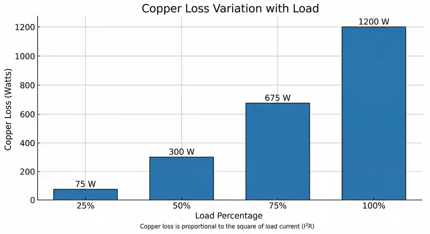
Copper loss is a variable loss. It changes with the load on the machine. At no load, the current is small and copper loss is minimal. At full load, the current increases and so does the copper loss. This characteristic makes copper loss different from core loss (iron loss), which remains approximately constant regardless of the load.
2. Working Principle of Copper Loss
The working principle behind copper loss is simple and rooted in Ohm’s Law and Joule’s Law. Every conductor has some finite resistance, no matter how good the material is. Pure copper has a resistivity of about 1.68 × 10⁻⁸ Ω·m at 20°C. Aluminum has a higher resistivity of about 2.82 × 10⁻⁸ Ω·m.
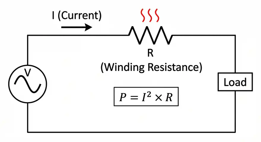
Electric current flowing through a resistive conductor causes electrons to collide with the atomic lattice of the material. These collisions convert electrical energy into thermal energy. This is described by Joule’s first law:
\(\boxed{P = I^2 \times R}\)
Where:
- \(P\) = Power loss in watts (W)
- \(I\) = Current through the conductor in amperes (A)
- \(R\) = Resistance of the conductor in ohms (Ω)
The heat generated raises the temperature of the winding. If not properly managed, this temperature rise can degrade the insulation, reduce the lifespan of the machine, and even cause failure.
2.1 Practical Example
Consider a transformer winding with a resistance of 0.5 Ω carrying a current of 10 A. The copper loss in that winding is:
\(P = (10)^2 \times 0.5 = 50 \text{ W}\)
This 50 watts of power is completely wasted as heat. It does not contribute to the transformer’s output.
3. Formula and Calculation of Copper Loss
The basic formula for copper loss is straightforward. However, the calculation varies slightly depending on the type of machine and the number of windings involved.
3.1 Single Winding
For a single winding:
\(P_{cu} = I^2 \times R\)
3.2 Transformer (Two Windings)
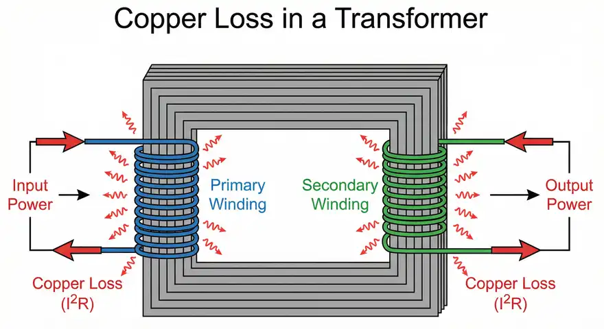
A transformer has a primary winding and a secondary winding. The total copper loss is the sum of losses in both windings:
\(P_{cu(total)} = I_1^2 \times R_1 + I_2^2 \times R_2\)
Where:
- \(I_1\) and \(R_1\) are the current and resistance of the primary winding
- \(I_2\) and \(R_2\) are the current and resistance of the secondary winding
3.3 Three-Phase Machine
For a three-phase motor or generator with balanced load:
\(P_{cu} = 3 \times I^2 \times R\)
Where \(I\) is the phase current and \(R\) is the resistance per phase.
3.4 Practical Example
A three-phase induction motor has a stator winding resistance of 2 Ω per phase. The motor draws a phase current of 15 A. The stator copper loss is:
\(P_{cu} = 3 \times (15)^2 \times 2 = 3 \times 225 \times 2 = 1,350 \text{ W}\)
This is 1.35 kW of power lost as heat in the stator windings alone. The rotor will have additional copper loss depending on the slip and rotor resistance.
4. Copper Loss in Transformers
Transformers are one of the most common devices where copper loss is measured and analyzed. In a power transformer, copper loss determines how efficiently the transformer transfers energy from the primary side to the secondary side.
4.1 Short Circuit Test
The copper loss of a transformer is measured using the short circuit test (also called the impedance test). In this test:
- The secondary winding is short-circuited.
- A reduced voltage is applied to the primary winding.
- The voltage is gradually increased until the rated current flows.
- The wattmeter reading at this point gives the full-load copper loss.
The voltage required to circulate the rated current during the short circuit test is called the impedance voltage. It is usually expressed as a percentage of the rated voltage.
4.2 Practical Example
A 50 kVA, 11 kV/415 V transformer has the following short circuit test results:
- Applied voltage: 500 V
- Current: 4.55 A (rated primary current)
- Power: 600 W
The full-load copper loss of this transformer is 600 watts.
4.3 Copper Loss at Different Loads
Copper loss varies with the square of the load fraction. If a transformer operates at a fraction \(“x”\) of its full load, the copper loss at that load is:
\(P_{cu(x)} = x^2 \times P_{cu(FL)}\)
For a transformer with 600 W full-load copper loss operating at half load (x = 0.5):
\(P_{cu} = (0.5)^2 \times 600 = 0.25 \times 600 = 150 \text{ W}\)
This relationship is important for calculating all-day efficiency of distribution transformers that operate at varying loads throughout the day.
5. Copper Loss in Electric Motors
Electric motors experience copper loss in both the stator and rotor windings. The total copper loss in a motor directly affects its efficiency and thermal rating.
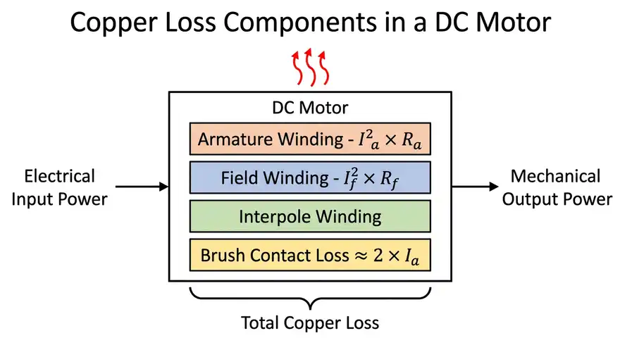
5.1 DC Motors
In a DC motor, copper loss occurs in:
- Armature winding \((I_a^2 \times R_a)\)
- Field winding \((I_f^2 \times R_f)\)
- Interpole winding (if present)
- Compensating winding (if present)
- Brush contact loss (often approximated as \(2 \times I_a\) for carbon brushes)
The armature copper loss is usually the largest component because the armature carries the load current.
5.2 Induction Motors
In a three-phase induction motor, copper loss occurs in:
- Stator copper loss: \(3 \times I_1^2 \times R_1\)
- Rotor copper loss: Slip × Rotor input power
An interesting relationship exists in induction motors: rotor copper loss is directly proportional to slip.
\(P_{\text{rotor_cu}} = s \times P_{\text{rotor_input}}\)
Where \(s\) is the slip of the motor. This means that at higher slip values, the rotor copper loss increases. This is one reason why induction motors become less efficient at loads that cause higher slip.
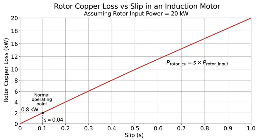
5.3 Practical Example
A three-phase induction motor has a rotor input power of 20 kW and operates at a slip of 4%. The rotor copper loss is:
\(P_{\text{rotor_cu}} = 0.04 \times 20,000 = 800 \text{ W}\)
The mechanical power developed by the rotor is:
\(P_{mech} = 20,000 – 800 = 19,200 \text{ W} = 19.2 \text{ kW}\)
6. Copper Loss in Generators
Generators also experience copper loss in their armature and field windings. In a synchronous generator, the field winding is excited by a DC source, and the armature carries the load current. The copper loss calculation follows the same I²R principle.
For a synchronous generator:
- Armature copper loss: \(3 \times I_a^2 \times R_a\) (for three-phase)
- Field copper loss: \(V_f \times I_f\) (where \(V_f\) is the field voltage and \(I_f\) is the field current)
In large power station generators rated at hundreds of megawatts, even a small percentage of copper loss translates into a large amount of wasted power and heat. Efficient cooling systems using hydrogen gas or water-cooled conductors are used in such machines to remove the heat produced by copper loss.
7. Factors Affecting Copper Loss
Several factors influence the magnitude of copper loss in any electrical machine. Engineers must consider these factors during design and operation.
7.1 Load Current
Copper loss is proportional to the square of the current. Doubling the current increases the copper loss by four times. This makes copper loss the dominant loss at high loads.
7.2 Conductor Resistance
Higher resistance leads to higher copper loss. Resistance depends on:
- Material: Copper has lower resistance than aluminum.
- Length: Longer conductors have higher resistance.
- Cross-sectional area: Thinner conductors have higher resistance.
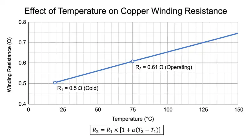
7.3 Temperature
The resistance of copper increases with temperature. The temperature coefficient of resistance for copper is approximately 0.00393 per °C at 20°C. As the machine heats up during operation, the resistance increases, and copper loss also increases.
The resistance at temperature \(T_2\) can be calculated from the resistance at temperature \(T_1\):
\(R_2 = R_1 \times [1 + \alpha \times (T_2 – T_1)]\)
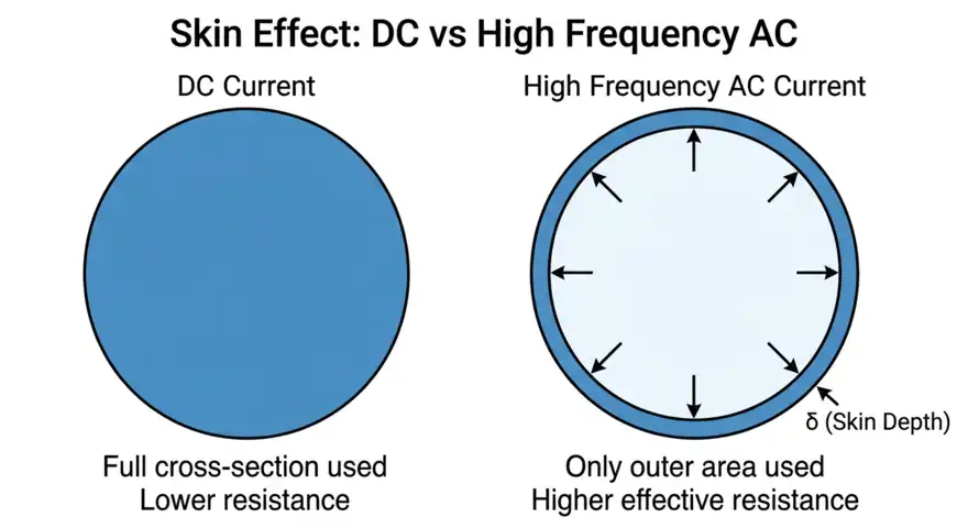
7.4 Skin Effect and Proximity Effect
At higher frequencies, the current tends to flow near the surface of the conductor (skin effect). This effectively reduces the usable cross-sectional area and increases the AC resistance. The proximity effect, caused by nearby conductors, further increases losses. These effects are more pronounced in high-frequency transformers and power electronic applications.
7.5 Harmonics
Non-sinusoidal currents contain harmonic components. Each harmonic frequency increases the effective resistance due to skin effect. The total copper loss increases because each harmonic contributes its own I²R loss. This is a common problem in systems with variable frequency drives and power electronic converters.
8. How to Reduce Copper Loss
Reducing copper loss improves machine efficiency, reduces operating temperatures, and lowers energy costs. Here are proven methods to minimize copper loss in electrical machines.
8.1 Use Larger Cross-Section Conductors
A larger conductor cross-section reduces resistance. This directly reduces copper loss. However, larger conductors increase the size, weight, and material cost of the machine. Engineers must balance efficiency improvement against cost.
8.2 Use Higher Conductivity Materials
Copper has a conductivity of about 5.96 × 10⁷ S/m. It is preferred over aluminum (conductivity 3.5 × 10⁷ S/m) in applications where efficiency is a priority. Some high-performance machines use silver-plated conductors for further reduction.
8.3 Reduce Winding Length
Shorter winding paths mean less resistance. Compact machine designs with optimized winding layouts can reduce the total length of conductor needed.
8.4 Improve Cooling
Better cooling keeps the conductor temperature low. Lower temperature means lower resistance and lower copper loss. Forced air cooling, oil cooling, and water cooling are common methods.
8.5 Operate at Optimal Loading
Copper loss increases with load. Operating a machine at or near its rated load ensures the best efficiency. Oversized machines running at light loads may have poor efficiency due to the dominance of core losses, but undersized machines running above rated load will have excessive copper loss.
8.6 Use Litz Wire for High-Frequency Applications
Litz wire consists of many thin, individually insulated strands woven together. It reduces skin effect and proximity effect losses at high frequencies. This is widely used in switch-mode power supplies, wireless charging coils, and high-frequency transformers.
8.7 Reduce Harmonic Content
Using harmonic filters, active front-end rectifiers, or multi-pulse converter topologies reduces the harmonic content in the current waveform. Lower harmonic distortion means lower additional copper losses.
9. Copper Loss vs. Iron Loss
It is helpful to compare copper loss with iron loss (core loss) since both are major loss components in electrical machines.
| Parameter | Copper Loss | Iron Loss |
|---|---|---|
| Also called | I²R loss, resistive loss | Core loss, magnetic loss |
| Location | Windings (conductors) | Core (laminated steel) |
| Depends on | Load current | Supply voltage and frequency |
| Nature | Variable loss | Approximately constant loss |
| Measurement | Short circuit test (transformer) | Open circuit test (transformer) |
| Reduction method | Larger conductors, better materials | Thinner laminations, better core material |
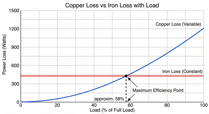
The maximum efficiency of a transformer occurs at the load where copper loss equals iron loss. This is an important design criterion.
Load at maximum efficiency:
\(x = \sqrt{\dfrac{P_{iron}}{P_{cu(FL)}}}\)
9.1 Practical Example
A transformer has an iron loss of 300 W and a full-load copper loss of 1,200 W. Maximum efficiency occurs at:
\(x = \sqrt{\dfrac{300}{1200}} = \sqrt{0.25} = 0.5\)
Maximum efficiency occurs at 50% of full load. This information helps engineers select the right transformer rating for a given application.
10. Relevant Industry Standards
Several ANSI and IEEE standards address copper loss measurement, calculation, and limits in electrical machines.
10.1 For Transformers
- ANSI/IEEE C57.12.00 — General requirements for liquid-immersed distribution, power, and regulating transformers. This standard specifies how to measure and report losses, including copper loss.
- ANSI/IEEE C57.12.90 — Standard test code for liquid-immersed distribution, power, and regulating transformers. It details the short circuit test procedure for measuring copper loss.
- IEEE C57.110 — Recommended practice for establishing liquid-filled and dry-type power and distribution transformer capability under non-sinusoidal load currents. This standard addresses additional copper losses due to harmonics.
10.2 For Rotating Machines
- IEEE 112 — Standard test procedure for polyphase induction motors and generators. It includes methods for segregating losses, including stator and rotor copper loss.
- IEEE 115 — Guide for test procedures for synchronous machines. It covers copper loss determination in synchronous generators and motors.
- NEMA MG 1 — Motors and generators. This standard provides performance specifications, including efficiency ratings that account for copper loss.
10.3 For Energy Efficiency
- IEC 60034-30-1 — Rotating electrical machines – efficiency classes of line-operated AC motors. Defines IE1 through IE4 efficiency classes, where copper loss is a major factor in the efficiency rating.
- DOE 10 CFR 431 — U.S. Department of Energy regulations for energy conservation standards for distribution transformers. These regulations set minimum efficiency levels that directly limit allowable copper losses.
11. Testing and Measurement of Copper Loss
Accurate measurement of copper loss is necessary for quality control, efficiency verification, and performance evaluation.
11.1 Transformer — Short Circuit Test
As described earlier, the short circuit test is the standard method. The measured power at rated current gives the copper loss directly. The test must be performed at the reference temperature specified in the standard (usually 75°C or 85°C). If the test is done at a different temperature, the measured copper loss must be corrected using the temperature correction formula:
\(P_{cu(ref)} = P_{cu(test)} \times \dfrac{T_{ref} + 234.5}{T_{test} + 234.5}\)
This formula is for copper conductors. The constant 234.5 is specific to copper. For aluminum, the constant is 225.
11.2 Motor — Locked Rotor Test
For induction motors, the locked rotor test (similar to the short circuit test in transformers) helps determine the copper loss. The rotor is held stationary, and reduced voltage is applied until rated current flows. The power input minus the core loss at reduced voltage gives the copper loss.
11.3 DC Resistance Measurement
The resistance of each winding can be measured using a DC resistance meter or a Kelvin bridge. Once the resistance is known, the copper loss at any current can be calculated using the I²R formula. This method is simple and widely used.
The DC resistance should be measured at a known temperature and corrected to the reference temperature for accurate loss calculation.
12. Practical Impact of Copper Loss on Energy Costs
Copper loss has a direct financial impact, especially in large industrial installations and power distribution systems. Let us calculate the annual cost of copper loss for a practical scenario.
12.1 Practical Example
A 1,000 kVA distribution transformer has a full-load copper loss of 10 kW. The transformer operates at an average load of 70% of its rated capacity for 8,000 hours per year. The electricity cost is $0.10 per kWh.
Step 1: Calculate copper loss at 70% load.
\(P_{cu} = (0.7)^2 \times 10 = 0.49 \times 10 = 4.9 \text{ kW}\)
Step 2: Calculate annual energy lost.
\(\text{Energy} = 4.9 \times 8,000 = 39,200 \text{ kWh}\)
Step 3: Calculate annual cost.
\(\text{Cost} = 39,200 \times $0.10 = $3,920 \text{ per year}\)
Over a 25-year service life, this amounts to $98,000 in wasted energy from copper loss alone in a single transformer. This demonstrates why selecting energy-efficient transformers with lower copper loss is a smart investment for industrial and utility applications.
13. Copper Loss in Power Transmission and Distribution
Copper loss is not limited to machines. It also occurs in power transmission lines, distribution cables, and bus bars. Every length of conductor carrying current experiences I²R loss.
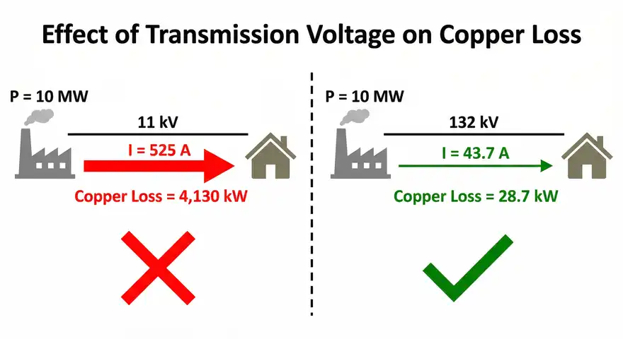
In power transmission, this is one of the main reasons why electricity is transmitted at high voltage. Raising the voltage reduces the current for the same amount of power. Since copper loss depends on the square of the current, higher transmission voltage results in dramatically lower line losses.
13.1 Practical Example
A power plant needs to transmit 10 MW of power. The transmission line has a resistance of 5 Ω.
Case 1: Transmission at 11 kV
\(I = \dfrac{10,000,000}{(\sqrt{3} \times 11,000)} = 525 \text{ A}\)
\(P_{loss} = 3 \times (525)^2 \times 5 = 4,134,375 \text{ W} ≈ 4.13 \text{ MW}\)
Case 2: Transmission at 132 kV
\(I = \dfrac{10,000,000}{(\sqrt{3} \times 132,000)} = 43.7 \text{ A}\)
\(P_{loss} = 3 \times (43.7)^2 \times 5 = 28,672 \text{ W} ≈ 28.7 \text{ kW}\)
The difference is enormous. Transmitting at 132 kV reduces the line copper loss from 4.13 MW to just 28.7 kW. This is why high-voltage transmission is the standard practice in electrical power systems.
14. Conclusion
Copper loss is one of the most common and measurable forms of energy loss in electrical systems. It occurs wherever current flows through a conductor with resistance. From small transformers to large power station generators and long transmission lines, copper loss affects the efficiency, temperature, and operating cost of every electrical installation.
Engineers must account for copper loss during the design phase by selecting appropriate conductor sizes, materials, and cooling methods. The I²R formula provides a simple yet powerful tool for calculating these losses.
Reducing copper loss is not just a technical goal, it is also a financial one. Lower losses mean lower electricity bills, longer equipment life, and reduced environmental impact. A solid grasp of copper loss fundamentals is a valuable skill for any practicing electrical engineer.
15. Frequently Asked Questions (FAQs)
Copper loss in a transformer is the power dissipated as heat in the primary and secondary windings due to the resistance of the copper conductors. It is measured using the short circuit test and is calculated using the formula P = I²R for each winding.
Copper loss is called I²R loss because it is calculated by multiplying the square of the current (I²) by the resistance (R) of the conductor. This relationship comes from Joule’s Law of heating.
Copper loss is a variable loss. It changes with the load current. At higher loads, the current increases and copper loss increases proportionally to the square of the current. At no load, copper loss is very small.
Copper loss can be minimized by using conductors with larger cross-sectional area, choosing materials with higher conductivity (copper over aluminum), improving cooling systems, reducing winding length, and minimizing harmonic distortion in the supply current.
Copper loss occurs in the windings and depends on the load current. Iron loss occurs in the magnetic core and depends on the supply voltage and frequency. Copper loss is a variable loss, and iron loss is approximately a constant loss.
Maximum efficiency occurs at the load where copper loss equals iron loss. The load fraction can be calculated using x = √(P_iron / P_cu at full load).
Yes. Copper loss occurs in any circuit where current flows through a conductor with resistance. It is not limited to AC circuits. DC motors, DC generators, and DC power cables all experience copper loss.
High-voltage transmission reduces the current for the same power level. Since copper loss is proportional to the square of the current, reducing the current by increasing the voltage leads to a large reduction in transmission line losses.