Every electrical circuit needs a source of energy to function. This energy can be delivered in two fundamental ways: through a voltage source or a current source. Both serve the purpose of powering a circuit, but they do it in very different ways. A voltage source maintains a constant voltage across its terminals regardless of the current flowing through the circuit. A current source, on the other hand, delivers a constant current to the circuit regardless of the voltage across its terminals.
In this technical guide, we will discuss everything you need to know about the difference between voltage source and current source, including their definitions, characteristics, internal resistance behavior, circuit representations, ideal vs. practical models, real-world examples, conversion techniques, and applications. Practical examples are included throughout to help you apply these concepts in real-world scenarios confidently.
1. What is a Voltage Source?
A voltage source is a two-terminal device that maintains a fixed voltage across its terminals no matter how much current is drawn from it. The most common example is a battery. A 12V car battery, for instance, is designed to provide 12 volts across its terminals whether you connect a small LED or a large starter motor.
In an ideal voltage source, the output voltage remains perfectly constant for any load condition. The internal resistance of an ideal voltage source is zero. This means there is no voltage drop inside the source itself, and all the voltage appears across the external load.
In practice, no voltage source is truly ideal. Every real battery or power supply has some internal resistance. As more current is drawn, a small voltage drop occurs across this internal resistance, and the terminal voltage decreases slightly. This is why a car battery’s voltage dips a little when you crank the engine.
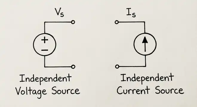
The schematic symbol for an independent voltage source is a circle with “+” and “−” signs inside it. A dependent (controlled) voltage source is represented by a diamond shape with polarity markings.
2. What is a Current Source?
A current source is a two-terminal device that delivers a constant current to the circuit connected across its terminals. The voltage across a current source adjusts automatically to maintain the set current value through the load.
An ideal current source has infinite internal resistance. This means no matter how the load resistance changes, the source forces the same amount of current through the circuit. The voltage across the source simply rises or falls as needed to keep the current constant.
A practical example of a current source is a transistor-based constant current circuit. LED driver circuits often use current sources to deliver a fixed current (say, 20 mA) to an LED regardless of the forward voltage variation between different LEDs.
In real life, a perfect current source does not exist either. Every practical current source has a finite (but very high) internal resistance. As the load resistance increases beyond a certain point, the source can no longer maintain the constant current because the required voltage would exceed its supply limits.
The schematic symbol for an independent current source is a circle with an arrow inside it, indicating the direction of current flow. A dependent current source uses a diamond shape with an arrow.
3. Differences Between Voltage Source and Current Source
Here is a detailed comparison between voltage sources and current sources across several parameters.
3.1 Output Parameter
A voltage source maintains a constant voltage. A current source maintains a constant current. This is the most fundamental difference between the two.
3.2 Internal Resistance
An ideal voltage source has zero internal resistance. An ideal current source has infinite internal resistance. In practical terms, a good voltage source has very low internal resistance, and a good current source has very high internal resistance.
3.3 Behavior with Load Changes
If you change the load resistance connected to a voltage source, the current changes but the voltage stays the same (ideally). If you change the load resistance connected to a current source, the voltage changes but the current stays the same (ideally).
For example, consider a 10V ideal voltage source connected to a 5Ω resistor. The current is 10V / 5Ω = 2A. Now change the resistor to 10Ω. The current becomes 10V / 10Ω = 1A. The voltage stayed at 10V in both cases.
Now consider a 2A ideal current source connected to a 5Ω resistor. The voltage across the resistor is 2A × 5Ω = 10V. Change the resistor to 10Ω. The voltage becomes 2A × 10Ω = 20V. The current stayed at 2A in both cases.
3.4 Series and Parallel Connection Rules
Voltage sources can be connected in series to add their voltages. Two 6V batteries in series give 12V. Voltage sources should not be connected in parallel unless they have the exact same voltage, because even a small voltage difference would cause very large circulating currents (due to very low internal resistance).
Current sources can be connected in parallel to add their currents. Two 1A current sources in parallel give 2A. Current sources should not be connected in series unless they deliver the exact same current, because a mismatch would violate Kirchhoff’s Current Law and result in an undefined condition.
3.5 Short Circuit and Open Circuit Behavior
A voltage source should never be short-circuited. An ideal voltage source with zero internal resistance would deliver infinite current into a short circuit, which in the real world means a blown fuse, tripped circuit breaker, or damaged equipment. This is why short circuit protection and overcurrent protection are standard features in modern power supplies.
A current source should never be open-circuited. An ideal current source would develop infinite voltage across an open circuit to maintain its constant current. In practice, this leads to voltage spikes and damage to the source. This is why circuits powered by current sources always need a defined load path.
3.6 Circuit Model Representation
A practical voltage source is modeled as an ideal voltage source in series with a small resistance. A practical current source is modeled as an ideal current source in parallel with a large resistance.
3.7 Thevenin and Norton Equivalents
Any linear circuit can be reduced to a Thevenin equivalent (a voltage source in series with a resistance) or a Norton equivalent (a current source in parallel with a resistance). These two representations are interchangeable using the relationship:
\(\boxed{V_{th} = I_N \times R_{th}}\)
Where \(V_{th}\) is the Thevenin voltage, \(I_N\) is the Norton current, and \(R_{th}\) is the Thevenin resistance (which equals the Norton resistance).
4. Summary Table: Voltage Source vs. Current Source
| Parameter | Voltage Source | Current Source |
|---|---|---|
| Output | Constant voltage | Constant current |
| Internal resistance (ideal) | Zero (0 Ω) | Infinite (∞ Ω) |
| Internal resistance (practical) | Very low | Very high |
| Effect of load change | Current changes | Voltage changes |
| Dangerous condition | Short circuit | Open circuit |
| Series connection | Voltages add up | Not allowed (unless equal currents) |
| Parallel connection | Not allowed (unless equal voltages) | Currents add up |
| Practical model | Ideal source + series resistance | Ideal source + parallel resistance |
| Thevenin/Norton | Thevenin equivalent | Norton equivalent |
| Common examples | Battery, generator, DC power supply | Transistor current mirror, LED driver |
5. Source Transformation: Converting Between Voltage and Current Sources
One of the most useful techniques in circuit analysis is source transformation. You can convert a voltage source with a series resistance into an equivalent current source with a parallel resistance, and vice versa.
5.1 Voltage Source to Current Source
If you have a voltage source \(V_s\) in series with resistance \(R_s\), the equivalent current source is:
\(I_s = \dfrac{V_s}{R_s}\) (in parallel with \(R_s\))
5.2 Current Source to Voltage Source
If you have a current source \(I_s\) in parallel with resistance \(R_s\), the equivalent voltage source is:
\(V_s = I_s \times R_s\) (in series with \(R_s\))
5.3 Practical Example
Suppose you have a 12V battery with an internal resistance of 2Ω. The equivalent Norton (current source) model would be:
\(I_s = \dfrac{12V}{2Ω} = 6A\), in parallel with 2Ω.
Both models will produce the same current and voltage at the external load terminals. The choice of model depends on which makes the circuit analysis easier. Source transformation is heavily used in mesh analysis, nodal analysis, and network simplification.
6. Real-World Examples and Applications
6.1 Voltage Source Examples
- Batteries: A 1.5V AA battery, a 9V battery, and a 12V car battery are all voltage sources. They attempt to maintain a fixed terminal voltage.
- Wall outlet (AC mains): The 120V/60Hz supply in the United States or the 230V/50Hz supply in the UK is an AC voltage source.
- DC power supply units: Bench power supplies used in electronics labs are regulated voltage sources. Brands like Keysight, Rigol, and Siglent manufacture precision DC power supplies with very low output impedance.
- Solar panels: A solar panel acts approximately as a voltage source under certain load conditions (near open circuit). However, its behavior is more complex and shifts toward a current source characteristic under heavy load.
6.2 Current Source Examples
- LED drivers: High-power LED lighting systems use constant current drivers. An LED driver rated at 350 mA will push exactly 350 mA through the LED string regardless of the total forward voltage.
- Transistor current mirrors: In integrated circuit design, current mirrors are used everywhere to bias transistors. The MOSFET current mirror and the Wilson current mirror are common topologies in analog IC design.
- Photodiodes: A photodiode operating in photovoltaic or photoconductive mode behaves like a current source. The output current is proportional to the incident light intensity.
- 4-20 mA industrial transmitters: In process control and industrial automation, sensors transmit their readings as a current signal between 4 mA and 20 mA. This current loop behaves as a current source and is resistant to noise and voltage drops along long cable runs.
7. Practical Circuit Example
Let us walk through a simple circuit to see both sources in action.
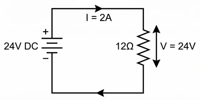
Example 1: Voltage Source Driving a Resistive Load
A 24V DC power supply (voltage source) is connected to a 12Ω resistor.
- Voltage across the resistor = 24V
- Current through the resistor = 24V / 12Ω = 2A
- Power dissipated by the resistor = 24V × 2A = 48W
If we change the resistor to 24Ω:
- Voltage = 24V (unchanged)
- Current = 24V / 24Ω = 1A
- Power = 24V × 1A = 24W
The voltage stayed constant. The current adjusted according to the load.
Example 2: Current Source Driving a Resistive Load
A 2A constant current source is connected to a 12Ω resistor.
- Current through the resistor = 2A
- Voltage across the resistor = 2A × 12Ω = 24V
- Power = 24V × 2A = 48W
If we change the resistor to 24Ω:
- Current = 2A (unchanged)
- Voltage = 2A × 24Ω = 48V
- Power = 48V × 2A = 96W
The current stayed constant. The voltage adjusted according to the load.
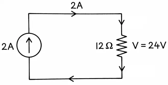
Notice that the current source had to increase its output voltage from 24V to 48V to maintain 2A through the larger resistor. In a practical current source, this is limited by the maximum compliance voltage of the source.
8. Conclusion
Voltage sources and current sources are the two fundamental building blocks of every electrical circuit. A voltage source delivers a constant voltage and has low internal resistance. A current source delivers a constant current and has high internal resistance. These two types of sources behave very differently under varying load conditions, and each has its own set of rules for series and parallel connections.
The ability to distinguish between these sources and convert between their Thevenin and Norton equivalents is a foundational skill in circuit analysis, power electronics, and analog design. Real-world devices like batteries, power supplies, LED drivers, and industrial transmitters all rely on these concepts.
9. Frequently Asked Questions (FAQs)
Yes. Using source transformation, a voltage source V in series with resistance R can be converted to an equivalent current source I = V/R in parallel with the same resistance R.
Zero internal resistance means there is no voltage drop inside the source. All the source voltage appears across the external load, regardless of how much current flows.
Infinite internal resistance means no current is “lost” through the internal path. All the source current flows through the external load, regardless of the load resistance or the voltage developed across the terminals.
Nothing harmful happens. A short circuit has zero resistance, so the voltage across it is zero. The current source simply delivers its rated current through the short circuit at zero voltage. This is actually the normal operating point for measuring the Norton current.
Nothing harmful happens. An open circuit draws zero current. The voltage source simply maintains its rated voltage across the open terminals.
A solar panel has a complex I-V characteristic. Near open circuit, it behaves more like a voltage source. Near short circuit, it behaves more like a current source.
An independent source provides a fixed output regardless of other circuit variables. A dependent source provides an output that is controlled by a voltage or current at another point in the circuit.
Batteries are voltage sources. They are designed to maintain a relatively constant terminal voltage.
Yes, but you need current limiting. Connecting a higher-voltage source directly to a battery can cause excessive charging current.