A Ground Fault Circuit Interrupter commonly known as GFCI, is a protective device designed to prevent electrical shocks and electrocution. This device constantly monitors the flow of electrical current in a circuit and immediately shuts off power when it detects an imbalance between the hot and neutral conductors. The GFCI was first introduced in the 1960s and has since become a standard safety requirement in residential, commercial, and industrial electrical installations.
The primary purpose of a GFCI is to protect people from the dangers of ground faults. A ground fault occurs when electrical current takes an unintended path to the ground often through a person’s body. This can happen when a faulty appliance, damaged wiring, or moisture creates an alternative pathway for electricity. Without a GFCI such incidents can result in severe injury or death within milliseconds.
1. How Does a GFCI Work?
The working principle of a GFCI is based on the detection of current imbalance. Under normal operating conditions the current flowing through the hot conductor should equal the current returning through the neutral conductor. When these two values differ, it indicates that some current is leaking to ground through an unintended path.
Inside a GFCI, there is a small current transformer with two windings. The hot and neutral conductors pass through this transformer’s core. When current flows equally in both conductors, the magnetic fields they create cancel each other out resulting in zero net magnetic flux. However, when a ground fault occurs and current leaks to ground, an imbalance is created. This imbalance produces a net magnetic flux that induces a voltage in the sensing winding.
The induced voltage triggers the electronic circuitry inside the GFCI which then activates a trip mechanism. This mechanism opens the circuit contacts and disconnects power to the load. The entire process happens in approximately 25 to 40 milliseconds which is fast enough to prevent serious injury in most cases.
Example: Imagine you are using a hairdryer near a bathroom sink filled with water. If the hairdryer falls into the water while you are touching it, electrical current could flow through the water and your body to ground. A GFCI outlet would detect this current leakage and cut off power before you receive a dangerous shock.
2. Types of GFCI Devices
GFCI protection is available in several different forms, each suited for specific applications and installation requirements.
| Type | Description | Common Applications |
|---|---|---|
| GFCI Outlet/Receptacle | Replaces standard electrical outlets and provides protection at the point of use | Bathrooms, kitchens, garages, outdoor areas |
| GFCI Circuit Breaker | Installed in the electrical panel and protects the entire circuit | Swimming pool equipment, hot tubs, large outdoor circuits |
| Portable GFCI | Plug-in devices that can be moved between locations | Construction sites, temporary power needs, outdoor power tools |
| Cord-Connected GFCI | Built into the power cord of appliances | Hairdryers, power tools, portable heaters |
| GFCI with Blank Face | Provides protection without an outlet receptacle | Protecting downstream outlets, dedicated circuit protection |
2.1 GFCI Outlet/Receptacle
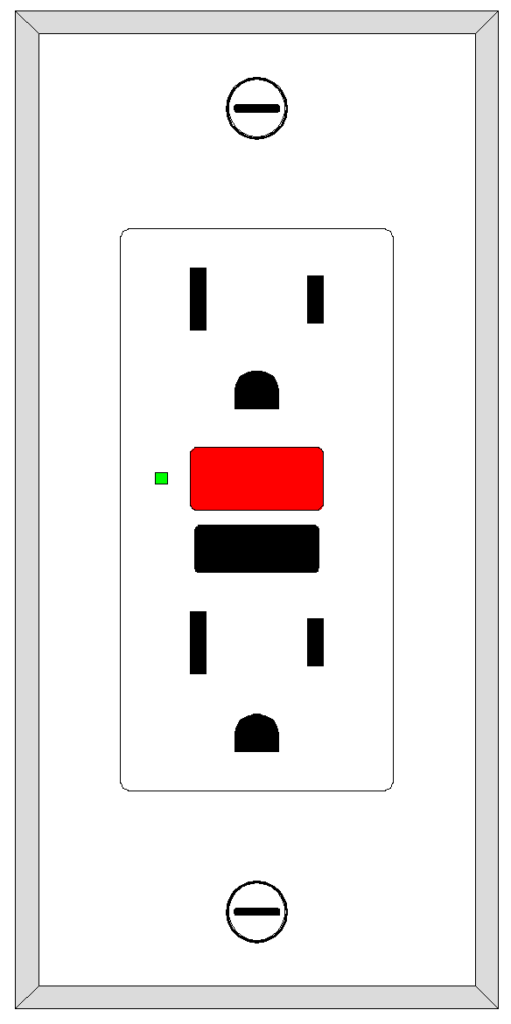
The GFCI receptacle is the most commonly recognized form of ground fault protection. It looks similar to a standard electrical outlet but includes two buttons labeled “TEST” and “RESET” on its face. These receptacles can be wired to protect only the outlet itself or configured to protect additional standard outlets downstream on the same circuit.
2.2 GFCI Circuit Breaker
A GFCI circuit breaker combines overcurrent protection with ground fault protection in a single device. When installed in the main electrical panel, it monitors and protects the entire branch circuit. This type is particularly useful when multiple outlets on a circuit require protection or when the circuit serves equipment in wet locations.
2.3 Portable GFCI
Portable GFCIs are standalone devices that plug into any standard outlet and provide ground fault protection for equipment plugged into them. These are commonly used on construction sites where permanent GFCI protection may not be available. They typically feature multiple outlets and a test/reset mechanism similar to GFCI receptacles.
3. GFCI Technical Specifications
| Parameter | Specification |
|---|---|
| Trip Current (Ground Fault) | 4-6 milliamperes (mA) |
| Maximum Trip Time at 6mA | 25-40 milliseconds |
| Rated Voltage | 120V or 240V (depending on type) |
| Rated Current | 15A, 20A, 30A, or higher |
| Operating Temperature | -35°C to +66°C (typical) |
| Dielectric Strength | 1500V minimum |
| Test Frequency | Monthly (recommended) |
The trip current of 4-6 mA is based on research showing that currents below this threshold are unlikely to cause ventricular fibrillation in healthy adults. The fast trip time prevents prolonged exposure to dangerous current levels.
4. GFCI vs. Standard Circuit Breaker
Many students confuse GFCI protection with standard overcurrent protection provided by regular circuit breakers.
| Feature | Standard Circuit Breaker | GFCI Device |
|---|---|---|
| Primary Function | Overcurrent and short circuit protection | Ground fault protection |
| Trip Sensitivity | 15A, 20A, or higher (rated current) | 4-6 mA |
| What It Detects | Excessive current flow | Current imbalance between hot and neutral |
| Protection Against | Fire hazards, wire damage | Electric shock, electrocution |
| Trip Time | Varies based on overload magnitude | 25-40 milliseconds |
| Installation Location | Electrical panel only | Panel, outlet, or portable |
A standard circuit breaker will not trip during a ground fault if the leakage current is below its rated amperage. For example, if only 100 mA is leaking through a person’s body, a 15A breaker sees no problem while the person could be fatally injured. This is why GFCI protection is required in addition to standard overcurrent protection.
5. Where Are GFCIs Required?
Building codes and electrical standards mandate GFCI protection in locations where the risk of electric shock is elevated due to moisture or proximity to water. The National Electrical Code (NEC) in the United States specifies the following locations for GFCI installation in residential settings.
| Location | NEC Requirement |
|---|---|
| Bathrooms | All receptacles |
| Kitchens | Receptacles serving countertop areas |
| Garages and Accessory Buildings | All receptacles |
| Outdoors | All receptacles |
| Crawl Spaces | All receptacles at or below grade level |
| Unfinished Basements | All receptacles |
| Laundry Areas | Receptacles within 6 feet of sink |
| Pool and Spa Areas | All receptacles within specified distance |
| Boathouses | All receptacles |
| Kitchen Dishwasher Circuits | Branch circuit supplying dishwasher |
Commercial and industrial installations have additional requirements based on the type of occupancy and the nature of work performed. Healthcare facilities, construction sites, and food service establishments all have specific GFCI requirements outlined in various codes and standards.
6. GFCI Installation Procedures
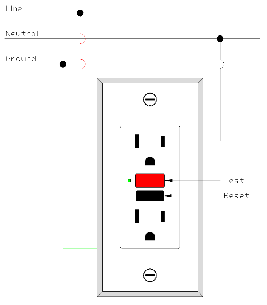
Proper installation of a GFCI receptacle requires attention to correct wiring connections. A GFCI receptacle has two sets of terminals: LINE and LOAD.
6.1 LINE Terminals
The LINE terminals connect to the incoming power from the electrical panel. The hot wire (typically black) connects to the brass-colored LINE terminal, while the neutral wire (typically white) connects to the silver-colored LINE terminal. These connections allow the GFCI to monitor current flow and protect the receptacle itself.
6.2 LOAD Terminals
The LOAD terminals are used to extend GFCI protection to additional standard outlets downstream on the circuit. When properly connected, any outlet fed from these terminals will also be protected by the GFCI. The LOAD terminals are usually covered with a warning tape that should only be removed if downstream protection is needed.
6.3 Installation Steps:
- Turn off power at the circuit breaker and verify with a voltage tester
- Remove the existing outlet from the electrical box
- Identify the LINE wires (coming from the panel) and LOAD wires (going to downstream outlets)
- Connect the LINE hot wire to the brass LINE terminal
- Connect the LINE neutral wire to the silver LINE terminal
- If protecting downstream outlets, connect LOAD wires to the corresponding LOAD terminals
- Connect the ground wire to the green grounding screw
- Mount the GFCI in the box and install the cover plate
- Restore power and test the GFCI using the TEST button
7. Testing and Maintenance of GFCI Devices
Regular testing of GFCI devices is necessary to verify they are functioning correctly. Over time, the electronic components inside a GFCI can degrade, leaving the device unable to trip during an actual ground fault.
7.1 Monthly Testing Procedure
Every GFCI receptacle and circuit breaker has a TEST button that simulates a ground fault condition. Pressing this button should cause the device to trip immediately, cutting off power to the protected circuit. After testing, the RESET button restores power.
Testing Steps:
- Plug a lamp or radio into the GFCI outlet and turn it on
- Press the TEST button firmly
- The device should trip and the lamp/radio should turn off
- Press the RESET button to restore power
- The lamp/radio should turn back on
If the GFCI does not trip when tested, or if it cannot be reset, the device should be replaced immediately. Some newer GFCI receptacles include self-testing features that automatically check functionality and indicate failure through LED indicators.
| GFCI Condition | Indicator | Action Required |
|---|---|---|
| Normal Operation | Green LED or no LED | None |
| Self-Test Passed | Brief click sound | None |
| Self-Test Failed | Red LED or flashing LED | Replace immediately |
| End of Life | Cannot reset after tripping | Replace immediately |
| Tripped State | No power to outlets | Investigate cause and reset |
8. Common GFCI Problems and Troubleshooting
GFCI devices can sometimes trip unexpectedly or fail to function properly.
8.1 Nuisance Tripping
Nuisance tripping refers to GFCI devices tripping when no actual ground fault exists. This can be caused by several factors:
- Moisture in electrical boxes: Water infiltration can create leakage paths that cause the GFCI to detect an imbalance. Outdoor installations and bathroom circuits are particularly susceptible.
- Long circuit runs: Circuits with long wire runs can develop small capacitive leakage currents that accumulate and approach the GFCI trip threshold. This is more common in commercial installations.
- Shared neutral conductors: When multiple circuits share a common neutral wire (multiwire branch circuits), improper wiring can cause GFCIs to trip due to neutral current imbalances.
- Worn or damaged appliances: Older appliances with degraded insulation can leak small amounts of current that trigger GFCI protection.
8.2 GFCI Will Not Reset
When a GFCI refuses to reset after pressing the RESET button, several conditions may be responsible:
| Possible Cause | Solution |
|---|---|
| No power to LINE terminals | Check circuit breaker and wiring |
| Existing ground fault on circuit | Disconnect all loads and reset |
| Miswired LINE and LOAD connections | Correct wiring connections |
| Defective GFCI device | Replace with new GFCI |
| Reversed hot and neutral wires | Correct wiring polarity |
8.3 Troubleshooting Procedure
Example scenario: A homeowner reports that their bathroom GFCI keeps tripping every morning.
- First, unplug all devices from outlets on the protected circuit
- Reset the GFCI and observe if it holds
- If it holds with nothing plugged in, reconnect devices one at a time
- When the tripping device is identified, inspect it for damage or moisture
- If tripping continues with nothing connected, check for moisture in outlet boxes
- Inspect wiring for damage or deterioration
- If wiring appears sound and dry, replace the GFCI
9. GFCI Standards and Certifications
Several organizations publish standards that govern the design, testing, and performance of GFCI devices.
| Standard | Organization | Description |
|---|---|---|
| UL 943 | Underwriters Laboratories | Standard for Ground-Fault Circuit-Interrupters |
| UL 1053 | Underwriters Laboratories | Standard for Ground-Fault Sensing and Relaying Equipment |
| IEC 61008 | International Electrotechnical Commission | Residual current operated circuit-breakers without integral overcurrent protection |
| CSA C22.2 No. 144 | Canadian Standards Association | Ground fault circuit interrupters |
| NEC Article 210.8 | NFPA | GFCI protection requirements in the National Electrical Code |
All GFCI devices sold in North America must be listed by a recognized testing laboratory such as UL or CSA. The listing mark indicates that the device has been tested and meets the applicable safety standards.
10. GFCI Limitations
While GFCIs provide excellent protection against ground faults, they have certain limitations that must be understood.
10.1 Line-to-Line Shocks
A GFCI cannot protect against shock when a person contacts both the hot and neutral conductors simultaneously without a ground path. In this scenario, current flows through the person’s body but returns through the neutral conductor, creating no imbalance for the GFCI to detect.
Example: If someone touches both prongs of a plug while it is partially inserted into an outlet, current flows through their body from hot to neutral. The GFCI sees equal current in both conductors and does not trip.
10.2 Equipment Damage
GFCIs are designed to protect people, not equipment. The trip threshold of 4-6 mA is based on human physiological response to electric current. Equipment can be damaged by ground fault currents below this threshold, and GFCIs will not provide protection in such cases.
11. Conclusion
The Ground Fault Circuit Interrupter is one of the most significant advances in electrical safety for personnel protection. By detecting tiny current imbalances and interrupting power within milliseconds, GFCIs prevent thousands of electrocutions and injuries each year.