Capacitors are one of the most commonly used passive components in electrical and electronic circuits. A faulty capacitor can cause an entire circuit to malfunction. A digital multimeter is the most accessible and practical tool for testing capacitors in the field and in the lab. Most modern multimeters offer capacitance measurement mode, resistance mode, and continuity mode. All three can be used to evaluate the health of a capacitor. The testing method you choose depends on the type of capacitor, its rated value, and the level of accuracy you need.
In this technical guide, we will discuss everything you need to know about testing capacitors with a multimeter, including the working principle behind each test method, step-by-step procedures for different capacitor types, safety precautions, common failure modes, interpretation of readings, and relevant industry standards. Practical examples are included throughout to help you apply these concepts in real-world scenarios confidently.
1. Why Do Capacitors Fail?
Before learning how to test a capacitor, it helps to understand why capacitors fail in the first place. Capacitors degrade over time due to several factors. Heat is one of the primary causes of capacitor failure. Electrolytic capacitors are especially sensitive to temperature. Operating a capacitor above its rated voltage can break down the dielectric material and cause a short circuit internally.
Aging is another common cause. Electrolytic capacitors contain a liquid or gel electrolyte that dries out over time. This causes the capacitance value to drop and the equivalent series resistance (ESR) to increase. A capacitor that has lost a large portion of its rated capacitance is considered “weak” and should be replaced.
Overvoltage transients, reverse polarity connections, and manufacturing defects can also lead to capacitor failure. In some cases, a failed capacitor may show visible signs like bulging, leaking, or burn marks. In other cases, the capacitor may look perfectly normal but still be electrically faulty. That is exactly why electrical testing with a multimeter is necessary.
2. Types of Capacitor Faults
Capacitors can fail in several distinct ways. Each type of fault produces different symptoms and requires a slightly different testing approach. Here are the most common fault types:
Open Circuit: The capacitor has lost its ability to store charge. It behaves as if it is not present in the circuit. This often happens in older electrolytic capacitors where the internal connections have broken.
Short Circuit: The dielectric material between the plates has broken down. The capacitor now acts as a direct conductor. This fault can cause excessive current flow and may damage other components in the circuit.
Leakage: The capacitor allows a small DC current to pass through the dielectric. All capacitors have some leakage, but excessive leakage indicates degradation. This is common in aged electrolytic capacitors.
Reduced Capacitance: The measured capacitance is well below the rated value. This happens due to electrolyte dry-out in electrolytic types or dielectric degradation in film and ceramic types.
High ESR: The equivalent series resistance has increased beyond acceptable limits. The capacitor may still show close to its rated capacitance but performs poorly under AC conditions. A standard multimeter cannot measure ESR directly, but it can detect open and short conditions.
3. Safety Precautions Before Testing
Safety must always come first. Capacitors store electrical energy even after the circuit has been powered off. A charged capacitor can deliver a dangerous or even lethal shock, especially in high-voltage applications like power supplies, motor drives, and power factor correction banks.
Follow these safety steps before testing any capacitor:
- Disconnect power to the circuit completely. Verify that the power source is off using your multimeter’s voltage measurement mode.
- Discharge the capacitor before touching its terminals. Use a discharge resistor appropriate for the voltage rating. For low-voltage capacitors (under 50V), a 1 kΩ to 10 kΩ resistor works well. For high-voltage capacitors, use a higher-rated resistor and exercise extreme caution.
- Wait for the capacitor to discharge fully. Measure the voltage across the terminals with your multimeter. The reading should be 0V or very close to 0V before proceeding.
- Remove the capacitor from the circuit if possible. Testing a capacitor in-circuit can give misleading results because other components connected in parallel may affect the readings.
- Wear appropriate personal protective equipment (PPE), including insulated gloves and safety glasses, especially for high-voltage capacitors.
ANSI Z535.4 provides guidelines for safety signs and labels. Capacitors rated above 100V should always be handled with extra care and should carry appropriate warning labels per ANSI standards.
4. Tools You Will Need
Here is a list of tools required for capacitor testing:
- A digital multimeter (DMM) with capacitance measurement mode (preferred)
- A multimeter with resistance (ohm) measurement mode
- A discharge resistor (appropriate wattage and resistance value)
- Insulated test leads and alligator clips
- Safety gloves and safety glasses
- A clean, dry workspace
Not all multimeters have a dedicated capacitance mode. Budget multimeters often lack this feature. If your multimeter only has resistance and continuity modes, you can still perform basic go/no-go testing on capacitors. However, for accurate capacitance value measurement, a meter with capacitance mode or a dedicated capacitance meter is recommended.
Popular multimeter models that include capacitance measurement are the Fluke 87V, Fluke 117, Klein Tools MM700, and the UNI-T UT139C. These meters can measure capacitance ranging from a few picofarads (pF) to several millifarads (mF).
5. Method 1: Testing a Capacitor Using Capacitance Mode
This is the most accurate and straightforward method for testing a capacitor with a multimeter. If your digital multimeter has a capacitance measurement function (indicated by the “F” or capacitor symbol on the dial), use this method.
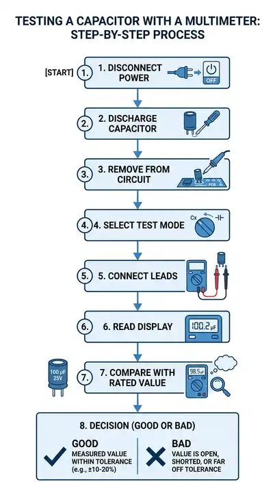
5.1 Step-by-Step Procedure
Step 1: Disconnect the capacitor from the circuit and discharge it completely using a discharge resistor. Verify 0V across the terminals.
Step 2: Set your multimeter dial to the capacitance measurement mode. The symbol looks like two parallel lines or is marked with “F” for Farads.
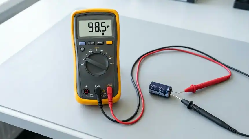
Step 3: Connect the multimeter test leads to the capacitor terminals. For polarized capacitors (electrolytic and tantalum types), connect the red lead to the positive terminal and the black lead to the negative terminal.
Step 4: Read the value displayed on the multimeter screen.
Step 5: Compare the measured value with the rated capacitance printed on the capacitor body.
5.2 How to Interpret the Results
A healthy capacitor should read within ±10% to ±20% of its rated value, depending on the tolerance specified by the manufacturer. For example, a 100 µF capacitor with a ±20% tolerance should read between 80 µF and 120 µF.
If the multimeter displays “OL” (overload) or “Open,” the capacitor is likely open-circuited and should be replaced.
If the multimeter reads 0 µF or a value very close to zero, the capacitor may be short-circuited or completely degraded.
5.3 Practical Example
Suppose you are troubleshooting an AC motor that fails to start. The motor uses a 30 µF run capacitor rated at 370 VAC. You remove the capacitor, discharge it safely, and measure it using your Fluke 87V multimeter in capacitance mode. The meter reads 18 µF. This is a 40% loss in capacitance, well outside the acceptable ±10% tolerance for motor run capacitors. The capacitor is faulty and must be replaced with a new 30 µF, 370 VAC capacitor.
6. Method 2: Testing a Capacitor Using Resistance (Ohm) Mode
If your multimeter does not have a capacitance measurement mode, you can use the resistance mode to perform a basic health check on a capacitor. This method does not give you the exact capacitance value. Instead, it tells you if the capacitor is open, shorted, or functional.
This method works best on electrolytic capacitors with values above 1 µF. It is less effective on very small ceramic or film capacitors because their charging time is too short to observe on the multimeter display.
6.1 Step-by-Step Procedure
Step 1: Remove the capacitor from the circuit and discharge it fully.
Step 2: Set your multimeter to the resistance mode (Ω). Select a high range such as 20 kΩ or 200 kΩ. Some multimeters have auto-ranging, which simplifies this step.
Step 3: Connect the red lead to the positive terminal and the black lead to the negative terminal of the capacitor.
Step 4: Observe the multimeter display carefully.
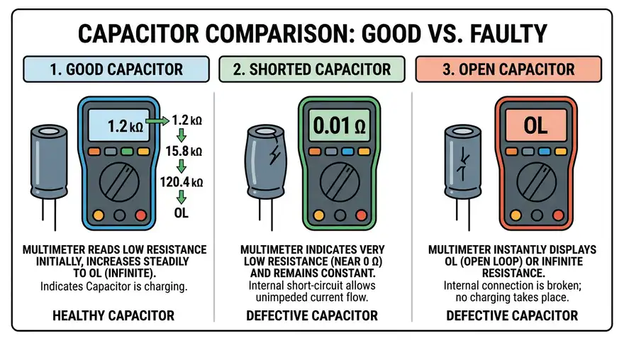
6.2 How to Interpret the Results
Good Capacitor: The resistance reading will start low (near zero ohms) and gradually increase toward infinity (OL). This happens because the multimeter’s internal battery is charging the capacitor through the test leads. As the capacitor charges, less current flows, and the apparent resistance increases. This charging behavior confirms that the capacitor can store charge.
Shorted Capacitor: The resistance stays at zero ohms or a very low value and does not increase. This means the dielectric has failed and the capacitor is conducting directly.
Open Capacitor: The multimeter shows “OL” (open loop) immediately without any initial low reading. The capacitor cannot accept charge, indicating an internal open circuit.
6.3 Practical Example
You are repairing a CRT monitor power supply board and suspect a 470 µF, 25V electrolytic capacitor. You remove the capacitor, discharge it, and set your multimeter to the 200 kΩ range. Upon connecting the leads, the display initially shows around 500 Ω, then slowly climbs to 150 kΩ, and eventually reaches OL. This behavior indicates the capacitor is healthy.
You then test another 470 µF capacitor from the same board. The display shows OL immediately without any initial low reading. This capacitor has an open circuit fault and needs replacement.
7. Method 3: Testing a Capacitor Using Continuity Mode
The continuity mode on a multimeter can also help perform a quick check on a capacitor. This is the simplest test and provides a basic pass/fail result.
7.1 Step-by-Step Procedure
Step 1: Remove and discharge the capacitor.
Step 2: Set your multimeter to continuity mode (indicated by a diode or speaker symbol).
Step 3: Touch the test leads to the capacitor terminals.
Step 4: Listen for the beep and observe the display.
7.2 How to Interpret the Results
Good Capacitor: The multimeter may beep briefly and then stop beeping. The brief beep occurs because the discharged capacitor initially draws current (appearing as a short circuit momentarily), then the current decreases as the capacitor charges.
Shorted Capacitor: The multimeter beeps continuously. This confirms a short circuit inside the capacitor.
Open Capacitor: The multimeter does not beep at all, and the display shows OL throughout. The capacitor has no continuity and cannot pass current even momentarily.
This test method is quick but limited. It cannot tell you the capacitance value or whether the capacitance has degraded. Use this method only for quick go/no-go checks during field troubleshooting.
8. Testing Different Types of Capacitors
Different capacitor types require slightly different testing considerations. Here is a breakdown by capacitor type.
8.1 Electrolytic Capacitors
Electrolytic capacitors are polarized. Always connect the red lead to the positive terminal (marked with a stripe indicating the negative side, or a “+” mark for positive). These capacitors are the most likely to fail because they contain liquid or polymer electrolyte that degrades over time. All three multimeter test methods work well on electrolytic capacitors due to their relatively large capacitance values.
Look for physical signs of failure such as bulging tops, leaking electrolyte, or burn marks. A visually damaged electrolytic capacitor should be replaced immediately without further testing.
8.2 Ceramic Capacitors
Ceramic capacitors are non-polarized and come in very small capacitance values, often in the picofarad (pF) to low microfarad (µF) range. The resistance method is generally not effective for ceramic capacitors because they charge too quickly for the multimeter to register a change. Use the capacitance mode for accurate testing of ceramic capacitors.
8.3 Film Capacitors
Film capacitors are also non-polarized and are commonly found in audio circuits, power electronics, and filtering applications. They are generally more reliable than electrolytic capacitors but can still fail due to overvoltage or physical damage. The capacitance mode provides the best results for film capacitors.
8.4 Tantalum Capacitors
Tantalum capacitors are polarized and can fail catastrophically if subjected to overvoltage or reverse polarity. They can short circuit and even catch fire. Handle these with care. Test them the same way as electrolytic capacitors, but pay close attention to polarity.
8.5 Motor Run and Motor Start Capacitors
Motor capacitors are commonly rated in the range of 5 µF to 400 µF and are used in single-phase AC motors. Motor start capacitors are designed for intermittent duty, and motor run capacitors are designed for continuous duty. Both types can be tested using the capacitance mode. A motor run capacitor should measure within ±5% to ±10% of its rated value for proper motor operation. Per NEMA MG-1 standards, a capacitor that has lost more than 10% of its rated capacitance should be replaced.
9. Testing a Capacitor In-Circuit vs. Out-of-Circuit
Testing a capacitor while it is still soldered into a circuit board is called in-circuit testing. Testing after removing it from the circuit is called out-of-circuit testing.
Out-of-Circuit Testing is always preferred because it eliminates interference from other components. Resistors, inductors, and other capacitors connected in parallel can alter the readings and give false results.
In-Circuit Testing can be useful for a quick preliminary check, but the results should not be considered definitive. If an in-circuit test suggests a fault, remove the capacitor and test it again out-of-circuit for confirmation.
For accurate in-circuit capacitor testing, specialized tools like an ESR meter or an LCR meter are more appropriate than a standard multimeter. These instruments use AC signals to measure the capacitor’s impedance at specific frequencies, which helps isolate the capacitor from surrounding circuit elements.
10. Capacitor Ratings and Markings
To test a capacitor accurately, you need to know its rated capacitance and voltage. This information is printed on the capacitor body.
Electrolytic capacitors usually have the capacitance value in microfarads (µF), the voltage rating in volts (V), and the temperature rating in degrees Celsius printed directly on the case. For example, “100µF 25V 105°C.”
Ceramic capacitors use a three-digit code. The first two digits are the value, and the third digit is the multiplier (number of zeros). The result is in picofarads. For example, a marking of “104” means 10 × 10,000 = 100,000 pF = 100 nF = 0.1 µF.
Film capacitors often use the same three-digit code or print the value directly in microfarads or nanofarads.
11. Common Mistakes to Avoid
Here are some frequent mistakes that people make during capacitor testing:
Not discharging the capacitor before testing. A charged capacitor can damage your multimeter or give you an electric shock. Always discharge first.
Testing in-circuit and trusting the reading completely. Parallel components will skew the results. Remove the capacitor for accurate measurement.
Using the wrong multimeter range. If you are measuring a 10 µF capacitor but your multimeter is set to the nF range, you may get an overload reading. Select the appropriate range or use auto-range mode.
Ignoring polarity on polarized capacitors. Connecting a polarized capacitor backwards during testing usually does not cause damage at the low voltage provided by a multimeter battery. However, it is good practice to observe correct polarity at all times.
Assuming a capacitor is good based on appearance alone. Many failed capacitors look perfectly normal externally. Always perform electrical testing to confirm functionality.
12. Relevant Industry Standards
Several industry standards govern capacitor testing, rating, and safety. Here are some of the most relevant ones:
- ANSI/EIA-198: Standard for ceramic dielectric capacitors
- IEC 60384: Fixed capacitors for use in electronic equipment
- IEC 61071: Capacitors for power electronics
- NEMA MG-1: Motors and generators, including specifications for motor capacitors
- ANSI C37.99: Guide for the protection of shunt capacitor banks
- UL 810: Standard for capacitors
These standards define testing methods, acceptable tolerance ranges, voltage derating guidelines, and safety requirements. Following these standards is necessary for professional applications in power systems, industrial controls, and consumer electronics.
13. Conclusion
Testing a capacitor with a multimeter is a straightforward process that requires only basic equipment and knowledge. The three primary methods — capacitance mode, resistance mode, and continuity mode — each serve a purpose depending on the tools available and the level of detail needed. Capacitance mode gives you an actual value to compare against the rated specification. Resistance mode allows you to observe charging behavior and detect shorts or opens. Continuity mode provides a quick pass/fail check.
Always prioritize safety by disconnecting power, discharging the capacitor fully, and wearing appropriate PPE. Remove the capacitor from the circuit for the most accurate measurements. Compare your readings against the manufacturer’s rated values and applicable industry standards such as IEC 60384 and NEMA MG-1.
14. Frequently Asked Questions (FAQs)
You can perform a quick check in-circuit using the resistance method, but the results may not be accurate. Other components in the circuit can affect the reading. For reliable results, always remove the capacitor from the circuit before testing.
A good capacitor should show a low resistance initially that gradually increases toward infinity (OL). This indicates that the capacitor is accepting and holding charge. A steady zero reading means it is shorted, and an immediate OL reading means it is open.
Most digital multimeters with capacitance mode can measure values from a few picofarads to several millifarads with reasonable accuracy (±1% to ±5%). For high-precision measurements, a dedicated LCR meter is recommended.
Connect a resistor across the capacitor terminals. A 1 kΩ to 10 kΩ resistor rated for the appropriate wattage works for most applications. Wait until the voltage across the terminals reads 0V on your multimeter.
OL stands for “overload” or “open loop.” In capacitance mode, OL usually means the capacitor is open-circuited. In resistance mode, OL means the resistance is higher than the selected range, which could indicate a fully charged capacitor or an open capacitor.
Yes. Use the capacitance mode to measure the actual value and compare it with the rated value printed on the capacitor. Motor start capacitors that have lost more than 10% of their rated capacitance should be replaced.
Follow the maintenance schedule recommended by the equipment manufacturer. In general, capacitors in HVAC systems, motor control centers, and power factor correction panels should be tested annually as part of preventive maintenance programs.
A charged capacitor can damage a multimeter if you attempt to measure resistance or capacitance without discharging it first. The stored energy can exceed the input protection rating of the meter and cause permanent damage.