Every electrical circuit needs a source of energy to function. Voltage sources and current sources are the two fundamental building blocks that power all electrical circuits. These sources provide the electromotive force and current required to drive electrons through conductors and components. In the real world, no source behaves perfectly. However, engineers and students rely on ideal source models to simplify circuit analysis and build a strong theoretical foundation.
Ideal voltage and current sources are theoretical constructs used in circuit theory, network analysis, and electrical engineering education. They form the basis for advanced concepts such as Thévenin and Norton equivalent circuits, source transformation, superposition theorem, and nodal and mesh analysis methods. A solid grasp of these concepts is necessary for anyone pursuing electrical engineering or electronics design professionally.
In this technical guide, we will discuss everything you need to know about ideal voltage and current sources, including their definitions, characteristics, V-I curves, mathematical representations, differences from practical sources, short circuit and open circuit behavior, practical applications, and reasons why ideal sources cannot exist physically. Practical examples are included throughout to help you apply these concepts in real-world scenarios confidently.
1. What is a Source in Electrical Engineering?
A source in electrical engineering is a device or system that converts one form of energy into electrical energy. The input energy can be mechanical, chemical, thermal, solar, or any other form. The source then delivers this converted electrical energy to the circuit it is connected to.
For example, a battery converts chemical energy into electrical energy. A solar panel converts light energy into electrical energy. A generator converts mechanical energy into electrical energy. All of these are sources because they supply the electrical energy that powers circuit components.
Sources serve as the starting point of any electrical system. Without a source, no current can flow and no work can be done in the circuit. Every circuit analysis problem begins with identifying the sources and their types.
2. Types of Sources in Electrical Circuits
There are two main categories of sources based on their output behavior.
Independent Sources: These sources deliver a fixed output regardless of other circuit variables. They are not influenced by voltages or currents elsewhere in the circuit. Independent voltage sources and independent current sources fall into this category.
Dependent (Controlled) Sources: These sources have outputs that depend on a voltage or current somewhere else in the circuit. There are four types of dependent sources: voltage-controlled voltage source (VCVS), current-controlled voltage source (CCVS), voltage-controlled current source (VCCS), and current-controlled current source (CCCS). Dependent sources are beyond the scope of this article and will be covered separately.
Among independent sources, there are two fundamental types based on what quantity they maintain constant.
- Current Sources — maintain a specified current through their terminals
- Voltage Sources — maintain a specified voltage across their terminals
3. What is a Voltage Source?
A voltage source is a two-terminal device or component in an electric circuit that provides electrical energy by maintaining a specific potential difference across its terminals. The voltage source establishes an electromotive force (EMF) that drives current through the circuit.
Real-world examples of voltage sources include batteries, DC power supplies, AC generators, and alternators. Each of these devices maintains a relatively stable voltage output under normal operating conditions.
3.1 What is an Ideal Voltage Source?
An ideal voltage source is a two-terminal electrical device that maintains a constant voltage across its terminals regardless of the current flowing through it. This is a purely theoretical component. It can supply any amount of current demanded by the load without any change in its terminal voltage.

The characteristics of an ideal voltage source are listed below.
- Zero Internal Resistance: An ideal voltage source has absolutely no internal resistance. There is no voltage drop inside the source itself. All the generated EMF appears directly across the terminals.
- Constant Terminal Voltage: The voltage across the output terminals stays fixed at the rated value. It does not change with variations in load resistance or load current. A 12V ideal voltage source will always deliver exactly 12V at its terminals.
- No Limit on Current Output: The source delivers whatever current the connected load demands. If the load resistance decreases, the current increases proportionally. There is no maximum current rating for an ideal voltage source.
- No Internal Power Dissipation: Because the internal resistance is zero, no power is wasted inside the source. All the power generated is delivered to the external circuit completely.
3.2 Mathematical Representation of Ideal Voltage Source
Consider an ideal voltage source with EMF \(V_s\) connected to a load resistance \(R_L\).
The terminal voltage equals the source voltage at all times:
\(V_{terminal}=V_s\)
The current through the circuit is determined by Ohm’s law:
\(I=\dfrac{V_s}{R_L}\)
Here, \(V_{terminal}\) is the voltage measured across the load terminals. It equals the source voltage exactly because there is no internal resistance to cause any voltage drop.
Example: An ideal voltage source of 24V is connected to a 6Ω load resistor. The terminal voltage is 24V. The current through the circuit is \(I=\dfrac{24}{6}=4A\). If the load resistance changes to 3Ω, the terminal voltage remains 24V and the current becomes \(I=\dfrac{24}{3}=8A\). The voltage stays constant regardless of the load change.
3.3 V-I Characteristics of an Ideal Voltage Source
The voltage-current (V-I) characteristic curve of an ideal voltage source is a horizontal straight line on a graph where the X-axis represents current and the Y-axis represents voltage.

This horizontal line indicates that the voltage remains at a fixed value no matter how much current the source delivers. At zero current (open circuit), the voltage is \(V_s\). At very high current, the voltage is still \(V_s\). The line never slopes downward.
This behavior is what makes it “ideal.” A practical voltage source would show a slightly downward-sloping line because its terminal voltage decreases as current increases due to internal resistance.
4. What is a Current Source?
A current source is a two-terminal device or component in an electric circuit that delivers a specified current to the circuit regardless of the voltage across its terminals. The current source adjusts its terminal voltage as needed to maintain constant current flow through the load.
Current sources appear frequently in transistor biasing circuits, LED driver circuits, and electronic instrumentation. They are less intuitive than voltage sources for beginners, but they are equally important in circuit analysis.
4.1 What is an Ideal Current Source?
An ideal current source is a two-terminal device that maintains a constant current flow through its terminals regardless of the voltage that develops across them. This is also a purely theoretical component. It can develop any amount of voltage across its terminals to maintain the specified current output.

The characteristics of an ideal current source are listed below.
- Infinite Internal Resistance: An ideal current source has infinite internal resistance. This means no current is diverted internally. All of the generated current flows through the external load circuit entirely.
- Constant Output Current: The current delivered by the source remains fixed at its rated value. It does not change regardless of changes in load resistance or terminal voltage. A 5A ideal current source will always deliver exactly 5A.
- No Limit on Terminal Voltage: The source develops whatever voltage is necessary across its terminals to push the rated current through the load. There is no maximum voltage rating for an ideal current source.
- No Internal Power Dissipation: Because the internal resistance is infinite and in parallel, no current flows through it. All the source current is delivered to the load without any internal losses.
4.2 Mathematical Representation of an Ideal Current Source
Consider an ideal current source with rated current \(I_s\) connected to a load resistance \(R_L\). The governing equations are as follows.
The output current equals the source current at all times:
\(I_{output}=I_s\)
The terminal voltage adjusts according to Ohm’s law:
\(V_{terminal}=I_s\times R_L\)
The current stays constant. The terminal voltage changes proportionally with load resistance.
Example: An ideal current source of 3A is connected to a 10Ω load resistor. The output current is 3A. The terminal voltage is \(V=3\times 10=30V\). If the load resistance changes to 20Ω, the current remains 3A and the terminal voltage becomes \(V=3\times 20=60V\). The current stays constant while the voltage adjusts automatically.
4.3 V-I Characteristics of an Ideal Current Source
The voltage-current (V-I) characteristic curve of an ideal current source is a vertical straight line on a graph where the X-axis represents voltage and the Y-axis represents current.

This vertical line indicates that the current remains at a fixed value no matter what voltage appears across the source terminals. At zero voltage (short circuit), the current is \(I_s\). At very high voltage, the current is still \(I_s\). The line never shifts horizontally.
This behavior is the defining feature of an ideal current source. A practical current source would show a slight deviation from the vertical line because its output current decreases somewhat as terminal voltage increases.
5. Combined V-I Characteristics of Voltage and Current Sources
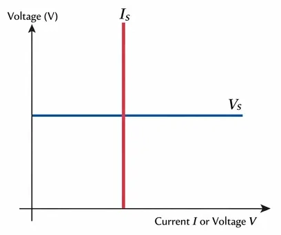
Placing both characteristic curves on a single graph makes the contrast very clear. The ideal voltage source curve is a horizontal line (constant voltage, variable current). The ideal current source curve is a vertical line (constant current, variable voltage). These two behaviors are fundamentally opposite and complementary. This duality is the basis for source transformation techniques used in circuit analysis.
6. Differences Between Ideal and Practical Voltage Sources
| Aspect | Ideal Voltage Source | Practical Voltage Source |
|---|---|---|
| Definition | Maintains constant voltage regardless of current drawn | Provides nearly constant voltage but is affected by internal resistance |
| Internal Resistance | Zero | Small but non-zero, connected in series with the source |
| Terminal Voltage Behavior | Voltage remains fixed under all load conditions | Voltage decreases as load current increases |
| Current Supply | Can provide unlimited current | Limited by internal resistance and source capacity |
| Voltage Regulation | Perfect voltage regulation under all conditions | Voltage output drops under heavy load conditions |
| Power Dissipation | No internal power dissipation | Some power is lost as heat in the internal resistance |
6.1 Practical Voltage Source Equation
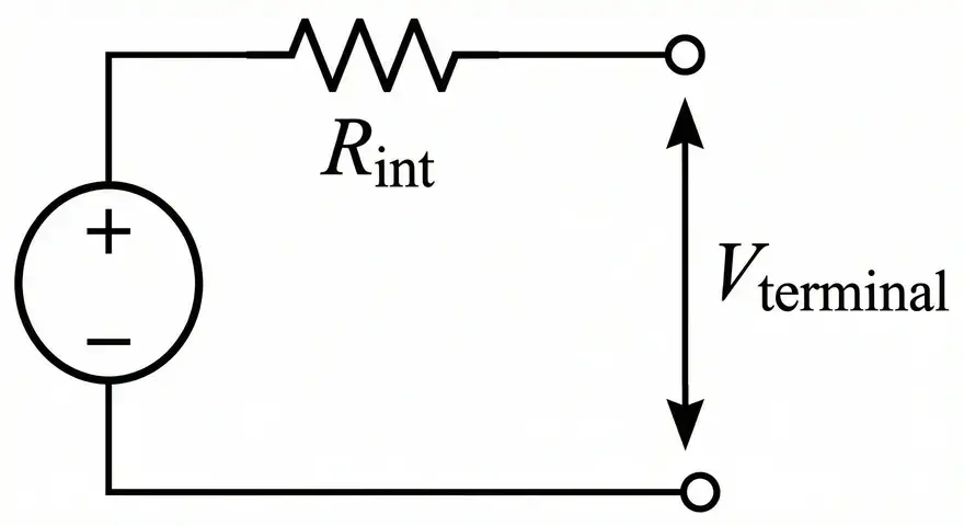
A practical voltage source is modeled as an ideal voltage source in series with an internal resistance \(R_{int}\). The terminal voltage equation is:
\(V_{terminal}=V_{source}−I\times R_{int}\)
As current \(I\) increases, the voltage drop across \(R_{int}\) increases, and the terminal voltage decreases accordingly.
Example: A practical battery has an EMF of 12V and an internal resistance of 0.2Ω. If the load draws 5A, the terminal voltage is \(V=12−5\times 0.2=12−1=11V\). The 1V drop occurs inside the battery due to its internal resistance.
7. Differences Between Ideal and Practical Current Sources
| Aspect | Ideal Current Source | Practical Current Source |
|---|---|---|
| Definition | Maintains constant current regardless of terminal voltage | Provides nearly constant current but is affected by internal resistance |
| Internal Resistance | Infinite | Large but finite, connected in parallel with the source |
| Output Current Behavior | Current remains fixed under all load conditions | Current decreases slightly as load resistance increases |
| Voltage Supply | Can develop unlimited voltage | Limited by the source’s maximum voltage capability |
| Current Regulation | Perfect current regulation under all conditions | Current output varies slightly due to practical limitations |
| Power Dissipation | No internal power dissipation | Some current leaks through the parallel internal resistance |
7.1 Practical Current Source Equation
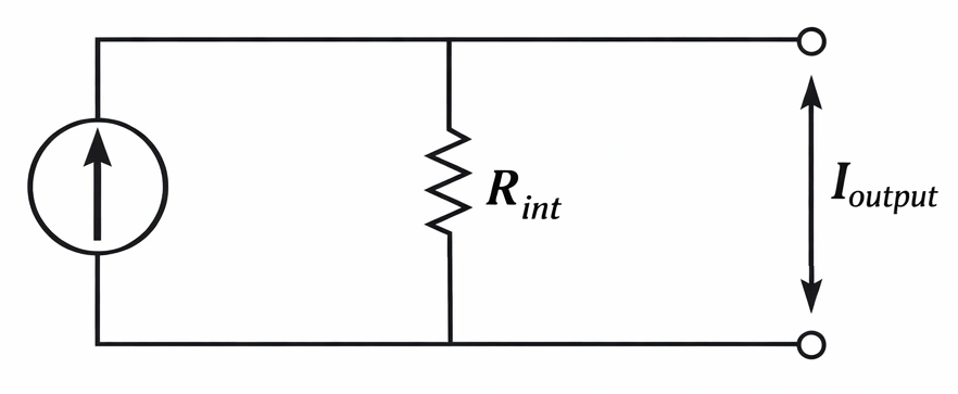
A practical current source is modeled as an ideal current source in parallel with an internal resistance \(R_{int}\). The output current equation is:
\(I_{output}=I_s−\dfrac{V_{terminal}}{R_{int}}\)
As the terminal voltage \(V_{terminal}\) increases, more current leaks through the parallel internal resistance, and the output current delivered to the load decreases.
Example: A practical current source has a rated current of 5A and an internal parallel resistance of 500Ω. If the terminal voltage is 50V, the output current is \(I=5−\dfrac{50}{500}=5−0.1=4.9A\). A small portion of the source current is lost through the internal resistance.
8. Comparison Between Ideal Voltage and Ideal Current Sources
| Parameter | Ideal Voltage Source | Ideal Current Source |
|---|---|---|
| Maintained Quantity | Constant voltage | Constant current |
| Variable Quantity | Current (determined by load) | Voltage (determined by load) |
| Internal Resistance | Zero | Infinite |
| V-I Curve Shape | Horizontal line | Vertical line |
| Circuit Symbol | Circle with + and – signs | Circle with arrow |
| Short Circuit Behavior | Maintains rated voltage; current approaches infinity | Maintains rated current; voltage drops to zero |
| Open Circuit Behavior | Maintains rated voltage; current equals zero | Maintains rated current; voltage approaches infinity |
| Dangerous Condition | Short circuit (infinite current, infinite power) | Open circuit (infinite voltage, infinite power) |
9. Behavior of Ideal Sources Under Short Circuit and Open Circuit Conditions
9.1 Ideal Voltage Source in Short Circuit
A short circuit means the load resistance is zero. The ideal voltage source maintains its rated voltage \(V_s\). The current becomes \(I=\dfrac{V_s}{0}=\infty\). The power delivered becomes infinite. This is a physically impossible condition, which is one reason why ideal voltage sources cannot exist.
9.2 Ideal Current Source in Short Circuit
A short circuit across an ideal current source means zero load resistance. The source maintains its rated current \(I_s\). The terminal voltage becomes \(V=I_s\times 0=0V\). The power delivered is zero. This is a perfectly valid and non-destructive condition for an ideal current source.
9.3 Ideal Voltage Source in Open Circuit
An open circuit means the load resistance is infinite. The ideal voltage source maintains its rated voltage \(V_s\). The current is \(I=\dfrac{V_s}{\infty}=0A\). The power delivered is zero. This is a perfectly valid condition for an ideal voltage source.
9.4 Ideal Current Source in Open Circuit
An open circuit across an ideal current source means infinite load resistance. The source maintains its rated current \(I_s\). The terminal voltage becomes \(V=I_s\times \infty=\infty\). The power becomes infinite. This is a physically impossible condition and is one reason why ideal current sources cannot exist.
Notice the symmetry here. The dangerous condition for an ideal voltage source is a short circuit. The dangerous condition for an ideal current source is an open circuit. These are dual conditions.
10. Why Ideal Sources Cannot Exist Physically
Ideal voltage and current sources are mathematical models only. They cannot be built or found in nature for several fundamental reasons.
10.1 Infinite Power Requirement
An ideal voltage source connected to a short circuit would need to deliver infinite power. An ideal current source connected to an open circuit would also need to deliver infinite power. No physical device can generate unlimited power.
10.2 Material Limitations
Creating a voltage source with absolutely zero internal resistance is physically impossible. All conductors and materials have some resistance, no matter how small. Similarly, creating a current source with truly infinite internal resistance is impossible because all insulators have finite resistance values.
10.3 Contradictions in Circuit Configurations
Connecting two ideal voltage sources with different voltage ratings in parallel creates a logical paradox. According to Kirchhoff’s Voltage Law (KVL), both sources must have the same terminal voltage, but they are rated differently. This creates an undefined condition. Similarly, connecting two ideal current sources with different current ratings in series violates Kirchhoff’s Current Law (KCL) and creates another paradox.
10.4 Energy Conservation Violations
Under extreme loading conditions, ideal sources would violate the law of conservation of energy by producing energy from nothing. No real device can do this.
11. Practical Applications of Voltage Sources
Many real-world devices approximate ideal voltage source behavior under normal operating conditions.
11.1 Batteries and Battery Banks
Lead-acid batteries, lithium-ion cells, nickel-metal hydride cells, and other battery technologies maintain relatively stable terminal voltage across their normal discharge range. Their internal resistance is small, making them good approximations of voltage sources for most applications. Battery bank design for solar power systems and uninterruptible power supplies (UPS) relies heavily on voltage source modeling.
11.2 Regulated DC Power Supplies
Laboratory DC power supplies and switch-mode power supplies (SMPS) use feedback regulation circuits to maintain constant output voltage. These devices come very close to ideal voltage source behavior within their rated current range. Electrical engineering students use these power supplies regularly in lab experiments.
11.3 Electrical Generators and Alternators
AC generators in power plants and alternators in vehicles function as voltage sources. They maintain consistent voltage levels through automatic voltage regulators (AVR). Power grid voltage regulation depends on these devices operating as stable voltage sources.
11.4 Solar Inverters (Output Stage)
Grid-tied solar inverters convert DC from solar panels into AC voltage that matches the grid voltage. The output stage behaves as a voltage source synchronized with the utility grid.
12. Practical Applications of Current Sources
Current sources appear in many electronic and electrical applications. Some devices naturally behave as current sources.
12.1 Solar Photovoltaic Cells
Solar panels approximate current source behavior over a large portion of their operating range. The photovoltaic effect generates electron-hole pairs that produce a relatively constant current under fixed illumination. The current output depends primarily on light intensity rather than load voltage. This current source behavior holds true below the maximum power point on the solar cell’s I-V curve. Solar panel installation and design engineers account for this current source characteristic during system sizing.
12.2 LED Driver Circuits
LEDs require constant current for proper operation and longevity. LED driver circuits are designed as constant current sources that maintain a fixed current through the LED regardless of voltage variations. Constant current LED drivers are used extensively in automotive lighting, street lighting, and commercial lighting systems.
12.3 Transistor Current Sources and Current Mirrors
Bipolar junction transistors (BJTs) and MOSFETs are configured as current sources in analog circuit design. Current mirror circuits provide matched constant currents to multiple branches of an integrated circuit. These configurations are fundamental to operational amplifier (op-amp) design and analog IC design.
12.4 Current Transformers
Used in power system protection and measurement, current transformers produce a secondary current that is proportional to the primary current. They behave as current sources regardless of the secondary burden (load impedance). Power system engineers and relay protection specialists work with current transformers daily.
13. Source Transformation: Connecting Voltage and Current Source Concepts
Source transformation is a circuit analysis technique that allows you to convert a voltage source with a series resistance into an equivalent current source with a parallel resistance, and vice versa.
13.1 Voltage Source to Current Source
A voltage source \(V_s\) in series with resistance \(R_s\) can be replaced by a current source \(I_s=\dfrac{V_s}{R_s}\) in parallel with the same resistance \(R_s\).
13.2 Current Source to Voltage Source
A current source \(I_s\) in parallel with resistance \(R_s\) can be replaced by a voltage source \(V_s=I_s\times R_s\) in series with the same resistance \(R_s\).
This transformation works because both configurations produce identical voltage and current at the output terminals for any connected load. Source transformation is used in Thévenin and Norton equivalent circuit analysis. It simplifies complex networks by converting between source types as needed.
Note: Source transformation only applies to practical sources (with finite internal resistance). An ideal voltage source (zero internal resistance) cannot be converted to a current source, and an ideal current source (infinite internal resistance) cannot be converted to a voltage source.
14. Conclusion
Ideal voltage and current sources are foundational concepts in electrical circuit theory. An ideal voltage source maintains constant terminal voltage with zero internal resistance. An ideal current source maintains constant output current with infinite internal resistance. These models do not exist in the physical world because they would require infinite power under extreme conditions. However, they serve as indispensable tools for circuit analysis, network theorems, and electrical system design.
15. Frequently Asked Questions (FAQs)
An ideal voltage source maintains a constant voltage across its terminals regardless of the current flowing through it. It has zero internal resistance. An ideal current source maintains a constant current through its terminals regardless of the voltage across them. It has infinite internal resistance. The V-I curve for an ideal voltage source is a horizontal line, and for an ideal current source, it is a vertical line.
No. An ideal voltage source cannot exist in real life because it would need to supply infinite current under short circuit conditions. This would require infinite power, which violates the laws of physics.
If you short-circuit an ideal voltage source, the current becomes theoretically infinite because the load resistance is zero and the source has zero internal resistance. This condition is physically impossible and would require infinite power.
If you open-circuit an ideal current source, the terminal voltage becomes theoretically infinite because the source tries to push its rated current through infinite resistance. This condition is physically impossible and would require infinite power.
An ideal voltage source has zero internal resistance so that no voltage is dropped inside the source. This ensures that the full EMF appears across the output terminals regardless of the current drawn.
An ideal current source has infinite internal resistance (in parallel) so that no current leaks through the internal path. All the generated current flows through the external load. Infinite parallel resistance forces the entire source current into the load circuit.
A practical voltage source has a small but non-zero internal resistance connected in series with the ideal EMF. This resistance causes the terminal voltage to drop as load current increases. For example, a AA battery has an internal resistance of about 0.1Ω to 0.3Ω.
Current sources are used in LED driver circuits, transistor biasing circuits, current mirrors in integrated circuits, current transformers in power systems, and solar photovoltaic cells.
No. Connecting two ideal voltage sources with different voltage ratings in parallel creates a contradiction of Kirchhoff’s Voltage Law. Both sources would try to impose different voltages on the same pair of nodes, which is physically impossible. This would result in theoretically infinite circulating current.