In AC circuits, the relationship between voltage and current is not always straightforward. Unlike DC circuits where resistance is the only opposition to current flow, AC circuits involve a combination of resistance, inductance, and capacitance. This combination creates a quantity called impedance. Impedance has both magnitude and direction, making it a vector quantity. The direction of this vector is described by the impedance angle.
The impedance angle tells us how much the current leads or lags behind the voltage in an AC circuit. It is one of the most fundamental concepts in AC circuit analysis. Engineers use it daily in power system design, motor control, transmission line analysis, and protective relay settings.
In this technical guide, we will discuss everything you need to know about impedance angle, including its definition, mathematical derivation, relationship with power factor, role in AC circuit analysis, practical applications, and relevant industry standards. Practical examples are included throughout to help you apply these concepts in real-world scenarios confidently.
1. What is Impedance Angle?
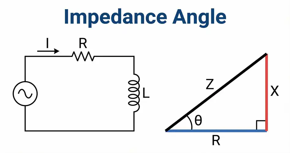
The impedance angle is the phase angle of the total impedance in an AC circuit. It is the angle between the resistance component and the total impedance vector in an impedance triangle. This angle is measured in degrees or radians.
In mathematical terms, impedance (Z) is a complex quantity expressed as:
\(Z = R + jX\)
Here, R is the resistance (real part) and X is the reactance (imaginary part). The impedance angle \((\theta \text{ or } \phi)\) is calculated as:
\(\theta = \arctan \left(\dfrac{X}{R}\right)\)
The impedance angle determines the phase difference between the voltage across the circuit and the current flowing through it. If the angle is positive, the circuit is inductive, and the current lags the voltage. If the angle is negative, the circuit is capacitive, and the current leads the voltage. If the angle is zero, the circuit is purely resistive, and voltage and current are in phase.
2. The Impedance Triangle
The impedance triangle is a right-angle triangle that visually shows the relationship between resistance, reactance, and impedance. The horizontal side of the triangle is the resistance (R). The vertical side is the reactance (X). The hypotenuse is the total impedance (Z).
The impedance angle is the angle between the resistance (horizontal side) and the impedance (hypotenuse). This triangle is a direct graphical tool for calculating the impedance angle.
Magnitude of impedance:
\(|Z| = \sqrt{(R^2 + X^2)}\)
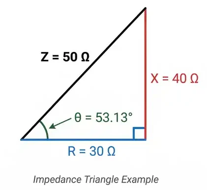
For example, consider a series RL circuit with \(R = 30 Ω\) and inductive reactance \(X_L = 40 Ω\).
\(|Z| = \sqrt{(30^2 + 40^2)} = \sqrt{(900 + 1600)} = \sqrt{2500} = 50 Ω\)
\(\theta = \arctan \left(\dfrac{40}{30}\right) = \arctan(1.333) = 53.13°\)
The impedance angle is 53.13°, meaning the current lags the voltage by 53.13 degrees. This is an inductive circuit.
3. Impedance Angle in Different Types of AC Circuits
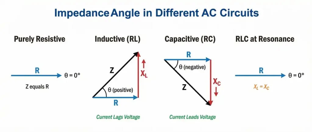
3.1 Purely Resistive Circuit
In a purely resistive circuit, there is no reactance. \(X = 0\), so the impedance angle is:
\(\theta = \arctan\left(\dfrac{0}{R}\right) = 0°\)
Voltage and current are perfectly in phase. All power delivered is real power. This is the ideal condition for resistive heating elements and incandescent lamps.
3.2 Purely Inductive Circuit
In a purely inductive circuit, there is no resistance. \(R = 0\), and the reactance is entirely inductive \((X_L > 0)\). The impedance angle is:
\(\theta = \arctan\left(\dfrac{X_L}{0}\right) = 90°\)
The current lags the voltage by 90 degrees. No real power is consumed. All power is reactive. This is a theoretical condition, as all real inductors have some resistance.
3.3 Purely Capacitive Circuit
In a purely capacitive circuit, there is no resistance. \(R = 0\), and the reactance is entirely capacitive \((X_C < 0)\). The impedance angle is:
\(\theta = \arctan\left(\dfrac{-X_C}{0}\right)= −90°\)
The current leads the voltage by 90 degrees. Again, no real power is consumed.
3.4 Series RLC Circuit
In a series RLC circuit, both inductive and capacitive reactances are present. The net reactance is:
\(X = X_L − X_C\)
If \(X_L > X_C\), the circuit behaves inductively, and \(\theta\) is positive.
If \(X_C > X_L\), the circuit behaves capacitively, and \(\theta\) is negative.
If \(X_L = X_C\), the circuit is at resonance, and \(\theta = 0°\).
4. Impedance Angle and Power Factor
The impedance angle has a direct mathematical relationship with power factor. Power factor (PF) is defined as:
\(\text{PF} = \cos(\theta)\)
Here, \(\theta\) is the impedance angle. A power factor of 1 (unity) means the impedance angle is \(0°\), and all power is real power. A power factor of 0 means the impedance angle is \(90°\) (or \(−90°\)), and all power is reactive.
4.1 Practical Example
A factory has a load with an impedance angle of 36.87°. The power factor is:
\(\text{PF} = \cos(36.87°) = 0.8 \text{lagging}\)
This means only 80% of the apparent power is being used as real power. The remaining 20% is reactive power. This lagging power factor is common in industrial facilities with large induction motors.
Electric utilities charge penalties for low power factor because it increases the current demand on the system without delivering useful work. Power factor correction capacitors are installed to reduce the impedance angle and bring the power factor closer to unity.
5. Role of Impedance Angle in Power Calculations
The impedance angle plays a direct role in calculating the three types of power in AC circuits.
Real Power (P):
\(P = V \times I \times \cos(\theta)\) [Watts]
Reactive Power (Q):
\(Q = V \times I \times \sin(\theta)\) [VAR]
Apparent Power (S):
\(S = V \times I\) [VA]
The power triangle mirrors the impedance triangle. The impedance angle \(\theta\) appears in the same position in both triangles.
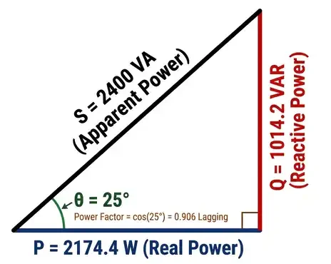
5.1 Example Calculation
A single-phase load draws 10 A from a 240 V supply. The impedance angle is 25°.
\(P = 240 \times 10 \times \cos(25°) = 240 \times 10 \times 0.906 = 2174.4 W\)
\(Q = 240 \times 10 \times \sin(25°) = 240 \times 10 \times 0.4226 = 1014.2 VAR\)
\(S = 240 \times 10 = 2400 VA\)
The real power consumed is 2174.4 W. The reactive power is 1014.2 VAR. The impedance angle of 25° gives a power factor of 0.906 lagging.
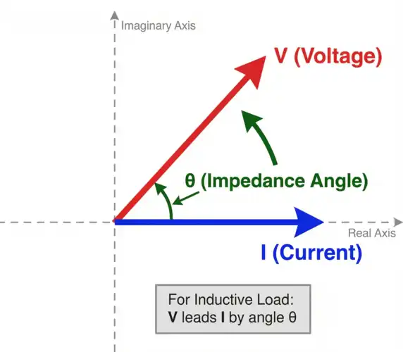
6. Impedance Angle in Phasor Diagrams
Phasor diagrams are graphical tools used to show the magnitude and phase relationships between voltage and current in AC circuits. The impedance angle directly appears in the phasor diagram as the angle between the voltage phasor and the current phasor.
In an inductive circuit, the voltage phasor leads the current phasor by the impedance angle. In a capacitive circuit, the voltage phasor lags the current phasor by the impedance angle. The phasor diagram makes it easy to visualize how the impedance angle affects circuit behavior.
Engineers use phasor diagrams extensively in power system analysis. Protective relay engineers, for instance, plot voltage and current phasors to determine fault types and fault locations. The impedance angle of fault current helps distinguish between resistive faults (like arcing faults) and solid bolted faults.
7. Impedance Angle in Protective Relaying
Protective relays use impedance angle measurements to detect and classify faults in power systems. Distance relays (also called impedance relays) measure the impedance between the relay location and the fault point. The impedance angle of the measured impedance is a defining parameter in relay settings.
7.1 ANSI Code Reference
According to ANSI/IEEE device numbering:
- ANSI Code 21 — Distance Relay (Impedance Relay): This relay operates based on the measured impedance magnitude and angle. The relay’s operating characteristic is plotted on an R-X diagram, where the impedance angle determines the tilt of the relay’s reach characteristic.
- ANSI Code 78 — Out-of-Step Relay: This relay also uses impedance angle measurements to detect power swings and out-of-step conditions in generators and transmission lines.
The Maximum Torque Angle (MTA) of a distance relay is set to match the impedance angle of the protected transmission line. A typical transmission line has an impedance angle between 75° and 85°. The MTA is set accordingly to provide maximum sensitivity for faults along the line.
7.2 Example
A 138 kV transmission line has an impedance of \(Z = 5 + j50 Ω\). The impedance angle is:
\(\theta = \arctan\left(\dfrac{50}{5}\right) = \arctan(10) = 84.3°\)
The distance relay protecting this line would have its MTA set to approximately 84°. This setting allows the relay to accurately measure fault impedance along the line and trip correctly for faults within its protection zone.
8. Impedance Angle in Transmission Line Analysis
Transmission lines have characteristic impedance with a specific impedance angle. This angle depends on the line’s resistance, inductance, and capacitance per unit length.
Short transmission lines are modeled with series impedance only \((R + j\omega L)\). The impedance angle of a short line is:
\(\theta = \arctan\left(\dfrac{\omega L}{R}\right)\)
For high-voltage transmission lines, the inductive reactance is much larger than the resistance. This makes the impedance angle close to 90°. For lower voltage distribution lines, the resistance is more prominent, and the impedance angle is lower (around 30° to 60°).
The impedance angle of a transmission line affects voltage regulation, power transfer capability, and stability limits. Lines with high impedance angles (close to 90°) have better power transfer characteristics because the real power transfer equation is:
\(P = \dfrac{(V_1 \times V_2 \times \sin(\delta))}{X}\)
Here, \(\delta\) is the power angle between the sending and receiving end voltages. The reactive component \((X)\) dominates in lines with high impedance angles, and this equation gives a good approximation of power flow.
9. Impedance Angle in Motor Circuits
Electric motors are inductive loads. They draw current that lags behind the voltage. The impedance angle of a motor circuit changes with loading conditions.
At no-load, an induction motor draws mostly magnetizing current. The impedance angle is high (close to 70°–80°), and the power factor is low (around 0.2–0.3). At full load, the motor draws more real current for mechanical work. The impedance angle decreases (to around 25°–40°), and the power factor improves (to around 0.8–0.9).
9.1 Example
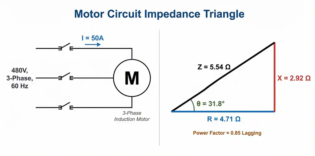
A 480 V, 3-phase induction motor has the following measurements at full load:
- Line current: 50 A
- Power factor: 0.85 lagging
The impedance angle is:
\(\theta = \arccos(0.85) = 31.8°\)
The per-phase impedance magnitude is:
\(|Z| = \dfrac{V_{phase}}{I} = \dfrac{\left(\frac{480}{\sqrt{3}}\right)}{50} = \dfrac{277.1}{50} = 5.54 Ω\)
The resistance and reactance components are:
\(R = Z \times \cos(\theta) = 5.54 \times 0.85 = 4.71 Ω\)
\(X = Z \times \sin(\theta) = 5.54 \times 0.527 = 2.92 Ω\)
This information is useful for motor starting calculations, short-circuit studies, and power factor correction sizing.
10. Impedance Angle at Resonance
Resonance occurs in an RLC circuit when the inductive reactance equals the capacitive reactance \((X_L = X_C)\). At resonance:
\(X = X_L − X_C = 0\)
The impedance angle becomes:
\(\theta = \arctan\left(\dfrac{0}{R}\right) = 0°\)
At resonance, the circuit behaves as a purely resistive circuit. The impedance is at its minimum value (equal to R) in a series RLC circuit. The current is at its maximum. Voltage and current are perfectly in phase.
Resonance has many practical applications. It is used in radio tuning circuits, filter design, and power factor correction. The impedance angle serves as an indicator of how close a circuit is to resonance. As the circuit approaches resonance, the impedance angle approaches zero.
11. How to Measure Impedance Angle
The impedance angle can be measured using several methods:
11.1 Using an Oscilloscope
Connect the oscilloscope to display both voltage and current waveforms simultaneously. Measure the time difference \((\Delta t)\) between the zero crossings of the voltage and current waveforms. Calculate the impedance angle as:
\(\theta = \left(\dfrac{\Delta t}{T}\right) \times 360°\)
Here, \(T\) is the period of the waveform (20 ms for 50 Hz, 16.67 ms for 60 Hz).
11.2 Using a Power Analyzer
Modern power analyzers directly display the phase angle between voltage and current. They also show power factor, real power, reactive power, and apparent power. This is the most accurate method for measuring impedance angle in field conditions.
11.3 Using an LCR Meter
An LCR meter measures impedance magnitude and angle directly at various test frequencies. It is commonly used for component testing in laboratory environments.
11.4 Calculation from Circuit Parameters
If the circuit components are known, the impedance angle can be calculated mathematically using the arctan formula described earlier.
12. Practical Example: Power Factor Correction Using Impedance Angle
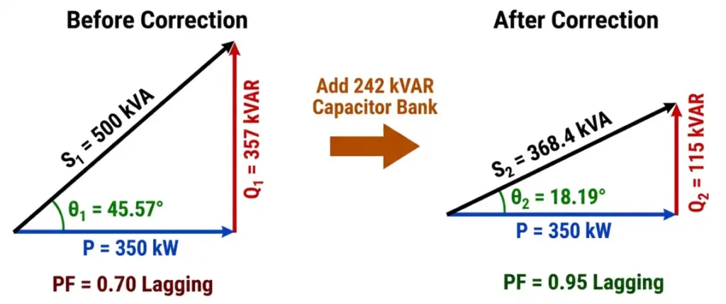
A manufacturing plant has a total load of 500 kVA at a power factor of 0.7 lagging. The plant operates on a 480 V, 3-phase, 60 Hz supply. The utility charges a penalty for power factor below 0.9. The engineer needs to calculate the required capacitor bank size to improve the power factor to 0.95 lagging.
Step 1: Find the original impedance angle.
\(\theta_1 = \arccos(0.7) = 45.57°\)
Step 2: Find the target impedance angle.
\(\theta_2 = \arccos(0.95) = 18.19°\)
Step 3: Calculate original and target reactive power.
\(P = S \times \cos(\theta_1) = 500 \times 0.7 = 350 kW\)
\(Q_1 = S \times \sin(\theta_1) = 500 \times \sin(45.57°) = 500 \times 0.714 = 357 kVAR\)
\(Q_2 = P \times \tan(\theta_2) = 350 \times \tan(18.19°) = 350 \times 0.3287 = 115 kVAR\)
Step 4: Calculate the required capacitor bank size.
\(Q_{cap} = Q_1 − Q_2 = 357 − 115 = 242 kVAR\)
The plant needs a 242 kVAR capacitor bank to change the impedance angle from 45.57° to 18.19°, which improves the power factor from 0.7 to 0.95 lagging.
13. Conclusion
The impedance angle is a foundational concept in AC circuit analysis. It describes the phase relationship between voltage and current in any AC circuit. This single parameter connects impedance, power factor, and power calculations into a unified framework. Engineers use it in circuit design, power system analysis, motor applications, protective relaying, and power factor correction.
A clear knowledge of impedance angle helps in making accurate calculations for real power, reactive power, and apparent power. It also helps in setting protective relays correctly, designing efficient power systems, and avoiding utility power factor penalties. The impedance triangle and phasor diagrams provide simple graphical methods for visualizing and calculating the impedance angle.
14. Frequently Asked Questions (FAQs)
The impedance angle is the phase angle between the voltage and current in an AC circuit. It indicates how much the current leads or lags behind the voltage. A positive angle means the current lags (inductive circuit), and a negative angle means the current leads (capacitive circuit).
The impedance angle is calculated using the formula θ = arctan(X / R), where X is the total reactance and R is the resistance of the circuit. The result is in degrees or radians depending on your calculator setting.
The impedance angle of a purely resistive circuit is 0°. Voltage and current are in phase, and the power factor is unity (1.0).
Power factor equals the cosine of the impedance angle: PF = cos(θ). A smaller impedance angle means a higher power factor. An impedance angle of 0° gives a power factor of 1.0. An impedance angle of 90° gives a power factor of 0.
Distance relays (ANSI Code 21) use the impedance angle to set the Maximum Torque Angle (MTA). This angle must match the impedance angle of the protected transmission line for accurate fault detection and correct relay operation.
No. The impedance angle ranges from −90° (purely capacitive) to +90° (purely inductive). In practical circuits with resistance, the angle is always between −90° and +90°.
Inductive reactance increases with frequency (XL = 2πfL), and capacitive reactance decreases with frequency (XC = 1/2πfC). As frequency changes, the ratio X/R changes, and the impedance angle changes accordingly.
High-voltage transmission lines have impedance angles between 75° and 85° because their inductive reactance is much larger than their resistance. Distribution lines have lower impedance angles, around 30° to 60°.
At resonance, XL = XC, so the net reactance is zero. The impedance angle becomes 0°, and the circuit behaves as a purely resistive circuit.
You can measure impedance angle using a power analyzer, which directly displays the phase angle between voltage and current. An oscilloscope can also be used by measuring the time difference between voltage and current zero crossings.