Transformers are the silent workhorses of power systems. They step voltages up and down, isolate circuits, and enable efficient power distribution across continents. Yet despite their reliability and simplicity, transformers face constant threats from unexpected faults. A sudden short circuit, an insulation breakdown, or a phase-to-ground contact can turn a billion-rupee transformer into scrap metal in seconds. This is where transformer protection becomes necessary.
This technical guide discusses two fundamental protection mechanisms that safeguard transformers from failure: overcurrent protection and earth fault protection.
These are not abstract theoretical concepts, they are practical, proven techniques that electrical engineers implement daily in substations, industrial facilities, and power distribution networks worldwide. Together, these protection methods form a robust shield that detects abnormal current conditions faster than you can blink and isolates faulty equipment before permanent damage occurs.
Transformer Faults and Why Protection is Essential
Transformers, despite being static devices with relatively few moving parts, are vulnerable to various types of faults that can lead to failures if not promptly detected and isolated. The consequences of unprotected transformer faults extend beyond equipment damage, they can cause widespread power outages, fire hazards, and create dangerous conditions for personnel working near electrical installations.
The two primary fault categories that transformer protection systems must address are phase faults (including three-phase and phase-to-phase faults) and earth faults (ground faults or phase-to-ground faults).
Phase faults are characterized by large fault currents that develop when the insulation between phases breaks down, while earth faults occur when phase conductors make contact with grounded equipment or the earth.
The speed of fault detection and isolation is important because transformer windings can sustain significant mechanical and thermal stress during fault conditions. When excessive current flows through transformer windings, it generates heat according to the relationship I²R (where I is current and R is resistance). This heat can rapidly damage insulation materials, leading to winding failure, oil decomposition, and in severe cases, explosion.
Implementing proper overcurrent and earth fault protection, utilities and industrial facilities can minimize exposure time to fault conditions and reduce the likelihood of transformer failure.
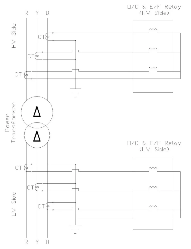
Overcurrent and Earth Fault Relay Wiring Diagram
Overcurrent Protection
Overcurrent protection is the most widely used and fundamental transformer protection method. It operates on a simple principle: if current flowing through the transformer exceeds a predetermined safe level, the protective relay sends a trip signal to the circuit breaker, disconnecting the transformer from the power system.
Pickup Current Setting
The pickup current (also called the threshold current or setting) is the most critical parameter in any overcurrent relay. This value must be set high enough to allow normal operating currents and transient surge currents to pass without nuisance tripping, yet low enough to detect fault conditions promptly.
The full load current of a transformer is calculated using the relationship:
\(I_{rated} = \frac{S_{rated} \times 1000}{\sqrt{3} \times V_{rated}}\)
Where \(S_{rated}\) is the transformer’s rated power in kVA, and \(V_{rated}\) is the rated voltage in volts.
Let’s work through a practical example to illustrate this calculation.
Practical Example: 100 kVA Transformer
Consider a three-phase transformer rated at 100 kVA with a primary voltage of 11 kV and secondary voltage of 440 V. The full load current on the primary side is:
\(I_{rated} = \frac{100 \times 1000}{\sqrt{3} \times 11,000} = \frac{100,000}{19,052} ≈ 5.25 \text{ A}\)
For overcurrent protection, the pickup current should typically be set between 125% to 150% of the full load current to account for normal operating variations and brief transient surge currents. Using 135% as a reasonable middle-ground value:
\(I_{pickup} = 5.25 \times 1.35 = 7.09 \text{ A}\)
This means the overcurrent relay would not operate for currents below approximately 7.1 A, allowing the transformer to carry normal load plus a reasonable safety margin. However, if a fault occurs and the current rises significantly above this threshold, the relay will initiate the protection sequence.
Relay Setting Expressions
When studying overcurrent relay protection, you’ll encounter settings expressed as plug settings and current transformer (CT) ratios. The relationship between these parameters can be confusing for newcomers to the field.
If a 100/5 A current transformer (meaning the primary winding carries 100 A full load and the secondary winding carries 5 A) is installed on the transformer primary, and we desire a 7.09 A pickup on the primary, the secondary current would be:
\(I_{secondary} = \frac{7.09 \times 5}{100} = 0.355 \text{ A}\)
The relay plug setting (expressed as a decimal or fraction of the relay’s base current) would therefore be set to match this secondary current. This indirect method of setting protection levels allows standardized relays with fixed sensitivity to be applied to a wide range of transformer sizes.
Types of Overcurrent Relay Characteristics
Instantaneous Overcurrent Relays (50):
Instantaneous Overcurrent Relays trip immediately when current exceeds the pickup setting, with no intentional time delay. They are typically used as the primary protection on the secondary (low-voltage) side of transformers for fast fault clearing.
Because they lack time delay, they must be coordinated carefully to avoid false operation during inrush currents when the transformer is first energized.
A typical instantaneous relay pickup setting might be set at 130% to 150% of the maximum through-fault current to account for these transient effects.
Inverse Time Overcurrent Relays
Inverse Time Overcurrent Relays employ a time delay that is inversely proportional to the magnitude of the fault current.
In other words, larger fault currents are cleared faster than smaller overcurrents.
This characteristic is extremely valuable for power system coordination because it naturally allows devices closer to a fault to trip first while providing backup protection for upstream devices.
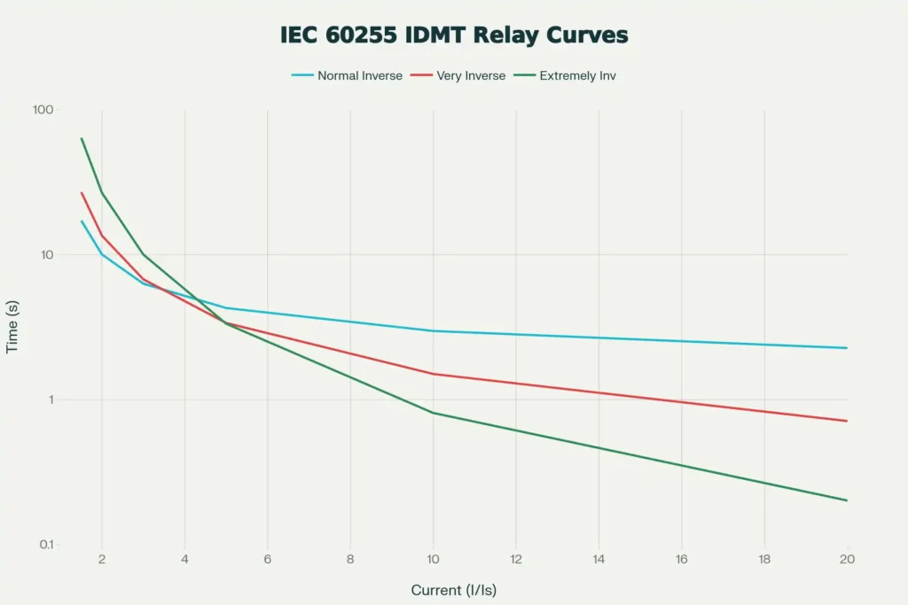
Inverse time relays are offered in three standard varieties based on the degree of “inverseness”:
- Normal Inverse (NI): Provides relatively gradual characteristics, suitable for systems where fault current is somewhat independent of location
- Very Inverse (VI): Offers steeper characteristics, ideal for systems where fault current decreases significantly with distance from the source
- Extremely Inverse (EI): Provides the steepest characteristic, particularly effective for coordinating with ground faults where current magnitude varies considerably with fault location
The operating time for inverse time relays follows the standard equation:
\(t = \frac{T_{MS} \times K}{(I/I_{pickup})^n – 1}\)
Where \(t\) is the operating time in seconds, \(T_{MS}\) is the time multiplier setting, \(K\) and \(n\) are constants dependent on the relay characteristic type, \(I\) is the actual fault current, and \(I_{pickup}\) is the pickup current setting.
Time Multiplier Setting for Coordination
The Time Multiplier Setting (TMS) or Time Dial Setting (TDS) allows engineers to adjust the operating time of a relay without changing its pickup current setting. A TMS of 1.0 represents the standard operating time according to the relay’s characteristic curve. A TMS of 0.5 would operate approximately twice as fast, while a TMS of 2.0 would operate approximately twice as slow.
In transformer protection, the primary-side overcurrent relay typically requires a longer time delay than downstream protective devices to allow selective clearing.
For example, if a downstream feeder breaker is set to trip in 0.5 seconds at a given fault current, the transformer primary relay might be set to trip in 0.8 to 1.0 seconds at the same current. This time gradient ensures that only the closest protective device to the fault operates under normal circumstances, while upstream devices remain in service.
Earth Fault Protection
While overcurrent protection excels at detecting phase-to-phase faults and severe short circuits, it has limitations when dealing with earth faults, particularly those occurring near the neutral of a grounded transformer winding.
This is because earth faults on a delta winding or earth faults near the neutral of a grounded wye winding produce relatively small phase currents even though the ground current itself may be substantial. This is where earth fault protection becomes indispensable.
Earth Fault Relay Pickup Setting
For solidly grounded systems, earth fault relay pickup settings are typically set between 10% and 60% of the transformer winding rated current. For resistance-grounded systems, settings are more sensitive, typically between 10% and 25% of the minimum earth fault current expected at the transformer terminals.
Practical Example: Earth Fault Relay Setting
Consider the same 100 kVA, 11 kV/440 V transformer discussed earlier. The primary winding rated current is 5.25 A. For a solidly grounded system, a reasonable earth fault pickup setting might be 20% of rated current:
\(I_{EF} = 5.25 \times 0.20 = 1.05 \text{ A}\)
If a 100/5 A current transformer is used, the secondary current would be:
\(I_{EF,secondary} = \frac{1.05 \times 5}{100} = 0.0525 \text{ A}\)
This setting would detect any earth fault that produces a primary current greater than 1.05 A, which is a reasonable level for transformer protection while providing good sensitivity.
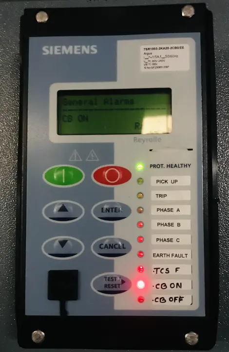
Pic: Siemens Make 7SR1003 Numercial Relay having both overcurrent and earth fault functions
Coordination Between Overcurrent and Earth Fault Protection
While overcurrent and earth fault protection serve different purposes, they must work together as part of a coordinated protection system.
Coordination Hierarchy and Time Grading
In any power system with multiple protective devices, coordination is achieved through time grading. This means that under fault conditions, only the protective device closest to the fault should operate, while upstream devices remain in service as backup protection.
This coordination is achieved by setting progressively longer time delays on upstream protective devices.
For transformer protection, this coordination typically follows this hierarchy:
- Secondary (low-voltage) side instantaneous and inverse-time overcurrent relays trip first for secondary-side faults
- Primary (high-voltage) side inverse-time overcurrent relays provide backup, operating with a time delay only if secondary-side protection fails
- Earth fault protection on the primary side operates independently based on ground current magnitude
The time delay between successive protective elements should be at least 0.3 to 0.5 seconds to ensure reliable discrimination. In modern digital relays, these delays can be measured in tens or hundreds of milliseconds, providing much faster coordination than older electromechanical relays.
Step-by-Step Relay Setting Procedure
- Collect Essential Transformer Data: Obtain the transformer’s rated power (kVA), rated voltages (primary and secondary), impedance (% Z or %X), winding configuration (delta-wye, wye-delta, etc.), and neutral grounding method.
- Calculate Full Load Current: Using the formula presented earlier, calculate the full load current for both primary and secondary sides. This value forms the basis for all pickup settings.
- Select Current Transformer Ratios: Choose CT ratios that will produce convenient secondary currents for relay setting. A 5 A secondary is standard, but 1 A secondaries are also common. The CT ratio should be selected such that the maximum fault current produces a reasonable secondary current, typically in the range of 1-5 A.
- Determine Overcurrent Relay Pickup: Set the primary-side overcurrent pickup between 125% and 150% of full load current for phase protection, or 10% to 60% of full load current for ground protection, depending on system configuration.
- Calculate Time Multiplier Setting: Using coordination curves and the transformer damage curve, determine the appropriate TMS to ensure coordination with downstream devices while staying below transformer damage limits.
- Set Earth Fault Protection: For earth fault or restricted earth fault protection, set the pickup based on system grounding configuration, typically 10% to 60% of winding rated current for solidly grounded systems.
- Verify Coordination: Using time-current coordination curves, verify that all protective devices coordinate properly and that relay operating characteristics stay below transformer damage curves.
Real-World Example: Complete Protection Scheme
Let’s examine a complete protection scheme for a 10 MVA, 33 kV/3.3 kV transformer to illustrate these concepts in practical application.
Transformer Data:
- Rating: 10 MVA
- Primary voltage: 33 kV
- Secondary voltage: 3.3 kV
- Impedance: 8%
- Winding configuration: Delta (HV) – Wye-grounded (LV)
- Neutral grounding: Solid (direct ground connection)
Step 1: Calculate Full Load Currents
Primary current:
\(I_{rated,primary} = \frac{10,000 \times 1000}{\sqrt{3} \times 33,000} = \frac{10,000,000}{57,157} ≈ 175 \text{ A}\)
Secondary current:
\(I_{rated,secondary} = \frac{10,000 \times 1000}{\sqrt{3} \times 3,300} = \frac{10,000,000}{5,715.7} ≈ 1,750 \text{ A}\)
Step 2: Select Current Transformers
Primary side: 200/5 A CT (provides 5 A secondary for 200 A primary)
Secondary side: 2000/5 A CT (provides 5 A secondary for 2000 A primary)
Step 3: Set Primary Side Overcurrent Relay (50/51)
For phase overcurrent protection, use 140% of FLC:
\(I_{pickup} = 175 \times 1.40 = 245 \text{ A primary}\)
Secondary current:
\(I_{sec} = \frac{245 \times 5}{200} = 6.125 \text{ A}\)
For a standard relay with 5 A base current, this corresponds to a multiplier of 1.225.
For time overcurrent protection, set the TMS such that the relay operates in approximately 1 second at 2-3 times pickup current while staying below the transformer mechanical curve.
Step 4: Set Secondary Side Overcurrent Relay
Set secondary phase relay at 125% FLC:
\(I_{pickup} = 1,750 \times 1.25 = 2,187.5 \text{ A primary}\)
Secondary current through relay:
\(I_{sec} = \frac{2,187.5 \times 5}{2,000} = 5.47 \text{ A}\)
This corresponds to a multiplier of approximately 1.09.
Set as instantaneous element (50) with no time delay for fast fault clearing on secondary.
Step 5: Set Earth Fault Protection
Primary side earth fault (51N): Set at 20% of winding rated current:
\(I_{EF} = 175 \times 0.20 = 35 \text{ A}\)
Secondary current:
\(I_{EF,sec} = \frac{35 \times 5}{200} = 0.875 \text{ A}\)
Secondary side earth fault (50N/51N): Set at 10% of full load current:
\(I_{EF} = 1,750 \times 0.10 = 175 \text{ A}\)
Secondary current:
\(I_{EF,sec} = \frac{175 \times 5}{2,000} = 0.4375 \text{ A}\)
Standards and Regulatory Requirements
Transformer protection design must comply with applicable electrical standards and regulations. The primary standards governing transformer protection are:
- IEEE C57.109: IEEE Guide for Liquid-Immersed Transformers Through-Fault-Current Duration. This standard provides transformer damage curves and withstand limits for four categories of transformers based on size. Engineers use these curves to verify that protection settings will not allow transformer damage before protective relays operate.
- IEEE C37.91: IEEE Guide for Protective Relay Applications to Power Transformers. This standard provides guidance on selecting and applying protective relays to transformers, including discussion of various protection schemes and coordination approaches.
- IEC 60255 Series: International standards for measurement and control devices and their interoperability with electrical equipment. These standards define relay characteristics and testing procedures used globally.
- ANSI Standards: Various ANSI standards address grounding practices, protection coordination, and safety requirements that influence transformer protection design.
Maintenance and Testing of Protection Systems
Protection systems require regular testing and maintenance to ensure continued reliable operation. Protective relays should be tested annually, with critical systems tested more frequently. Testing should verify:
- Relay pickup values operate within ±10% of setting
- Relay timing characteristics match expected curves
- Communication with circuit breakers is functioning properly
- Current transformer ratios and winding are correct
Conclusion
Overcurrent and earth fault protection together form a defense against transformer faults and failures. Overcurrent protection addresses phase-to-phase faults and system overloads through carefully selected pickup settings and time delays that ensure proper coordination. Earth fault protection complements this by detecting the ground-related faults that overcurrent protection may miss, particularly those occurring near transformer neutrals.
“Thank you for providing such a comprehensive technical write-up.
You are welcome. I am glad.