In power system protection, relay settings determine how quickly and accurately a fault is detected and cleared. One of the most fundamental terms that every electrical engineer must know is the Plug Setting Multiplier, commonly abbreviated as PSM. It is a simple yet important concept that forms the basis of overcurrent relay operation and coordination.
A solid grasp of this concept will make your work much easier regardless of your experience level. Without knowing how to calculate and apply PSM, it is difficult to set relay operating times or coordinate multiple relays in a protection scheme.
In this technical guide, we will discuss everything you need to know about PSM. We will cover its definition, formula, and calculation method. We will also look at its role in relay coordination, worked-out examples, and frequently asked questions.
1. What is Plug Setting Multiplier (PSM)?
The Plug Setting Multiplier is a ratio that tells us how many times the actual fault current flowing through a relay is greater than the relay’s plug setting current. In simple words, PSM indicates the severity of the fault current relative to the current at which the relay is set to start operating.
Relays used in power system protection especially overcurrent relays are designed to operate when the current exceeds a predetermined value. This predetermined value is called the Plug Setting (PS) or Pick-Up Current. The PSM gives a normalized measure of the fault current with respect to this pick-up value.
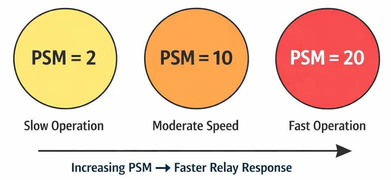
A higher PSM means the fault current is much larger compared to the relay’s pick-up setting. A lower PSM means the fault current is only slightly above the relay’s operating threshold. For example, a PSM of 10 means the fault current is ten times the relay’s pick-up value. A PSM of 2 means the fault current is only double the pick-up value. The relay will respond differently in each case, operating faster for higher PSM values in inverse-time relays.
2. Formula of Plug Setting Multiplier
The PSM is calculated using the following formula:
\(\text{PSM} = \frac{\text{Fault Current in Relay Coil}}{\text{Plug Setting Current of the Relay}}\)
This can also be written as:
\(\text{PSM} = \frac{I_f}{\text{PS}\times \text{CT Secondary Rated Current}}\)
Where:
- \(I_f\) = Fault current flowing through the relay (referred to the CT secondary side)
- \(\text{PS}\) = Plug setting of the relay (expressed as a fraction or percentage)
- CT Secondary Rated Current = The rated secondary current of the current transformer (usually 1A or 5A)
Let us break this formula down step by step to make it clearer.
2.1 Plug Setting (PS)
Before going deeper into PSM, it is important to understand what Plug Setting means.
The Plug Setting of a relay defines the threshold current at which the relay begins to operate. It is expressed as a percentage of the CT secondary rated current. For example, if a relay has a plug setting of 50% and the CT secondary rated current is 5A, then the relay will start to pick up at:
\(\text{Plug Setting Current} =50\% \times 5A = 2.5A\)
Relays come with adjustable plug settings. On electromagnetic relays, you will find a plug bridge or plug setting dial with various taps. These taps are usually marked as 50%, 75%, 100%, 125%, 150%, 175%, and 200%. By inserting the plug into the appropriate tap, you select the desired pick-up current.
In modern numerical relays, the plug setting is entered digitally as a parameter through a keypad or configuration software.
3. How to Calculate PSM — Step by Step with Examples
Let us walk through the PSM calculation using a simple example.
3.1 Example 1: An overcurrent relay is connected to a CT with a ratio of 400/5. The plug setting of the relay is set at 100%. A fault occurs and the fault current on the primary side of the CT is 4000A. Calculate the PSM.
Step 1: Find the fault current referred to the CT secondary side.
Fault current on secondary = Primary fault current / CT ratio = 4000 / (400/5) = 4000 / 80 = 50A
Step 2: Find the plug setting current.
Plug Setting Current = PS × CT secondary rated current = 100% × 5A = 5A
Step 3: Calculate PSM.
PSM = Fault current on secondary / Plug Setting Current = 50 / 5 = 10
This means the fault current is 10 times the relay’s pick-up current. The relay will operate at the time corresponding to PSM = 10 on its time-current characteristic curve.
3.2 Example 2: A relay is connected to a CT of ratio 200/1. The plug setting is 75%. The fault current on the primary side is 3000A. Find the PSM.
Step 1: Fault current on secondary = 3000 / 200 = 15A
Step 2: Plug Setting Current = 75% × 1A = 0.75A
Step 3: PSM = 15 / 0.75 = 20
Here the PSM is 20, which indicates a very heavy fault relative to the relay setting. The relay will operate very quickly for such a high PSM.
4. Role of PSM in Time-Current Characteristics
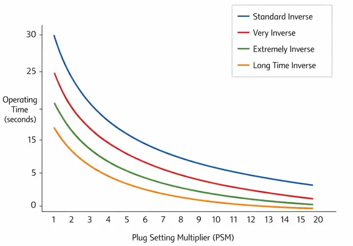
Overcurrent relays especially Inverse Definite Minimum Time (IDMT) relays have time-current characteristic curves. These curves plot the operating time of the relay against the PSM value.
For an IDMT relay, the operating time decreases as the PSM increases. In other words, the higher the fault current (and therefore the higher the PSM), the faster the relay will trip the circuit breaker. At very high PSM values, the relay reaches a minimum operating time known as the definite minimum time, beyond which the operating time does not decrease further regardless of how much the PSM increases.
The operating time of an IDMT relay is given by:
\(\text{Operating Time} = \text{TMS} \times \text{Time from characteristic curve at TMS=1}\)
Here, you first read the operating time from the relay’s characteristic curve at TMS = 1 for the calculated PSM value. Then you multiply that time by the actual TMS setting to get the final operating time. The Time Multiplier Setting (TMS) scales this time up or down depending on the coordination requirements.
So the calculation process is:
- Calculate PSM from the fault current and plug setting.
- Use the PSM value to read the operating time from the relay’s characteristic curve at TMS = 1.
- Multiply this time by the TMS to get the actual operating time.
5. Difference Between PSM and TMS
Students and new engineers sometimes confuse PSM with TMS. Let us clarify the distinction.
| Parameter | PSM (Plug Setting Multiplier) | TMS (Time Multiplier Setting) |
|---|---|---|
| What it defines | How many times the fault current exceeds the pick-up current | A scaling factor that adjusts the operating time of the relay |
| Nature | Calculated value based on fault current | Set by the engineer on the relay |
| Range | Depends on fault level (can be 2, 5, 10, 20, etc.) | Usually between 0.05 and 1.0 |
| Purpose | Determines the point on the time-current curve | Shifts the entire time-current curve up or down |
Both PSM and TMS work together to determine how quickly a relay operates during a fault. PSM locates the point on the curve, and TMS adjusts how fast or slow that curve is. You cannot determine the relay operating time without knowing both values.
6. Why PSM Matters in Relay Coordination
In a radial distribution system with multiple relays in series, it is necessary to coordinate the relays so that the relay nearest to the fault operates first. If that relay fails, the next upstream relay should operate as a backup.
PSM plays a direct role in this coordination. Here is how:
- Each relay in the system will see a different fault current depending on its location and the CT ratio used.
- The PSM for each relay will be different for the same fault.
- By adjusting the plug settings and thereby changing the PSM for each relay, engineers can control which relay operates first and which relay acts as backup.
For instance, consider a system with Relay A closest to the fault and Relay B upstream. When a fault occurs near Relay A, both relays will detect the fault current. However, Relay A will naturally see a higher PSM than Relay B. This is because Relay A is closer to the fault and its CT ratio is selected for the local fault level. The fault current seen by Relay B may be lower due to impedance between the two relay locations or differences in CT ratios.
Additionally, Relay A is given a lower TMS so that it operates faster than Relay B for the same fault. Relay B is given a time delay through a higher TMS. This time difference is called the grading margin. Relay B only trips if Relay A fails to clear the fault within the grading margin time.
7. PSM in Different Types of Overcurrent Relays
7.1 IDMT (Inverse Definite Minimum Time) Relays
In IDMT relays, the operating time varies inversely with the PSM. As PSM increases, operating time decreases. The relationship follows standard curves defined by IEC 60255 or IEEE standards:
- Standard Inverse
- Very Inverse
- Extremely Inverse
- Long Time Inverse
Each curve type has a different mathematical equation relating time and PSM. The choice of curve depends on the application. For example, extremely inverse curves are preferred for protecting systems where fault currents vary widely.
7.2 Definite Time Overcurrent Relays
In definite time relays, the operating time remains constant regardless of how high the PSM goes. The relay operates after a fixed time delay as long as the current exceeds the pick-up value. PSM still matters here because it determines whether the relay will operate at all. If the PSM is less than 1, the fault current is below the pick-up setting and the relay will not respond.
7.3 Instantaneous Overcurrent Relays
These relays operate without any intentional time delay once the current exceeds the set threshold. The concept of PSM is less relevant here because there is no time-current curve involved. However, the pick-up setting still determines whether the relay will respond to a given fault current.
8. Standard IEC Equations Using PSM
The IEC 60255 standard defines the operating time of IDMT relays using the following general formula:
\(t = \frac{(K \times \text{TMS})}{(\text{PSM}^\alpha – 1)}\)
Where:
- \(t\) = Operating time in seconds
- \(K\) and \(\alpha\) = Constants that depend on the curve type
- \(\text{TMS}\) = Time Multiplier Setting
- \(\text{PSM}\) = Plug Setting Multiplier
Note that this equation is valid only for PSM values greater than 1. At PSM = 1, the denominator becomes zero and the equation is undefined. This makes physical sense because at PSM = 1, the current is exactly at the pick-up threshold and the relay is on the verge of operating.
8.1 The constants for standard IEC curves are:
| Curve Type | K | α |
|---|---|---|
| Standard Inverse | 0.14 | 0.02 |
| Very Inverse | 13.5 | 1.0 |
| Extremely Inverse | 80.0 | 2.0 |
| Long Time Inverse | 120.0 | 1.0 |
8.2 Example: For a Standard Inverse relay with TMS = 0.3 and PSM = 5, calculate the operating time.
Solution:
\(t = \frac{(0.14 \times 0.3)}{(5^{0.02} – 1)}\)
First, calculate \(5^{0.02}\):
\(5^{0.02} = e^{(0.02 \times ln(5))} = e^{(0.02 × 1.6094)} = e^{0.03219} = 1.0327\)
\(t = \frac{0.042}{(1.0327 – 1)} = \frac{0.042}{0.0327} = 1.284\, \text{seconds}\)
So the relay will operate in approximately 1.28 seconds for this fault condition.
8.3 Example: For a Very Inverse relay with TMS = 0.3 and PSM = 5, calculate the operating time.
Solution:
\(t = \frac{(13.5 \times 0.3)}{(5^{1.0} – 1)} = \frac{4.05}{5-1}=\frac{4.05}{4}=1.0125\, \text{seconds}\)
Now compare this with the Standard Inverse result of 1.28 seconds. The Very Inverse curve gives a slightly faster operating time at PSM = 5. However, the difference between these two curve types becomes much more noticeable at higher PSM values. This is why the choice of curve type matters in relay coordination studies.
9. Practical Considerations When Working with PSM
9.1 Minimum PSM for Relay Operation
A relay will only operate if the PSM is greater than 1. If the PSM is less than 1, it means the fault current has not reached the pick-up value and the relay will remain inactive. At PSM exactly equal to 1, the current is right at the threshold. The relay may or may not operate reliably at this boundary.
In practice, the relay is designed to operate reliably when PSM is at least 1.5 to 2. At PSM values just barely above 1, the relay may take a very long time to operate. In electromechanical relays, mechanical friction can prevent the disc from rotating at such low multiples. In numerical relays, measurement tolerances can affect the accuracy of detection near the threshold.
9.2 Maximum PSM
Most relay characteristic curves are defined up to a PSM of 20 or 30. Beyond this, the operating time reaches its minimum value and does not change. When calculating operating times for very high fault currents, the PSM should be checked against the relay manufacturer’s data to see the valid range.
9.3 CT Saturation and PSM
At very high fault currents, the current transformer may saturate. When a CT saturates, it no longer accurately reproduces the primary fault current on its secondary side. The actual current flowing through the relay coil may be lower than expected as a result. This means the effective PSM drops and the relay may operate slower than calculated. Engineers must account for CT saturation when selecting CT ratios and relay settings.
Choosing a CT with an adequate knee-point voltage and appropriate burden rating helps avoid saturation during high fault conditions.
10. Step-by-Step Procedure to Set Up a Relay Using PSM
Here is a simplified procedure that protection engineers follow when setting up an overcurrent relay:
Step 1: Determine the maximum load current that the protected circuit will carry under normal conditions.
Step 2: Select the CT ratio so that the CT secondary current under normal load is well within the relay’s range. This is usually a 1A or 5A system.
Step 3: Set the plug setting so that the relay does not operate under normal load conditions. The pick-up current should be set above the maximum load current (with a margin of about 1.2 to 1.5 times the maximum load current).
Step 4: Calculate the PSM for the maximum and minimum fault currents at the protected location.
Step 5: Verify that the PSM for the minimum fault is at least 1.5 to 2. If not, adjust the plug setting or CT ratio.
Step 6: Use the calculated PSM and the desired operating time to select the appropriate TMS from the relay’s time-current curve.
Step 7: Verify coordination with upstream and downstream relays by checking grading margins. The grading margin between successive relays is usually 0.3 to 0.5 seconds.
11. PSM in Numerical Relays vs. Electromechanical Relays
In traditional electromechanical relays, the plug setting is physically adjusted by inserting a plug into different taps on the relay. The relay coil has multiple tapping points. Selecting a higher tap means the relay needs more current to operate. The PSM concept is very visual and straightforward in these relays and you can physically see the plug bridge and the markings.
In modern numerical (digital) relays, the concept of PSM still applies, but the settings are entered through a keypad or software interface. The relay internally calculates the PSM in real time by comparing the measured current against the programmed pick-up setting. Numerical relays often display the PSM value on their screens. This makes it easier for engineers to monitor and troubleshoot during commissioning and testing..
The mathematical relationship remains the same regardless of the relay technology. Whether you are working with an old electromagnetic relay in a substation built decades ago or a brand-new numerical relay in a modern installation, the PSM formula and its interpretation do not change.
12. Conclusion
The Plug Setting Multiplier is a straightforward yet powerful concept in power system protection. It quantifies how severe a fault current is in relation to the relay’s pick-up setting. By calculating PSM, engineers can determine where on the time-current characteristic curve a relay will operate and how fast it will clear a fault.
A proper grasp of PSM, along with TMS, allows protection engineers to coordinate relays accurately and keep power systems safe and reliable.
13. Frequently Asked Questions (FAQs)
PSM is a number that tells you how many times the fault current flowing through a relay exceeds the relay’s pick-up current. For example, if the fault current in the relay coil is 10A and the pick-up current is 2A, then PSM = 5.
PSM = Fault current in relay coil / Plug setting current. The plug setting current equals the plug setting percentage multiplied by the CT secondary rated current.
If PSM is less than 1, it means the fault current has not reached the relay’s pick-up threshold. The relay will not operate and will remain in its normal state.
While the relay begins to operate at PSM just above 1, a PSM of at least 1.5 to 2 is recommended for reliable operation. This accounts for measurement tolerances and mechanical friction in electromechanical relays.
PSM is calculated from the fault current and tells you where on the time-current curve the relay operates. TMS is a setting on the relay that adjusts the operating time by scaling the curve. PSM is a calculated number while TMS is a selected setting.
Yes, PSM can mathematically be any value above 1. However, most relay characteristic curves are only defined up to PSM = 20 or 30. Beyond that, the operating time reaches a definite minimum and stays constant.
For an IDMT relay, as PSM increases, the operating time decreases. The relationship follows inverse curves defined by IEC 60255 or IEEE standards. The exact operating time depends on both the PSM and the TMS setting.
Yes. The concept of PSM applies to all types of overcurrent relays, including numerical relays. The mathematical relationship is the same. Numerical relays calculate PSM internally using their programmed settings and display the value for monitoring..
The minimum PSM for relay operation is 1.0. However, in practice, the minimum recommended PSM is about 1.5 to 2.0 for reliable and timely operation.
First, convert the primary fault current to the CT secondary side by dividing it by the CT ratio. Then divide this secondary fault current by the plug setting current to get the PSM. This two-step process is shown in the worked examples in Section 3 of this article.