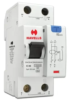
An RCBO, which stands for Residual Current Breaker with Overcurrent is a protective device used in electrical installations. This device combines two protection functions into a single unit. It protects against earth leakage faults (residual current) and also protects against overcurrent conditions like overloads and short circuits. By using an RCBO, you get the combined protection of an MCB (Miniature Circuit Breaker) and an RCD (Residual Current Device) in one compact unit.
The RCBO is widely used in residential, commercial, and industrial electrical systems. It is installed in distribution boards to protect individual circuits. When a fault occurs, the RCBO trips and disconnects the circuit from the power supply. This helps prevent electric shocks, electrocution, and fire hazards caused by electrical faults.
1. Why Do We Need RCBO?
In any electrical installation, there are multiple types of faults that can occur. These include:
- Earth Leakage Faults – When current flows through an unintended path to earth
- Overload Faults – When the circuit draws more current than its rated capacity
- Short Circuit Faults – When live and neutral conductors come into direct contact
Previously, electricians used separate devices to protect against these faults. An MCB was used for overcurrent protection, and an RCD was used for earth leakage protection. However, this approach had a major drawback. When the RCD tripped, it would disconnect all the circuits connected to it. This caused unnecessary power interruption to healthy circuits.
The RCBO solves this problem. Each circuit gets its own individual protection. If one circuit develops a fault, only that circuit trips. All other circuits continue to work normally. This is called selective protection or discrimination.
Example: Consider a house with 6 circuits – 2 lighting circuits, 2 socket circuits, 1 water heater circuit, and 1 air conditioner circuit. If you use a single RCD with multiple MCBs, a fault in the water heater circuit will trip the RCD and cut power to all 6 circuits. But if you use individual RCBOs for each circuit, only the water heater circuit will trip, and the remaining 5 circuits will continue working.
2. Construction and Components of RCBO
An RCBO consists of several internal components that work together to provide dual protection. Let us look at each component in detail.
2.1 Main Components
| Component | Function |
|---|---|
| Current Transformer (CT) | Detects residual current by sensing imbalance between live and neutral conductors |
| Electromagnetic Coil | Provides instantaneous tripping during short circuit conditions |
| Bimetal Strip | Provides delayed tripping during overload conditions |
| Trip Mechanism | Mechanical assembly that opens the contacts when a fault is detected |
| Moving and Fixed Contacts | Carry the load current and open/close the circuit |
| Arc Chute | Extinguishes the arc formed when contacts separate |
| Test Button | Allows manual testing of the residual current function |
| Test Resistor | Creates an artificial imbalance when test button is pressed |
| Electronic Circuit | Processes signals from CT and triggers the trip mechanism |
| DIN Rail Mounting Clip | Allows easy installation on standard DIN rails |
The housing of an RCBO is made from high-quality thermoplastic material that can withstand heat and has good insulating properties. The terminals are made from brass or copper alloy to provide good electrical conductivity.
3. Working Principle of RCBO
The RCBO operates based on two different principles for its two protection functions. Let us examine each one separately.
3.1 Residual Current Protection (Earth Leakage Protection)
The residual current protection function works on Kirchhoff’s Current Law. According to this law, the current entering a circuit must equal the current leaving the circuit. In a healthy circuit, the current flowing through the live conductor equals the current returning through the neutral conductor.
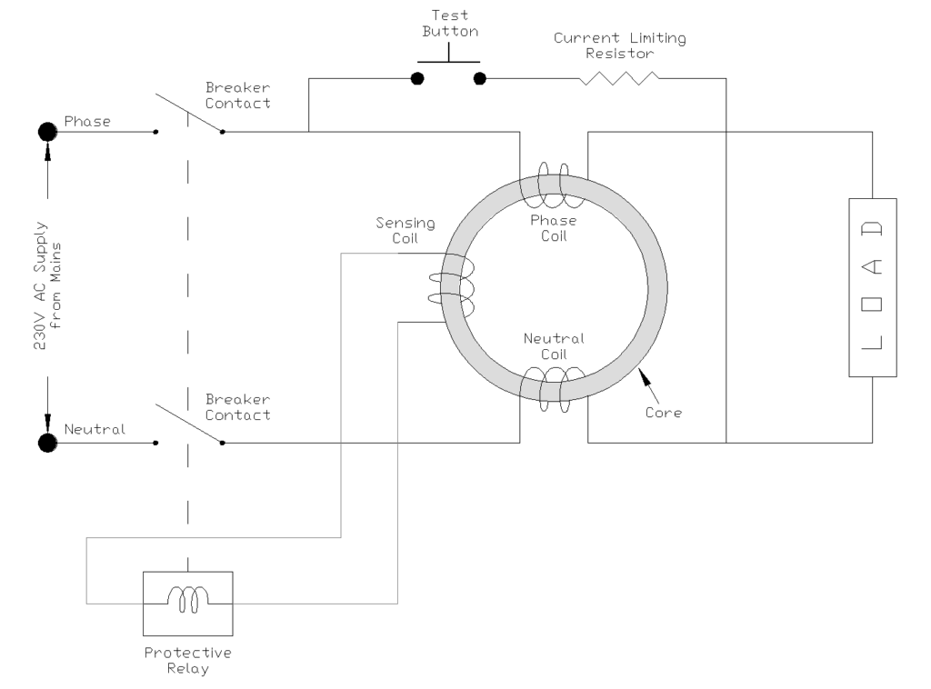
A current transformer (also called a toroidal core or summation current transformer) is placed around both the live and neutral conductors. Under normal conditions, the magnetic fields created by the live and neutral currents are equal and opposite. They cancel each other out, and the net flux in the CT core is zero.
When an earth leakage fault occurs, some current flows through the fault path to earth instead of returning through the neutral. This creates an imbalance between the live and neutral currents. The CT now detects this difference which is called the residual current. The CT generates a small voltage signal proportional to this imbalance.
This signal is fed to an electronic circuit that compares it with a set threshold (rated residual current, typically 30mA for personal protection). If the residual current exceeds this threshold, the electronic circuit activates the trip mechanism, and the RCBO opens the circuit.
Example: Suppose a person accidentally touches a live wire while standing on a wet floor. Current flows from the live wire, through the person’s body, and to earth. This current does not return through the neutral conductor. The RCBO detects this imbalance and trips within milliseconds, saving the person from electrocution.
3.2 Overcurrent Protection
The overcurrent protection function has two parts:
3.2.1 Overload Protection (Thermal Protection)
A bimetal strip is connected in series with the load circuit. When current flows through the strip, it heats up. The strip is made of two metals with different thermal expansion coefficients bonded together. As the temperature increases, the strip bends due to unequal expansion of the two metals.
Under normal load conditions, the heating is minimal and the strip remains straight. When an overload occurs, the excessive current causes significant heating. The strip bends enough to release the trip mechanism. The higher the overload, the faster the strip bends and the quicker the RCBO trips. This provides an inverse time characteristic with higher overloads cause faster tripping.
Example: A 16A RCBO is protecting a socket circuit. If someone connects appliances totaling 20A, the bimetal strip will heat up and cause the RCBO to trip after a few minutes. If the load is 32A (double the rating), the RCBO will trip much faster.
3.2.2 Short Circuit Protection (Magnetic Protection)
An electromagnetic coil (solenoid) is connected in series with the load circuit. Under normal conditions, the magnetic force generated by this coil is not strong enough to move the trip mechanism. However, during a short circuit the current increases to thousands of amperes.
This high current creates a strong magnetic field in the coil. The magnetic force is now sufficient to instantly pull a plunger or armature, which releases the trip mechanism. The RCBO trips within a few milliseconds, and disconnects the circuit before the high short-circuit current can cause damage or fire.
Example: If a live wire accidentally touches a neutral wire due to damaged insulation, a short circuit occurs. The current can jump to 3000A or more. The electromagnetic coil immediately responds to this high current and trips the RCBO in less than 10 milliseconds.
4. Circuit Diagram of an RCBO
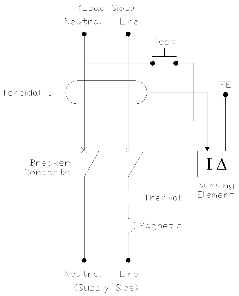
The above diagram illustrates the internal schematic of a single-phase RCBO.
The circuit connects the Supply Side (bottom) to the Load Side (top) with two types of protection. Overcurrent protection is located on the bottom Line wire. It consists of a Magnetic element (semicircle symbol) which detects short circuits and trips instantly and a Thermal element (rectangular symbol) which detects prolonged overloads via heat buildup. Both elements mechanically link to the Breaker Contacts to physically disconnect the power during a fault.
Residual current detection is responsible for identifying earth leakage faults. Both the Line and Neutral conductors pass through a Toroidal Current Transformer (CT). When a fault causes an imbalance between the currents in these wires a current is induced in the transformer’s secondary winding. This signal activates the Sensing Element and the sensing element triggers the breaker contacts to open immediately and cut off the power supply.
Also, a Test button is wired across the conductors. When pressed, it bypasses the balance check to simulate a fault. The FE terminal represents a Functional Earth connection required for the electronics within the sensing element.
5. Types of RCBO
RCBOs are classified into different types based on various parameters. The following tables provide detailed classification.
5.1 Classification by Residual Current Type
| Type | Symbol | Description | Applications |
|---|---|---|---|
| Type AC | ~ | Responds only to sinusoidal AC residual currents | General domestic circuits, resistive loads |
| Type A | ~⎓ | Responds to sinusoidal AC and pulsating DC residual currents | Circuits with electronic equipment, washing machines, EV chargers |
| Type F | Responds to AC, pulsating DC, and mixed frequency residual currents | Variable frequency drives, inverter-fed equipment | |
| Type B | ≋ | Responds to AC, pulsating DC, and smooth DC residual currents | Three-phase systems, PV installations, medical equipment |
| Type B+ | Enhanced Type B with frequency response up to 20kHz | Specialized industrial applications |
5.2 Classification by Trip Characteristic (Overcurrent)
| Curve Type | Instantaneous Trip Range | Typical Applications |
|---|---|---|
| Type B | 3 to 5 times rated current | Resistive loads, domestic installations |
| Type C | 5 to 10 times rated current | Motors, fluorescent lighting, general commercial |
| Type D | 10 to 20 times rated current | High inrush current loads, transformers, welding machines |
| Type K | 10 to 14 times rated current | Motor loads with moderate starting currents |
| Type Z | 2 to 3 times rated current | Semiconductor protection, sensitive electronics |
5.3 Classification by Number of Poles
| Type | Description | Application |
|---|---|---|
| 1P+N (Single Pole + Neutral) | Breaks only the live conductor, neutral passes through CT | Most domestic and commercial single-phase circuits |
| 2P (Double Pole) | Breaks both live and neutral conductors | Where neutral isolation is required |
| 3P+N | Three poles with neutral | Three-phase loads with neutral |
| 4P | Four poles | Three-phase systems requiring neutral isolation |
5.4 Classification by Rated Residual Current
| Rated Residual Current (IΔn) | Protection Level | Application |
|---|---|---|
| 10mA | High sensitivity | Medical locations, special applications |
| 30mA | Personal protection | Socket outlets, wet areas, outdoor circuits |
| 100mA | Fire protection | Circuits where personal protection is provided downstream |
| 300mA | Fire protection | Large installations, industrial applications |
| 500mA | Fire protection | Main incoming protection |
6. Technical Specifications of RCBO
When selecting an RCBO for a particular application, you need to consider various technical specifications. The following table lists the common specifications and their typical values.
| Specification | Symbol | Typical Values | Description |
|---|---|---|---|
| Rated Current | In | 6A, 10A, 16A, 20A, 25A, 32A, 40A, 50A, 63A | Maximum continuous current the RCBO can carry |
| Rated Voltage | Un | 230V, 240V, 415V | Operating voltage of the RCBO |
| Rated Residual Current | IΔn | 10mA, 30mA, 100mA, 300mA, 500mA | The residual current at which the RCBO will trip |
| Breaking Capacity | Icn | 6kA, 10kA, 15kA | Maximum short-circuit current the RCBO can safely interrupt |
| Rated Conditional Short-Circuit Current | Icc | 6kA, 10kA | Short-circuit withstand capacity when protected by backup device |
| Rated Residual Non-Operating Current | IΔno | 0.5 × IΔn | Residual current at which RCBO will not trip |
| Breaking Time | – | <40ms at IΔn, <200ms at 0.5×IΔn | Time taken to trip when residual current is detected |
| Number of Poles | – | 1P+N, 2P, 3P+N, 4P | Number of poles in the RCBO |
| Width | – | 18mm, 36mm per pole | Physical width for mounting |
| Frequency | f | 50Hz, 60Hz | Rated operating frequency |
| Operating Temperature | – | -25°C to +40°C | Ambient temperature range |
7. Difference Between RCBO, RCD, and MCB
Many students and professionals get confused between these three devices. The following table clearly shows the differences.
| Feature | MCB | RCD | RCBO |
|---|---|---|---|
| Full Form | Miniature Circuit Breaker | Residual Current Device | Residual Current Breaker with Overcurrent |
| Earth Leakage Protection | No | Yes | Yes |
| Overload Protection | Yes | No | Yes |
| Short Circuit Protection | Yes | No | Yes |
| Working Principle | Thermal + Magnetic | Electromagnetic (CT based) | Thermal + Magnetic + CT based |
| Test Button | No | Yes | Yes |
| Protection Against Electric Shock | No | Yes | Yes |
| Fire Protection Due to Earth Faults | No | Yes | Yes |
| Number of Circuits Protected | One circuit | Multiple circuits | One circuit |
| Cost | Low | Medium | Higher than MCB+RCD combination per circuit |
| Selectivity | Good | Poor | Excellent |
8. Advantages of RCBO
Using RCBOs in electrical installations offers several benefits:
- Individual Circuit Protection – Each circuit has its own earth leakage and overcurrent protection. A fault in one circuit does not affect other circuits.
- Easy Fault Identification – When an RCBO trips, you immediately know which circuit has the problem. With a common RCD, you have to check all circuits to find the faulty one.
- Space Saving – An RCBO combines MCB and RCD functions in one unit. This saves space in the distribution board compared to using separate devices.
- Better Continuity of Supply – Only the faulty circuit is disconnected. All healthy circuits continue to receive power. This is especially important in commercial and industrial installations.
- Personal and Property Protection – Protects people from electric shock (30mA sensitivity) and property from fire (overcurrent protection).
- Simple Wiring – One device to wire instead of two separate devices.
- Reduced Nuisance Tripping – Individual RCBOs allow for better selection based on the type of load and reduces unwanted tripping.
- Compliance with Regulations – Many electrical codes now require individual RCD protection for certain circuits which RCBOs can provide efficiently.
9. Disadvantages of RCBO
Despite their many benefits, RCBOs have some limitations:
- Higher Initial Cost – RCBOs are more expensive than individual MCBs. For a distribution board with many circuits, the total cost can be significantly higher.
- Limited Availability in Some Ratings – Very high current ratings (above 63A) may not be readily available in RCBO format.
- Complex Internal Construction – More components mean more points of possible failure.
- May Not Be Cost-Effective for All Applications – For simple installations with few circuits, a single RCD with multiple MCBs may be more economical.
- Different Brands May Not Match – RCBOs from different manufacturers may have slightly different dimensions.
- Testing Required – The residual current function should be tested regularly using the test button.
10. Applications of RCBO
RCBOs are used in various electrical installations. Here are the main application areas:
10.1 Residential Applications
- Socket outlet circuits
- Kitchen appliance circuits
- Bathroom and wet area circuits
- Outdoor lighting and power circuits
- Air conditioning circuits
- Water heater circuits
- Garage and workshop circuits
10.2 Commercial Applications
- Office lighting and power circuits
- Server room protection
- Retail shop circuits
- Restaurant and kitchen circuits
- Hotel room distribution boards
- Hospital patient areas
10.3 Industrial Applications
- Machine tool protection
- Motor control circuits
- Conveyor system protection
- Control panel protection
- Variable frequency drive circuits
- Welding machine circuits
10.4 Special Applications
- Swimming pool and fountain circuits
- Construction site temporary installations
- Agricultural installations
- Marina and boat dock power outlets
- Caravan and camping site power points
- Electric vehicle charging stations
11. RCBO Selection Guide
Selecting the right RCBO for your application requires consideration of several factors. Follow this step-by-step guide:
Step 1: Determine the Load Current
Calculate the maximum load current of the circuit. Add up the ratings of all appliances that will be connected to the circuit. Select an RCBO with a rated current (In) equal to or slightly higher than the calculated load current, but not exceeding the cable current-carrying capacity.
Example: A socket circuit will supply a computer (0.5A), a monitor (0.3A), a printer (0.2A), and a heater (10A). Total load = 11A. You should select a 16A RCBO.
Step 2: Select the Trip Characteristic
Choose the trip curve based on the type of load:
| Load Type | Recommended Curve |
|---|---|
| Resistive loads (heaters, lights) | Type B |
| Small motors, fluorescent lights | Type C |
| Large motors, transformers | Type D |
Step 3: Select the Residual Current Rating
| Application | Recommended IΔn |
|---|---|
| Personal protection (sockets, wet areas) | 30mA |
| Additional fire protection | 100mA or 300mA |
| High-sensitivity applications (medical) | 10mA |
Step 4: Select the Residual Current Type
| Load Type | Recommended Type |
|---|---|
| Simple resistive and inductive loads | Type AC |
| Electronic equipment with rectifiers | Type A |
| Variable speed drives | Type F or Type B |
| PV installations | Type B |
Step 5: Check the Breaking Capacity
The RCBO breaking capacity must be equal to or higher than the prospective short-circuit current at the installation point. Common values are 6kA for domestic installations and 10kA for commercial/industrial.
Step 6: Check Other Factors
- Number of poles (1P+N, 2P, etc.)
- Mounting type (DIN rail mounting)
- Dimensions (to fit in distribution board)
- Brand compatibility with existing installation
- Certifications and standards compliance
12. RCBO Installation Guidelines
Proper installation of RCBOs is necessary for safe operation. Follow these guidelines:
12.1 Before Installation
- Turn off the main power supply
- Verify that the RCBO ratings match the circuit requirements
- Check for any physical damage to the RCBO
- Read the manufacturer’s installation instructions
12.2 Mounting
- RCBOs are designed for DIN rail mounting
- Snap the RCBO onto the DIN rail until it clicks into place
- Verify that the RCBO is securely mounted
12.3 Wiring
- Connect the incoming live and neutral to the LINE terminals (usually top)
- Connect the outgoing live and neutral to the LOAD terminals (usually bottom)
- Use properly rated cables with correct termination
- Tighten all terminal screws to the recommended torque (typically 2-3 Nm)
- Do not overtighten as this can damage the terminals
12.4 After Installation
- Restore power supply
- Test the RCBO by pressing the test button
- The RCBO should trip immediately when test button is pressed
- Reset the RCBO and verify that the circuit is working correctly
- Label the RCBO with the circuit it protects
12.5 Important Notes
- Never bypass or jumper out an RCBO
- Do not connect loads directly to the LINE side terminals
- Make sure the neutral of each RCBO is connected to its corresponding circuit only
- Do not mix neutrals between different RCBO circuits (this causes nuisance tripping)
13. Testing and Maintenance of RCBO
Regular testing and maintenance of RCBOs is necessary to confirm their proper operation.
13.1 Test Button Testing
Every RCBO has a test button marked with “T” or “Test.” This button should be pressed regularly to verify that the residual current function is working.
How to Test:
- Press the test button firmly
- The RCBO should trip immediately (within 40ms for Type AC)
- If the RCBO does not trip, it is faulty and must be replaced
- Reset the RCBO by moving the operating lever to OFF and then to ON
Testing Frequency:
| Installation Type | Recommended Testing Frequency |
|---|---|
| Domestic installations | Every 3 months (quarterly) |
| Commercial installations | Monthly |
| Industrial installations | Monthly |
| High-risk areas | Weekly |
13.2 Professional Testing
Besides the test button, RCBOs should also be tested using professional test equipment at regular intervals. This testing verifies:
- Trip Current – The actual residual current at which the RCBO trips
- Trip Time – The time taken to trip at different multiples of rated residual current
- Insulation Resistance – The insulation condition of the RCBO
- Contact Resistance – The condition of the internal contacts
Professional testing is typically done:
- At the time of initial installation
- After any modifications to the circuit
- Every 1 to 5 years depending on the installation type
- After any fault or trip incident
13.3 Maintenance Tips
- Keep the distribution board clean and free from dust
- Check for any signs of overheating (discoloration, burning smell)
- Verify that all terminal connections are tight
- Replace any RCBO that fails the test button test
- Replace RCBOs that show signs of physical damage
- Replace RCBOs according to manufacturer’s recommended service life (typically 10-15 years)
14. Standards and Regulations
RCBOs are manufactured and tested according to international and national standards. The main standards are:
| Standard | Title | Region |
|---|---|---|
| IEC 61009-1 | Residual current operated circuit-breakers with integral overcurrent protection for household and similar uses (RCBOs) – Part 1: General rules | International |
| IEC 61009-2-1 | RCBOs – Part 2-1: Applicability of the general rules to RCBOs functionally independent of line voltage | International |
| EN 61009-1 | European adoption of IEC 61009-1 | Europe |
| BS EN 61009-1 | British adoption of EN 61009-1 | United Kingdom |
| AS/NZS 61009.1 | Australian/New Zealand adoption | Australia/New Zealand |
| IS 12640-2 | Residual current operated circuit-breakers with integral overcurrent protection for household and similar uses | India |
| UL 489 | Molded-Case Circuit Breakers, Molded-Case Switches and Circuit-Breaker Enclosures (includes RCBO requirements) | USA |
14.1 Installation Standards
- IEC 60364 – Electrical installations of buildings
- BS 7671 – Requirements for Electrical Installations (UK Wiring Regulations)
- NEC (National Electrical Code) – USA
- AS/NZS 3000 – Wiring Rules (Australia/New Zealand)
- IS 732 – Code of practice for electrical wiring installations (India)
15. Conclusion
The RCBO (Residual Current Breaker with Overcurrent) is a valuable protective device that combines earth leakage protection and overcurrent protection in a single unit. It provides individual circuit protection, easy fault identification, and better selectivity compared to using a common RCD with multiple MCBs.
16. Frequently Asked Questions (FAQs) About RCBO
A: No. The RCBO requires a proper earth connection to function correctly. Without earth, fault current cannot flow to ground, and the RCBO cannot detect the fault.
A: The appliance likely has an earth leakage fault or a very high inrush current. Get the appliance tested. If it is healthy, you may need a different type of RCBO (Type A instead of Type AC, or Type C instead of Type B).
A: Yes, you can replace an MCB with an RCBO of the same current rating and trip characteristic. This will add earth leakage protection to the circuit. However, you must ensure proper neutral wiring.
A: RCBOs typically have a service life of 10 to 20 years depending on the manufacturer and operating conditions. However, they should be replaced if they fail the test button test or show signs of damage.
A: Random tripping can be caused by cumulative small leakage currents from multiple appliances, moisture in the circuit, loose connections, or a faulty RCBO itself.
A: Type AC responds only to pure sinusoidal AC residual currents. Type A responds to both AC and pulsating DC residual currents. Type A is recommended for circuits with electronic equipment like computers, washing machines, and LED dimmers.