Restricted Earth Fault (REF) protection is a specialized differential protection scheme designed to detect and isolate earth (ground) faults occurring near the neutral point of power transformers. Unlike conventional phase differential protection which has limited sensitivity in the neutral zone, REF protection monitors the neutral current independently and compares it with phase currents to provide sensitive detection of ground faults while maintaining security against external faults.
This protection scheme is essential for modern power systems because it can detect earth faults affecting as little as 5-10% of the transformer winding from the neutral point, providing coverage where other protection schemes are ineffective.
Fundamental Principle of REF Protection
Basic Operating Concept
Restricted Earth Fault protection operates on a simple yet effective principle: a direct earth fault inside a transformer’s star-connected winding will produce a neutral current that is independent of any external conditions.
In a healthy transformer operating under normal or external fault conditions, the algebraic sum of three-phase currents equals the neutral current, which remains zero (or very small) in a balanced system.
However, when an internal earth fault occurs, a path is created directly from the winding to the transformer tank through the earth, causing neutral current to flow even if no comparable current flows on the phase sides.
The core principle can be expressed as: when an internal earth fault develops in the winding closest to the neutral point, it generates a significant neutral current measured by a dedicated neutral current transformer (NCT), while the phase currents remain relatively unaffected. This difference is exploited by the REF relay to distinguish internal faults from external faults and normal operating conditions. The relay continuously monitors the neutral current and compares it with the algebraic sum of the three phase currents at the transformer secondary side.
Physical Configuration and Component Arrangement
A complete REF protection system consists of four key components.
First, the transformer’s neutral point must be earthed through either a resistor (for limited earth-fault current) or directly (for low-impedance grounding).
Second, a sensitive current transformer (NCT) is installed at the transformer neutral point to measure the neutral current flowing to earth during faults. This CT must have high accuracy and minimal ratio error over the full current range.
Third, phase current transformers (CTp) are installed on each of the three phase conductors entering the transformer to measure phase currents. These CTs must be precisely matched with the neutral CT in terms of turn ratio, burden, and saturation characteristics to ensure accurate differential current calculation.
Fourth, the REF protection relay receives secondary currents from all four CTs and performs real-time calculations to detect earth faults. Modern digital relays use sophisticated algorithms that can discriminate between genuine internal faults and false conditions like magnetizing inrush currents and current transformer saturation.
Practical Example
Consider a 100 MVA, 132/11 kV power transformer with a star-connected primary winding.
During normal operation with 100 A per phase current flowing through the phase CTs, the algebraic sum of phase currents \((I_a + I_b + I_c)\) equals approximately zero, and the neutral current is also near zero, indicating balanced operation.
Now imagine a single-phase-to-earth fault occurs at 5% of the winding from the neutral point. This fault creates a direct path through which 500-1000 A of earth current flows from the winding to the transformer tank via the neutral earthing resistor.
The neutral CT detects this 500-1000 A neutral current while the phase currents remain relatively unchanged. The REF relay immediately recognizes this anomaly and initiates a trip to disconnect the transformer from the power system.
Why REF Protection is Essential for Neutral Zone Coverage
Phase differential protection (87T), which is the primary protection for transformer internal faults, becomes less sensitive in the neutral zone because the fault current divides between multiple paths. When a fault occurs very close to the neutral point (within the first 5-15% of the winding), the fault current may be small compared to the phase currents, and the differential element may not detect it reliably.
REF protection eliminates this vulnerability by directly measuring the zero-sequence current (neutral current) which exists only when an earth fault occurs. In the neutral zone, zero-sequence current is the only reliable indicator of fault presence. Traditional overcurrent protection cannot protect this zone adequately because the earth-fault current is often limited by the neutral earthing resistor and does not exceed the pickup setting of general-purpose overcurrent relays. REF protection provides sensitive, rapid detection with operating times typically less than 100-150 milliseconds, ensuring the fault is cleared before significant damage occurs to the transformer insulation.
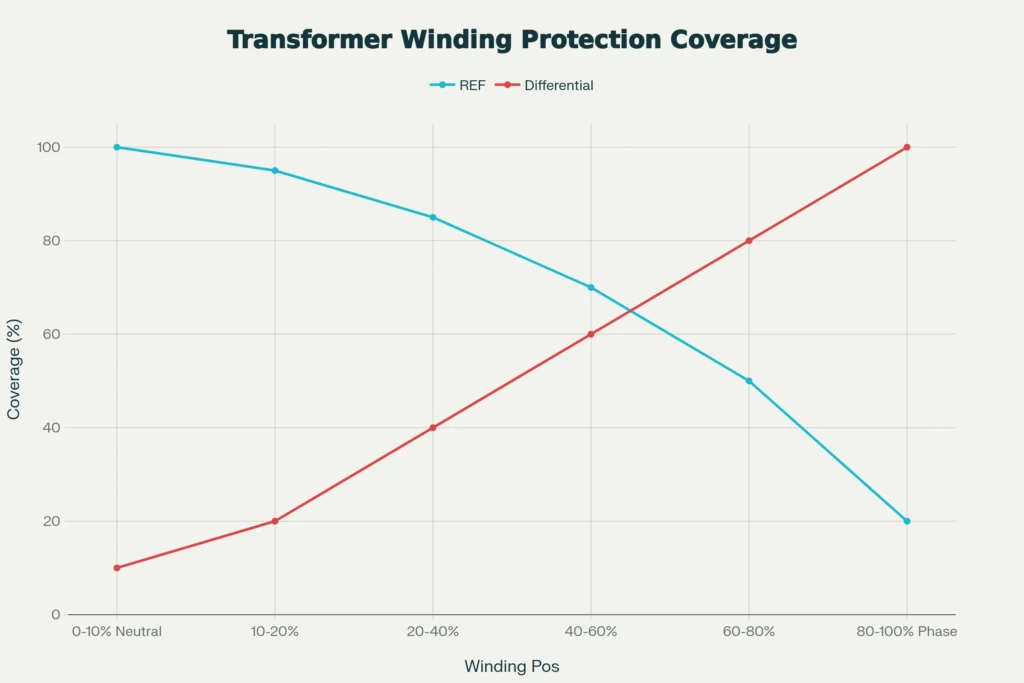
Phase differential protection (87T) provides excellent coverage for faults in the outer portions of the winding (typically 70-90% coverage), it leaves the neutral zone poorly protected (approximately 10-20% coverage). REF protection fills this critical protection gap by providing 85-100% coverage specifically in the neutral zone. Together, REF and 87T protections provide complete winding coverage throughout the entire transformer winding.
Types of REF Protection Schemes: Low-Impedance vs. High-Impedance
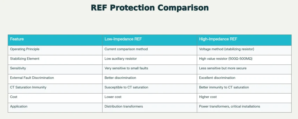
Low-Impedance Restricted Earth Fault Protection
Low-impedance REF (also called current-comparison REF) operates on the principle that the neutral current should equal the algebraic sum of the three phase currents under all normal and external fault conditions. The relay calculates a restraint current (typically the maximum of the three phase currents) and compares the neutral current against this restraint using a percentage differential characteristic, similar to phase differential protection.
In the low-impedance scheme, a small stabilizing resistor (typically 0.5-5 Ω) is used only to provide a defined impedance reference and for CT secondary circuit completion.
The relay characteristic typically follows the equation:
\(I_{op}= k_1\times I_N\)
where \(I_{op}\) is the operating current (neutral current magnitude) and \(k_1\) is the pickup setting constant. The restraint characteristic prevents operation during external faults with CT saturation by using a bias method:
\(\text{Trip if:}\frac{I_N}{I{restraining}}> \text{Setting Percentage}\)
Advantages of Low-Impedance REF
This scheme is highly sensitive to small internal faults near the neutral point, responds rapidly with minimal operating time, and is cost-effective compared to high-impedance schemes. It works well in systems with low-impedance neutral grounding where earth-fault currents are relatively large.
Disadvantages of Low-Impedance REF
The scheme is susceptible to maloperation during external faults when current transformer saturation occurs. When a large external fault creates high currents through the phase CTs, these CTs may saturate, producing distorted secondary currents with erroneous zero-sequence components.
This false zero-sequence current can trigger unwanted REF relay operation, causing a false trip of the transformer. The scheme also requires careful setting and testing to ensure proper coordination with other protections.
High-Impedance Restricted Earth Fault Protection
High-impedance REF operates on a voltage principle rather than current comparison. A very high resistance (typically 500 Ω to 500 MΩ depending on application) is connected in series with the neutral CT secondary circuit. During an internal earth fault, the neutral current flows through this high resistance, developing a voltage across it proportional to the fault current. The relay measures this voltage and operates when it exceeds a preset threshold.
The voltage across the stabilizing resistor is:
\(V_S=(I_N-\frac{I_a+I_b+I_c}{3})\times R_s\)
where \(R_s\) is the stabilizing resistance and \((I_a + I_b + I_c)\) represents any small residual current from phase CT errors.
Advantages of High-Impedance REF
This scheme provides superior immunity to current transformer saturation because the voltage across the high resistor is proportional to the differential current between neutral and phase circuits, and external faults produce minimal voltage across the resistor.
The scheme discriminates excellently against external faults even with severe CT saturation conditions. It is ideal for power transformers and critical installations where security against false trips is important.
Disadvantages of High-Impedance REF
The scheme is less sensitive and cannot detect very small internal faults occurring right at the neutral point. The high impedance and precise component matching requirements make it more expensive to implement. It requires careful calculation of the stabilizing resistor value based on the maximum through-fault current that the relay may experience during external faults.
REF Operating Principle and Relay Logic
The REF protection system continuously acquires electrical signals from the power transformer. The neutral current transformer provides the primary measurement signal—the magnitude and phase of current flowing through the transformer’s neutral point to ground. Simultaneously, the three phase current transformers measure the phase currents on all three windings. Modern digital relays sample these currents at high frequency (typically 4000-8000 samples per second) to capture the dynamic behavior of currents during transient conditions.
Once acquired, these samples are processed using algorithms that calculate RMS values over one cycle of the power frequency. For low-impedance schemes, the restraint current is typically calculated as:
\(I_{Restraint}=max(|I_A|,|I_B|,|I_C|)\)
The operate current (neutral current magnitude) is calculated from the neutral CT secondary current. These two quantities are then compared using a percentage differential function.
Protective Zone Definition and Fault Location Sensitivity
The protective zone of REF protection extends from the transformer neutral point to approximately 85-95% of the winding height toward the phase terminals. This clearly defined zone provides several advantages. First, REF protection specifically protects the “restricted” neutral zone, hence the name Restricted Earth Fault. Second, any fault occurring within this zone produces a distinctive neutral current signature that cannot be confused with external faults.
The sensitivity of REF protection to fault location depends on the fault impedance and neutral grounding impedance. For a fault occurring at distance \(x\%\) from the neutral point in a winding with total turns \(N\), the fault current magnitude is approximately:
\(I_f\approx \frac{E\times x}{R_N+R_f}\)
where \(E\) is the phase voltage, \(R_N\) is the neutral grounding resistance, and \(R_f\) is the fault arc resistance. Even for faults at 5% winding position with 10-20 Ω arc resistance, the fault current is typically sufficient for REF relay detection, especially if the neutral grounding resistance is kept to a reasonable value (typically 5-50 Ω for power transformers).
Harmonic Blocking and Inrush Current Discrimination
One of the most important challenges for REF protection is discriminating between genuine internal earth faults and magnetizing inrush current that occurs when an unenergized transformer is suddenly connected to the power system. During inrush, the transformer core experiences rapid flux changes, producing large distorted currents with significant second harmonic content. Early designs of differential protection (including REF) were sensitive to these inrush currents and would cause false trips.
Modern REF relays incorporate harmonic blocking (or harmonic restraint) schemes that analyze the frequency content of the currents. When the ratio of second harmonic content to fundamental frequency (50/60 Hz) exceeds 15-20%, the relay recognizes this as a probable inrush condition and blocks operation. Internal earth faults produce primarily fundamental frequency currents with minimal harmonic content, so genuine faults continue to be detected even with harmonic blocking active.
The harmonic blocking logic operates according to:
\(\text{Block Operation If:} \frac{I_{2nd Harmonic}}{I_{fundamental}}>0.15\)
Practical Example
A 50 MVA transformer is energized from a dead bus. During energization, the transformer inrush current reaches 8000 A with significant second harmonic content (approximately 2000 A at 100 Hz).
The REF relay calculates the harmonic ratio as 2000/8000 = 0.25, which exceeds the 0.15 threshold.
The relay recognizes this as inrush and blocks its operate signal, preventing a false trip.
Simultaneously, if a real earth fault were occurring in a different transformer section, that fault’s current would be primarily at fundamental frequency with minimal second harmonic, and the relay would operate normally.
Technical Design and Setting Calculations
CT Selection and Specification
The accuracy and reliability of REF protection depend critically on proper current transformer selection and matching. All CTs—neutral and phase—must have identical turn ratios and very similar burden characteristics. In modern systems, neutral CTs typically have turns ratios between 50:1 and 2000:1 depending on the expected neutral current magnitudes, while phase CTs must have identical or carefully compensated ratios to the neutral CT.
The primary technical specification is the CT accuracy class. For REF applications, International standards (IEC 61869) recommend:
- For low-impedance schemes: Class P1 accuracy (minimal knee point voltage around 200-400 V)
- For high-impedance schemes: Specially selected CTs with verified performance under CT saturation conditions
The CT knee point voltage (KPV) is critical. It represents the voltage at which the CT core begins to saturate, limiting accurate current transformation. For low-impedance REF relays protecting transformers in high fault-current systems, the CT knee point voltage must be selected carefully. When the maximum through-fault current (from external three-phase faults) flows through the CT, the secondary voltage developed across it must remain below the knee point to prevent saturation.
The calculation for required knee point voltage in low-impedance schemes follows:
For example, if the maximum three-phase fault current is 25 kA through a CT with 400:1 ratio and secondary winding resistance of 0.5 Ω, then:
A CT with KPV of at least 60-100 V would be required in this case.
REF Relay Setting Procedure
Professional relay settings for REF protection follow a systematic approach that balances sensitivity for internal faults with security against external faults. The first step is to establish the protection zone boundary, typically set at 85-95% of the winding height. For percentage differential setting calculations, the minimum pickup current is typically set at 0.1-0.2 A of neutral current on the relay secondary (equivalent to 10-40 A of primary current depending on CT ratio).
The percentage slope (bias characteristic) for low-impedance schemes is typically set between 20-30%, meaning the relay will operate when:
Where \(I_n\) is neutral current and \(I_restraint\) is the maximum phase current. This ensures sensitivity to small faults while maintaining security against external faults with slight CT errors.
For high-impedance schemes, the stabilizing resistance must be calculated based on the maximum through-fault current from external faults. The standard procedure involves:
- Calculate the maximum phase-to-ground fault current:
- Calculate the secondary current this represents:
- Set stabilizing resistance to limit voltage at maximum fault current to 50-60% of relay operating voltage:
Practical Calculation Example
Consider protecting a 100 MVA, 132/11 kV transformer with star-connected 132 kV winding:
Step 1: Determine neutral grounding arrangement. Assume neutral earthed through 25 Ω resistor.
Step 2: Calculate expected earth-fault current for 5% fault from neutral:
Step 3: Select CTs – use 2000:1 ratio CTs for both phase and neutral to handle the 2180 A fault current plus margin.
Step 4: For low-impedance scheme, set primary pickup at 20 A (corresponding to 0.01 A on relay secondary), providing 90% winding coverage.
Step 5: Set percentage slope at 25% to maintain security against external faults.
Physical Example: REF Protection in Action
To make the concepts concrete, consider this realistic scenario involving a 60 MVA, 150/20 kV distribution transformer in an urban substation.
Normal Operation
The transformer supplies 500 A on the 150 kV side and 3750 A on the 20 kV side.
Phase CTs with 1000:1 ratio on the HV side produce 0.5 A secondary, and phase CTs with 5000:1 ratio on the LV side produce 0.75 A secondary.
The neutral CT (1000:1 ratio on HV side) produces essentially 0 A secondary current because the algebraic sum of phase currents is zero.
The REF relay remains in standby.
External Fault Scenario
A phase-to-phase fault occurs on the 20 kV feeder. This creates a phase-to-phase fault current of approximately 8000 A on the 20 kV side.
Current transformers on both phases measure this current and send it to the phase differential relay, which operates and trips the feeder breaker.
The transformer neutral current remains near zero, so the REF relay does not operate—correct behavior because this fault is external to the transformer.
Internal Earth Fault Scenario
Due to winding insulation aging, a single-phase-to-earth fault develops in the transformer’s high-voltage winding at 8% of the winding from the neutral point. The fault path is now: from the winding → through insulation breakdown → to the transformer tank → through neutral earthing resistor (20 Ω) → to ground.
The fault current magnitude is approximately:
(assuming 10 Ω arc resistance at the fault point)
This 2,890 A neutral current flows through the neutral CT, producing 2.89 A on the secondary (using 1000:1 ratio). The three-phase currents remain essentially at their normal 0.5 A level. The REF relay immediately calculates:
\(\frac{I_N}{I_{restraint}} = \frac{2.89}{0.5} = 5.78 > 0.25 \text{ (the 25% setting)}\)
The relay operates within 30-50 milliseconds, opening the transformer main breaker and isolating the fault. The fault is cleared before it can propagate to a phase-to-phase fault or cause significant thermal damage to the transformer tank.
Conclusion
Restricted Earth Fault (REF) protection is a critical differential protection scheme designed to address the inherent sensitivity limitations of conventional phase differential (87T) protection within the neutral zone of star-connected transformer windings. Independently monitoring the neutral current via a dedicated neutral current transformer (NCT) and comparing it against the algebraic sum of phase currents, REF systems provide sensitive, high-speed detection of internal earth faults affecting as little as 5–10% of the winding from the neutral point.