Generator protection is one of the most important topics in power system engineering. A generator is a high-value machine, and any internal fault can cause severe damage that takes months and millions of dollars to repair. Differential protection, commonly identified by ANSI code 87G, is the primary protection scheme used for large generators. It detects internal faults by comparing the current entering and leaving the generator stator winding.
One of the most important settings in an 87G relay is the slope setting. The slope setting directly controls how the relay responds to the difference between input and output currents. Getting this setting wrong can lead to either unwanted trips during normal operation or missed fault detection during actual faults.
In this technical guide, we will discuss everything you need to know about slope settings for generator differential protection, including its working principle, types, applications, relay settings, coordination strategies, testing methods, and relevant industry standards. Practical examples are included throughout to help you apply these concepts in real-world scenarios confidently.
1. What is Generator Differential Protection (ANSI 87G)?
Generator differential protection operates on a very straightforward principle. Current transformers (CTs) are installed at both ends of the generator stator winding, one set at the terminal end and another at the neutral end. The relay continuously compares the current measured at both ends.
During normal operation, the current entering the stator should equal the current leaving the stator. Any difference between these two values is called the differential current or operating current. If this difference exceeds a set threshold, the relay declares an internal fault and issues a trip command.
The ANSI code 87G specifically refers to the generator differential function. Relays like the GE T60, SEL-300G, Siemens 7UM85, and ABB RET615 all include the 87G function with configurable slope settings.
The differential relay continuously monitors:
- Operating Current \((I_{op})\): The difference between the two CT currents. \((I_{op} = |I_1 – I_2|)\)
- Restraint Current \((I_r)\): A measure of the total current flowing through the protected zone. \((I_r = \dfrac{(|I_1| + |I_2|)}{2})\)
The ratio between operating current and restraint current forms the basis of the slope characteristic.
2. Why Do We Need Slope Settings?
In an ideal system, both CTs would produce perfectly matched secondary currents during normal operation. The differential current would be zero, and the relay would remain stable. In practice, however, the system is never perfectly ideal.
Several factors cause a false differential current to appear even when no internal fault exists. These factors include:
- CT Mismatch: Two CTs of similar ratings rarely produce exactly the same secondary current. Manufacturing tolerances, core characteristics, and burden differences all contribute to a small imbalance.
- CT Saturation: During heavy through-fault conditions, one CT may saturate before the other. This creates a large false differential current that can trip the relay unnecessarily.
- Magnetizing Inrush: When a generator is connected to the system, a transient magnetizing current flows that can appear as a differential current.
- CT Errors at High Currents: At high load or fault currents, the CT error increases. This means the false differential current also increases in proportion to the load current.
If the relay used a fixed pickup threshold, it would either trip falsely during high current conditions or miss real faults at low current levels. The slope setting solves this problem by making the relay’s pickup threshold proportional to the restraint current. This is called percentage differential protection.
3. What Is the Slope Characteristic in 87G Protection?
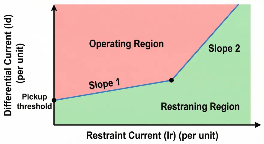
The slope characteristic is a graph that defines the boundary between the operate region and the restrain region of the differential relay. The Y-axis shows the operating current \((I_{op})\), and the X-axis shows the restraint current \((I_r)\).
The relay trips when the operating current exceeds the value defined by the slope characteristic at any given restraint current level. The relay remains stable when the operating current falls below this boundary.
The slope is expressed as a percentage and is calculated using the formula:
\(\text{Slope (%)}=\dfrac{I_{op}}{I_r}\times 100\)
For example, if the slope is set to 20%, the relay will trip only when the differential current exceeds 20% of the restraint current. If the restraint current is 5A, the relay will trip when the differential current exceeds 1A.
Modern digital relays offer a dual-slope or multi-slope characteristic. This gives the relay different sensitivity levels across different operating regions.
The three sections of a typical 87G characteristic are:
- Minimum Pickup Section: A flat horizontal line at the bottom left, defining the minimum differential current required to operate the relay regardless of restraint current.
- Slope 1 Region: A straight line with a gentle upward slope, applied in the normal operating current range.
- Slope 2 Region: A steeper straight line, applied in the high current range where CT saturation is more likely.
4. The Minimum Pickup Setting
Before looking at slope values, the minimum pickup setting deserves attention. This is the lowest differential current level at which the relay can operate, independent of the restraint current.
The minimum pickup (also called \(I_{S1}\) or \(I_{diff(minimum)}\) is set in the range of 0.05 pu to 0.2 pu of the rated current. A common default setting used across many relay manufacturers is 0.1 pu (10% of rated current).
Setting the minimum pickup too low makes the relay susceptible to operating due to CT errors and noise at no-load conditions. Setting it too high reduces sensitivity to turn-to-turn faults or high-resistance internal faults.
For a generator rated at 100 MVA, 11 kV, the rated current is approximately:
\(I_{rated} = \dfrac{100 \text{MVA}}{\sqrt{3} \times 11 \text{kV}} = 5249 A\)
If the CT ratio is 6000/5 A, the secondary rated current is:
\(I_{secondary} = \dfrac{5249}{6000} \times 5 = 4.37 A\)
A minimum pickup of 0.1 pu means the relay will operate if the differential current exceeds 0.437 A in secondary quantities, regardless of the restraint current level.
5. Slope 1 Setting
Slope 1 is the lower slope of the dual-slope characteristic. It covers the normal load operating region where the restraint current is at or near the rated value. The slope 1 setting is chosen based on the expected CT mismatch and steady-state errors.
The slope 1 setting is expressed as:
Slope 1 (%) = (Maximum CT mismatch + CT ratio error + relay error) × Safety Margin
In practice, relay manufacturers and protection engineers commonly set Slope 1 in the range of 15% to 30%. A value of 20% is widely used as a starting point for generators with good CT matching.
5.1 How to Choose the Right Slope 1 Value
The maximum allowable CT error is defined by CT class. For a class 5P10 CT, the maximum composite error is 5% at 10 times rated current. At rated current, the error is much less around 1% to 3%.
Consider the following example:
- CT mismatch error: 3%
- CT burden error: 2%
- Relay measurement error: 2%
- Total error: 7%
- With a safety margin of 2×: Slope 1 = 14%
Rounding up to the nearest available setting and adding a healthy margin, a Slope 1 setting of 20% is appropriate. Some engineers prefer 25% for generators with older or lower-accuracy CTs.
5.2 Slope 1 Transition Point
Slope 1 is applied from the minimum pickup level up to a certain restraint current value. This transition point is usually set at 1.0 pu to 2.5 pu of the rated current. Above this point, the relay switches to Slope 2.
A common setting for the Slope 1 to Slope 2 transition is at \(I_r = 2.0 \text{pu}\) of rated current.
6. Slope 2 Setting
Slope 2 is the steeper portion of the relay characteristic. It is applied in the high current region above 2.0 pu of rated current. In this region, CT saturation becomes a real concern particularly during external through-fault conditions.
When a heavy external fault occurs, a large current flows through the generator and through both CTs. If one CT saturates while the other does not, a large false differential current appears. Without a steep Slope 2, the relay might trip falsely for this external fault.
The Slope 2 setting must be steep enough to prevent operation during CT saturation. It is typically set in the range of 40% to 80%. A common setting is 50% to 60% for most large generators.
6.1 How to Choose the Right Slope 2 Value:
The slope 2 value is chosen based on the worst-case CT saturation error during a through-fault condition. This depends on:
- The maximum external fault current the generator can supply
- The CT accuracy class and burden
- The CT knee-point voltage relative to the secondary burden voltage
For a generator that can supply up to 10 pu fault current through an external fault, and where the CT can saturate to produce up to 40% false differential current, a Slope 2 of 60% provides adequate security.
Slope 2 must never be set above 87% in most relay implementations, because at that level, even genuine internal faults during a fault condition might not produce enough differential current to cross the operate boundary.
The general guideline from IEEE Std C37.102 (Guide for AC Generator Protection) recommends that the slope settings be chosen to maintain relay stability for the maximum through-fault current while maintaining sensitivity for internal faults.

7. Relationship Between Slope 1, Slope 2, and Fault Sensitivity
There is a trade-off between security and sensitivity in slope setting selection.
A lower slope makes the relay more sensitive to internal faults. It will detect even small internal faults. The risk is that the relay may operate unnecessarily for external faults or CT errors.
A higher slope makes the relay more secure against false trips. The relay remains stable for external faults and CT saturation. The risk is that small internal faults might not generate enough differential current to cross the higher slope characteristic.
A well-designed dual-slope characteristic manages both concerns. Slope 1 provides sensitivity in the normal operating range, and Slope 2 provides security at high current levels.
For a turn-to-turn fault involving only a few turns of the stator winding, the differential current produced is very small. In such cases, even a Slope 1 of 20% might be too high to detect the fault reliably. This is one reason why additional protection functions like split-phase protection or volts-per-hertz protection are used alongside 87G.
8. CT Requirements for 87G Slope Settings
The CT selection directly affects the slope settings that are required. If high-quality, well-matched CTs are installed, lower slope settings can be used. Poor CT matching forces the engineer to increase the slope, which reduces sensitivity.
The CTs used for generator differential protection should ideally meet the following requirements:
- CT Accuracy Class: CTs should ideally be class 5P20 or better. This means the composite error is within 5% at 20 times rated current.
- CT Knee-Point Voltage: The knee-point voltage of the CT should be at least two times the maximum secondary burden voltage during the maximum fault current. This prevents premature saturation.
- CT Matching: Both sets of CTs (terminal end and neutral end) should have the same ratio, class, and burden. Mismatches in ratio can be corrected in modern relays through software ratio correction, but physical matching is always preferable.
IEEE Std C57.13 provides the standard requirements for instrument transformers used in protection applications. Following this standard during CT selection avoids many slope setting problems.
9. Practical Slope Setting Example
Let us work through a practical setting example for an 87G relay.
9.1 Generator Data:
- Rating: 150 MVA, 13.8 kV, 50 Hz
- Rated Current: \( \dfrac{150 \text{MVA}}{\sqrt{3} × 13.8 kV} = 6277 A\)
- CT Ratio (Terminal End): 7000/5 A
- CT Ratio (Neutral End): 7000/5 A
- CT Class: 5P20
- Relay: SEL-300G
Step 1: Calculate Secondary Rated Current
\(I_{secondary} = \dfrac{6277}{7000} \times 5 = 4.48 A\)
Step 2: Set Minimum Pickup
Use 10% of rated secondary current \(= 0.10 \times 4.48 = 0.448 A\)
In per-unit terms, set \(I_{diff(minimum)} = 0.10 \text{pu}\)
Step 3: Set Slope 1
CT mismatch error = 2%
CT burden error = 2%
Relay error = 1.5%
Total = 5.5%
Apply safety factor of 2.5× → 5.5 × 2.5 = 13.75%
Round up → Slope 1 = 15%
Apply Slope 1 from 0.10 pu to 2.0 pu of rated current.
Step 4: Set Slope 2
Maximum through-fault current = 8 pu
CT saturation analysis shows maximum false differential current = 35%
Apply safety factor of 1.5× → 35 × 1.5 = 52.5%
Round up → Slope 2 = 55%
Apply Slope 2 above 2.0 pu of rated current.
Step 5: Summary of Settings
| Parameter | Setting Value |
|---|---|
| Minimum Pickup (Idiff min) | 0.10 pu |
| Slope 1 | 15% |
| Slope 1 End Point | 2.0 pu |
| Slope 2 | 55% |
These settings should be verified through secondary injection testing and checked against load flow data before commissioning.
10. How Slope Settings Are Applied in Modern Digital Relays
Modern numerical relays implement the 87G slope characteristic through software algorithms. The relay samples the current waveform at high speed (typically 32 to 64 samples per cycle) and continuously calculates \(I_{op}\) and \(I_r\).
Each relay manufacturer has its own specific implementation, but the overall concept remains the same. Here is how slope settings appear in common relay platforms:
- SEL-300G: Uses parameters O87P (minimum pickup), SLP1 (Slope 1 in percent), and SLP2 (Slope 2 in percent). The breakpoint between Slope 1 and Slope 2 is fixed at 3.0 pu in some versions or adjustable in others.
- GE T60: Uses percentage differential settings with Slope 1 and Slope 2 in percent. The transition restraint current is a separate adjustable setting.
- Siemens 7UM85: Uses IS1 (minimum pickup), K1 (Slope 1 coefficient), IS2 (transition point), and K2 (Slope 2 coefficient). Slopes are entered as decimal values (e.g., 0.20 for 20%).
- ABB RET615: Uses IdMin (minimum pickup) and slope settings in percentage values with a configurable transition point.
Always refer to the relay instruction manual when entering slope settings. The exact variable names and entry formats vary between manufacturers and firmware versions.
11. Effect of Slope Settings on Relay Operating Time
The slope setting also indirectly affects the relay operating time. A relay operating with a large margin above its slope characteristic will produce a faster trip output compared to a relay that barely crosses the operate boundary.
For a genuine internal three-phase fault, the differential current is very large, often exceeding 10 pu or more. The relay operates in less than one cycle for such faults in the range of 8 to 20 milliseconds.
For a high-resistance internal fault where the differential current barely exceeds the slope boundary, the relay may take a few cycles to confirm the operation. Some relays include a time delay setting for the 87G function though setting a delay on differential protection is generally not recommended for large generators.
IEEE Std C37.102 recommends that the 87G function should operate without intentional time delay. The speed of operation is one of the main advantages of differential protection over other protection schemes.
12. Common Mistakes in Slope Settings
Several common mistakes occur in the field when setting up 87G slope settings.
Mistake 1 – Setting Slope Too High for Security
Some engineers set Slope 2 at 80% or higher to ensure the relay never trips for external faults. This approach sacrifices sensitivity for security. An internal fault during an external fault condition may go undetected with such a high slope.
Mistake 2 – Not Accounting for CT Ratio Correction
If the CTs on both sides do not have identical ratios, the relay must apply a ratio correction factor. Forgetting this correction introduces a constant offset in the differential current, which forces a higher slope setting to compensate.
Mistake 3 – Ignoring the Transition Point Setting
Setting the Slope 1 to Slope 2 transition point too low (e.g., at 1.0 pu) means the steeper Slope 2 is applied during normal load conditions. This reduces sensitivity unnecessarily during the load current range.
Mistake 4 – Not Verifying Settings with Secondary Injection
Slope settings must be verified by secondary current injection testing after commissioning. Testing confirms that the relay operates within the expected operate and restrain regions.
13. Industry Standards for 87G Slope Settings
Several industry standards provide guidance on generator differential protection slope settings.
IEEE Std C37.102-2006 — Guide for AC Generator Protection: This is the primary standard for generator protection in North America. It covers the 87G function, CT requirements, and provides guidance on slope setting selection.
IEC 60255-111:2017 — Measuring Relays and Protection Equipment – Functional Requirements for Distance Protection: Provides relay performance standards applicable to differential protection elements.
IEC 60255-12 — Electrical Relays – Part 12: Biased (Percentage) Differential Relays: Specifically covers percentage differential relay requirements, including slope characteristic definitions and accuracy requirements.
NERC PRC-019-2 — Coordination of Generating Unit or Plant Capabilities, Voltage Regulating Controls, and Protection: Requires utilities in North America to coordinate generator protection settings, including 87G, with machine capabilities.
CIGRE Technical Brochure 479 — Protection of Large Generator-Transformer Units: Provides international best practices for large generator protection, including differential protection slope setting guidelines.
Following these standards during setting selection ensures compliance, safety, and system reliability.
14. Testing and Verification of Slope Settings
After slope settings are programmed into the relay, field testing is mandatory before the generator is commissioned. The testing process verifies that the relay operates correctly within the defined operate and restrain regions.
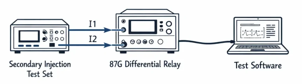
14.1 Secondary Injection Testing
An injection test set (such as the Omicron CMC 356 or Megger SMRT36) is used to inject currents into the relay’s CT inputs. The test engineer applies currents at known Iop and Ir values and verifies whether the relay operates or restrains as expected.
14.2 Test Points to Verify
- Minimum pickup point — verify the relay operates at Idiff minimum.
- A point on the Slope 1 boundary — verify the relay is on the edge of operation.
- A point inside the restrain region on Slope 1 — verify the relay does not trip.
- A point on the Slope 2 boundary — verify the relay operates at the correct level.
- A point inside the restrain region on Slope 2 — verify security during CT saturation simulation.
14.3 Documenting Test Results
All test results must be recorded in the relay commissioning report. The records should include the injected currents, expected relay behavior, and actual relay behavior. These records are required for compliance under NERC PRC-019-2 and similar standards.
15. Conclusion
Slope settings in generator differential protection (87G) play a direct role in the relay’s ability to detect genuine internal faults while remaining stable during external faults, CT saturation, and load transients. Slope 1 provides sensitivity in the normal operating range, and Slope 2 provides security at high current levels. Selecting the right values requires careful analysis of CT accuracy, maximum through-fault current, and generator ratings.
The minimum pickup, Slope 1, Slope 2, and the transition point must all be set together as a coordinated group. Industry standards like IEEE Std C37.102 and IEC 60255-12 provide the framework for making these decisions. Field testing using secondary injection is the final step that confirms the settings work correctly in practice.
16. Frequently Asked Questions (FAQs)
The slope setting controls the ratio of operating current to restraint current at which the relay will operate. A 20% slope setting means the relay trips when the differential current exceeds 20% of the restraint current at any given operating point.
Slope 1 applies during the normal load current range from the minimum pickup level up to about 2.0 pu of rated current. It is set at a lower percentage (15–30%) to maintain sensitivity for internal faults. Slope 2 applies at higher current levels above 2.0 pu where CT saturation is a risk. It is set steeper (40–80%) to prevent false trips during external through-faults.
If Slope 1 is set too low, the relay becomes too sensitive and may trip for small differential currents caused by CT mismatch or measurement errors during normal operation.
If Slope 2 is set too high, the relay loses sensitivity in the high current region. An internal fault that occurs during a heavy load condition might not produce enough differential current to cross the steep Slope 2 boundary.
CT saturation causes one CT to produce a lower secondary current than the actual primary current. The other CT may not saturate at the same time, creating a large false differential current.
Some relay manufacturers allow setting both slopes to the same value, which effectively creates a single-slope characteristic. This is acceptable for smaller generators or applications where the CT quality is very high. For large generators exposed to high through-fault currents, a dual-slope characteristic is strongly recommended because it offers better balance between security and sensitivity.
For large generators with high-quality, well-matched CTs, the Slope 1 setting is commonly in the range of 15% to 25%. A setting of 20% is frequently used as a standard starting point.
Slope settings are verified through secondary current injection testing. An injection test set is used to apply known combinations of Iop and Ir into the relay CT inputs. The test verifies that the relay operates for points above the slope characteristic and restrains for points below it.
Generator differential protection should operate without intentional time delay. The 87G function is a unit protection scheme, meaning it operates only for internal faults within its protection zone. There is no coordination requirement with other downstream protection.