A star delta starter is a widely used method for starting three-phase induction motors. When a motor starts directly from the main supply, it draws a very high starting current which can be 5 to 7 times the normal full load current. This high current can damage the motor windings and also affect other equipment connected to the same power supply. To overcome this problem, engineers developed various starting methods and the star delta starter is one of the most popular and cost-effective solutions.
The star delta starter reduces the starting current by first connecting the motor windings in star configuration and then switching to delta configuration once the motor reaches a certain speed. This simple yet effective technique has been used in industries for many decades and continues to be a preferred choice for medium-sized motors.
In this technical guide, we will discuss the working principle, star connection, delta connection, Components, Power Circuit, Control Circuit, applications, advantages, etc., of Star Delta Starter. We will also, compare the star delta starter with DOL starter.
1. Why Do We Need a Star Delta Starter?
When you switch on a three-phase induction motor directly it behaves like a transformer with a short-circuited secondary winding. At standstill, the rotor is stationary and the slip is maximum (equal to 1). This causes the motor to draw a very large current from the supply. For example, if a motor has a full load current of 100 amperes, its starting current could be as high as 600-700 amperes.
This high starting current creates several problems. First, it causes a voltage drop in the supply system which can affect other machines and equipment. Second, the electrical utility companies charge penalties for high starting currents. Third, the motor windings experience thermal stress due to excessive current flow. Fourth, the mechanical parts of the motor and the connected load experience sudden jerks.
A star delta starter solves these problems by reducing the starting current to approximately one-third of the direct-on-line starting current. This reduction happens because the voltage applied to each winding in star connection is only 1/√3 (about 58%) of the line voltage.
2. Basic Working Principle of Star Delta Starter
The star delta starter works on a simple principle. The same motor can be connected in two different configurations: star (Y) and delta (Δ). In star connection, one end of each winding is connected to a common point called the neutral or star point. In delta connection, the windings are connected end to end, forming a closed triangle.
When motor windings are connected in star, each winding receives a phase voltage, which is line voltage divided by √3. When connected in delta, each winding receives the full line voltage. Since the starting current depends on the applied voltage, reducing the voltage reduces the starting current.
For example, consider a motor designed for 415V delta operation. When connected in star during starting, each winding receives 415/√3 = 240V. This reduced voltage results in reduced starting current. Once the motor accelerates to about 75-80% of its rated speed, the connection is changed from star to delta and the motor runs at full voltage.
The mathematical relationship of starting current with star connection equals:
\( I_{st(star)} = \frac{I_{st(delta)}}{\sqrt{3}} \)
2.1 Voltage and Current Relationships
The theoretical foundation of star delta starting relies on fundamental electrical principles governing three-phase systems. In star connection, the relationship between line and phase voltages follows the equation \(V_L=\sqrt{3}\times V_Ph\), while in delta connection, line and phase voltages are equal \(V_L=V_Ph\).
For star connection:
\( V_{ph(star)} = \frac{V_L}{\sqrt{3}} \)
For delta connection:
\( V_{ph(delta)} = V_L \)
The phase current in star connection is:
\( I_{ph(star)} = \frac{V_{ph(star)}}{Z} = \frac{V_L}{\sqrt{3} \times Z} \)
Where \(Z\) represents the motor impedance per phase.
Starting torque reduction occurs proportionally to the square of the voltage reduction, resulting in:
\( T_{start(star)} = \frac{T_{start(delta)}}{3} \)
This relationship derives from the torque equation \(T=k\times V^2\), where \(k\) is a constant dependent on motor design parameters.
2.2 Power Relationships
The power consumed during star starting is significantly reduced compared to delta starting:
\( P_{start(star)} = \frac{P_{start(delta)}}{3} \)
This power reduction contributes to lower thermal stress on motor windings and reduced electrical system loading during the starting period.
2.3 Current Calculations
The line current reduction can be expressed mathematically. For a motor with impedance \(Z_e\) per phase referred to the stator:
In delta starting:
\( I_{st(\delta)l} = \sqrt{3} \times I_{st(\delta)p} = \sqrt{3} \times \frac{V_L}{Z_e} \)
In star starting:
\( I_{st(\star)l} = I_{st(\star)p} = \frac{V_L}{\sqrt{3} \times Z_e} \)
Therefore, the current reduction ratio is:
\( \frac{I_{st(\star)l}}{I_{st(\delta)l}} = \frac{1}{3} \)
2.4 Torque Development Equations
The developed torque in an induction motor is proportional to the square of the applied voltage:
\( T \propto V^2 \times \frac{R_2/s}{R_2^2 + (sX_2)^2} \)
Where:
- \(R_2\) = rotor resistance referred to stator
- \(X_2\) = rotor reactance referred to stator
- \(s\) = slip
During star starting, with voltage reduced to \(V/\sqrt{3}\), the torque becomes:
\( T_{star} = T_{delta} \times \left(\frac{1}{\sqrt{3}}\right)^2 = \frac{T_{delta}}{3} \)
3. Components of a Star Delta Starter
A star delta starter consists of several components that work together to perform the starting operation. Each component has a specific function in the circuit.
3.1 Main Contactor (K1 or KM)
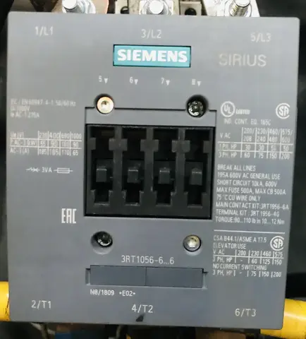
The main contactor is the primary switching device in a star delta starter. It connects the three-phase power supply to the motor terminals U1, V1, and W1. This contactor remains closed during both star and delta operations meaning it stays energized from the moment you press the start button until you press the stop button.
The main contactor must be rated to carry the full load current of the motor continuously. It is typically the largest contactor in the starter panel. When selecting the main contactor consider the motor’s rated current, the AC category (AC3 for motor loads), and the operational voltage.
3.2 Star Contactor (K2 or KY)
The star contactor creates the star connection by short-circuiting the three end terminals of the motor windings (U2, V2, and W2) together. When this contactor closes it forms a common neutral point and the motor operates in star configuration with reduced voltage across each winding.
This contactor operates only during the starting period for 5 to 15 seconds. Once the timer completes its preset duration, the star contactor opens and remains open during normal running. Since it carries only the phase current and operates for a short time, it can be rated at approximately 33% of the main contactor rating.
3.3 Delta Contactor (K3 or KD)
The delta contactor creates the delta connection by interconnecting the motor windings in a triangular pattern. It connects terminal U2 to W1, V2 to U1, and W2 to V1. When this contactor closes, each motor winding receives the full line voltage and the motor operates at its rated capacity.
The delta contactor energizes after the star contactor opens following the timer changeover. It remains closed during the entire running period of the motor. Like the star contactor, it carries phase current and can theoretically be rated at 58% of motor current. However, during the transition from star to delta, a brief current spike occurs, so many designers select delta contactors with higher ratings to handle this transient condition safely and extend the contactor’s service life.
3.4 Timer (On-Delay Timer)
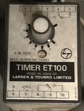
The timer controls the duration of star connection before switching to delta. It is an on-delay timer meaning it starts counting when energized and changes its contact state after the preset time expires. The timer has both normally open and normally closed contacts that change position simultaneously after the delay period.
The normally closed contact is connected in series with the star contactor coil while the normally open contact is connected in series with the delta contactor coil. When the timer times out, the normally closed contact opens (de-energizing the star contactor) and the normally open contact closes (energizing the delta contactor).
Timer settings range from 5 to 30 seconds depending on motor size, load characteristics, and acceleration requirements.
3.5 Overload Relay (OLR)
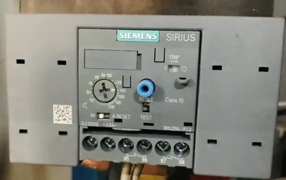
The overload relay protects the motor from damage due to excessive current draw. It monitors the current flowing through the motor and trips the control circuit if the current exceeds the set value for a prolonged period. This prevents motor winding damage from overheating caused by mechanical overload, phase imbalance, or other abnormal conditions.
Modern thermal overload relays use bimetallic strips that bend when heated by excessive current. Electronic overload relays use current transformers and microprocessors for more accurate protection. The relay has a current adjustment dial that should be set according to the motor nameplate full load current. It also features a reset button (manual or automatic) and auxiliary contacts that break the control circuit when tripped.
3.6 Circuit Breaker / MCCB
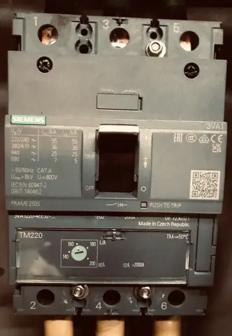
The circuit breaker or Molded Case Circuit Breaker (MCCB) provides short circuit protection for the motor and starter circuit. It disconnects the power supply instantly when a short circuit or severe overcurrent occurs. Unlike fuses, circuit breakers can be reset after tripping which makes them more convenient for repeated use.
MCCBs used in motor circuits are rated for motor protection duty with magnetic trip settings suitable for handling the high starting currents of induction motors. The breaker rating is selected based on the motor full load current and starting current characteristics.
3.7 HRC Fuses
High Rupturing Capacity (HRC) fuses provide backup short circuit protection in star delta starter circuits. They are designed to interrupt very high fault currents safely without causing damage to surrounding equipment. HRC fuses contain a fuse element surrounded by quartz sand, which helps extinguish the arc during fault interruption.
3.8 Start Push Button (NO Contact)
The start push button initiates the motor starting sequence. It is a momentary contact switch with a normally open (NO) configuration. When pressed it completes the control circuit and energizes the main contactor and star contactor coils. Releasing the button opens the contact, but the motor continues running due to the holding circuit.
3.9 Stop Push Button (NC Contact)
The stop push button halts motor operation by breaking the control circuit. It has a normally closed (NC) configuration, meaning it allows current flow in its normal state. When pressed, it opens the circuit and de-energizes all contactors and stopping the motor. The button returns to its closed position when released.
4. Power Circuit of Star Delta Starter
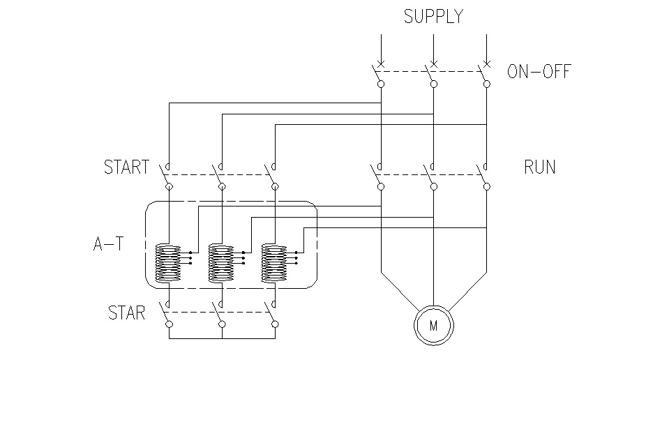
The power circuit of a star delta starter connects the motor windings to the supply through the contactors. The circuit has six terminals from the motor, marked as U1, V1, W1, U2, V2, and W2. U1, V1, and W1 are the start terminals of the three windings, while U2, V2, and W2 are the end terminals.
The main contactor connects the supply lines R, Y, and B to terminals U1, V1, and W1 respectively. The delta contactor connects U1 to W2, V1 to U2, and W1 to V2, creating the delta configuration. The star contactor short-circuits terminals U2, V2, and W2 together, creating the star point.
5. Control Circuit of Star Delta Starter
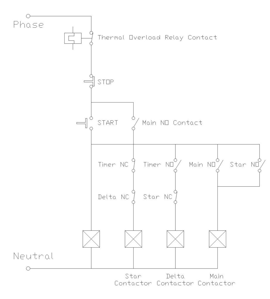
The control circuit manages the sequence of operations in the star delta starter. It uses low voltage (230V AC or 24V DC) to operate the contactor coils and other control devices.
When you press the start button, the control circuit energizes the main contactor coil and the star contactor coil simultaneously. The timer also starts counting at this moment. A holding contact from the main contactor keeps the circuit energized even after you release the start button.
The timer is set for a specific duration usually determined by the time required for the motor to reach about 80% of its rated speed. When this time expires, the timer changes the state of its contacts. The normally closed contact connected to the star contactor opens, de-energizing the star contactor. The normally open contact connected to the delta contactor closes, energizing the delta contactor.
An electrical interlock is provided between the star and delta contactors to prevent both from closing at the same time. If both contactors close together, it creates a short circuit between phases. The interlock uses normally closed auxiliary contacts from each contactor in the coil circuit of the other contactor.
6. Transition from Star to Delta
The transition from star to delta is a brief but important moment in the starting sequence. There are two types of transitions: open transition and closed transition.
Open Transition: In this method, there is a brief period when neither star nor delta contactor is closed. The motor is disconnected from the supply for a fraction of a second. During this period, the motor continues to rotate due to inertia, but the magnetic field collapses. When the delta contactor closes, the collapsing field can cause a high transient current, sometimes higher than direct starting.
Closed Transition: In this method, resistors or reactors are connected in the circuit during the changeover. The motor is never completely disconnected from the supply. This reduces the transient current during changeover. Closed transition starters are more expensive but provide smoother starting.
Most industrial star delta starters use open transition due to lower cost. The transient during changeover is acceptable for most applications. Closed transition starters are used where very smooth starting is required or where the supply system is weak.
7. Starting Time Calculation
The acceleration time during star starting can be determined using:
\( t_{acc} = \frac{J \times \omega_s}{P_{poles}} \times \int_0^{s_{switch}} \frac{ds}{T_{motor}(s) – T_{load}(s)} \)
Where:
- \(omega_s\) = synchronous speed
- \(P_{poles}\) = number of poles
- \(s_{switch}\) = slip at switching point
8. Energy Savings During Starting
The energy consumed during star starting compared to direct delta starting:
\( E_{star} = \frac{E_{delta}}{3} \times t_{star} + E_{delta} \times t_{delta} \)
Where \(t_{star}\) and \(t_{delta}\) represent the time spent in each configuration.
9. Power Factor During Starting
The power factor during star starting is:
\( \cos\phi_{star} = \frac{R_e}{\sqrt{R_e^2 + (X_e/\sqrt{3})^2}} \)
10. Advantages and Disadvantages of Star Delta Starter
10.1 Advantages
The star delta starter offers several benefits that make it a popular choice in industrial applications.
- The starting current is reduced to approximately 33% of the direct starting current. This puts less stress on the electrical supply system and reduces voltage drops.
- The cost of a star delta starter is lower compared to other reduced voltage starting methods like auto-transformer starter or soft starter.
- Maintenance is simple because the components are straightforward. Any electrician with basic training can troubleshoot and repair a star delta starter.
- The starter is reliable and has a long service life when properly sized and maintained. The technology has been proven over many decades of use.
- Energy efficiency during starting is better compared to methods that use resistors to reduce voltage.
- The starter provides automatic changeover without requiring operator intervention.
10.2 Disadvantages
Despite its advantages, the star delta starter has some limitations that must be considered.
- The starting torque is reduced to 33% of the direct starting torque. This makes it unsuitable for applications requiring high starting torque, such as loaded conveyors, crushers, or compressors starting against pressure.
- The motor must have six terminals accessible. The motor must be designed for delta operation at the supply voltage. If the motor is designed for star connection at the supply voltage, star delta starting cannot be used.
- During the transition from star to delta, there is a current spike. In open transition starters, this spike can sometimes be higher than the direct starting current, although it lasts for a very short time.
- The starter requires more cables between the starter and the motor. Instead of three cables, six cables are needed to connect all motor terminals.
- The fixed reduction ratio of 1:3 is not adjustable. Unlike soft starters or variable frequency drives, the starting characteristics cannot be customized.
11. Applications of Star Delta Starter
Star delta starters are used in many industrial and commercial applications where the starting torque requirement is not very high.
- Centrifugal Pumps: Pumps used for water supply, cooling systems, and irrigation start with low load and gradually increase the load as speed increases. Star delta starting is ideal for such applications.
- Fans and Blowers: Industrial fans and blowers for ventilation and air handling start with minimal load and are well-suited for star delta starting.
- Compressors: Unloaded compressors or compressors with unloading valves can be started using star delta starters.
- Machine Tools: Many machine tools like lathes, milling machines, and drilling machines use star delta starters for their main drive motors.
- Conveyors: Empty or lightly loaded conveyors can be started with star delta starters. However, heavily loaded conveyors may require other starting methods.
- Mixers and Agitators: When starting empty or with light materials, these can use star delta starting.
Generally, star delta starters are recommended for motors above 5 HP (or 4 kW) and up to about 100 HP (75 kW), depending on the application requirements and local electrical regulations.
12. Comparison with Alternative Starting Methods
12.1 Comparison with Direct-On-Line (DOL) Starter
The DOL starter is the simplest method of starting a motor. It connects the motor directly to the supply without any current reduction. Let us compare it with the star delta starter.
| Parameter | DOL Starter | Star Delta Starter |
|---|---|---|
| Starting Current | 5-7 times full load current | About 2 times full load current |
| Starting Torque | 100% of direct starting torque | 33% of direct starting torque |
| Number of Contactors | 1 | 3 |
| Cable Requirement | 3 cables to motor | 6 cables to motor |
| Cost | Lower | Higher |
| Complexity | Simple | Moderate |
| Motor Terminals | 3 required | 6 required |
For small motors (below 5 HP), DOL starting is preferred due to simplicity and cost. For larger motors, star delta or other reduced voltage methods are recommended.
12.2 Comparison with Soft Starter
Soft starters use electronic components (thyristors) to gradually increase the voltage applied to the motor. They offer more advanced features than star delta starters.
| Parameter | Star Delta Starter | Soft Starter |
|---|---|---|
| Current Reduction | Fixed at 33% | Adjustable |
| Torque Reduction | Fixed at 33% | Adjustable |
| Transition | Stepped (star to delta) | Smooth and gradual |
| Cost | Lower | Higher |
| Starting Customization | Not possible | Possible |
| Soft Stop Feature | Not available | Available |
| Motor Cables | 6 required | 3 required |
Soft starters are preferred when smooth starting is required or when the starting characteristics need to be adjusted for different load conditions.
13. Maintenance of Star Delta Starter
Regular maintenance keeps the star delta starter in good working condition and prevents unexpected breakdowns.
Weekly Checks:
Observe the starter during operation. Listen for any unusual sounds like buzzing or humming from contactors. Check indicator lamps for proper operation.
Monthly Checks:
Inspect the contactor contacts for signs of burning or pitting. Clean dust and debris from the starter enclosure. Check the tightness of all electrical connections.
Quarterly Checks:
Test the overload relay by simulating an overload condition. Check the timer operation and accuracy. Inspect the cable insulation for any damage.
Annual Checks:
Replace contactor contacts if worn beyond acceptable limits. Check and replace the timer if it shows signs of malfunction. Verify the calibration of the overload relay. Check the condition of fuses and circuit breakers.
14. Selection Criteria for Star Delta Starter
When selecting a star delta starter, consider the following factors.
- Motor Rating: The starter must match the motor’s power rating and full load current. Check the motor nameplate for these details.
- Supply Voltage: The starter should be rated for the supply voltage available. Common voltages are 415V, 440V, or 380V for power circuits and 230V or 110V for control circuits.
- Motor Configuration: Verify that the motor is suitable for star delta starting. It must have six accessible terminals and be rated for delta connection at the supply voltage.
- Load Characteristics: Check if the load allows starting with reduced torque. The load should not require more than 33% of the motor’s direct starting torque during acceleration.
- Starting Frequency: If the motor starts frequently, consider using heavy-duty contactors rated for higher operational cycles.
- Environmental Conditions: Select an enclosure suitable for the installation environment. IP ratings indicate protection against dust and water.
- Standards Compliance: Ensure the starter complies with relevant standards like IEC, IS, or other applicable standards in your region.
15. Conclusion
The star delta starter is a reliable and economical method for starting three-phase induction motors. It reduces the starting current to about one-third of the direct starting current by first connecting the motor in star and then in delta configuration. While it reduces both starting current and starting torque by the same ratio, it is suitable for many applications where the load allows starting with reduced torque.