In power system protection, relays are used to detect faults and send trip signals to circuit breakers. But not every relay in a coordinated protection scheme should operate at the same speed.. Some relays need to wait a little longer before tripping while others need to act faster. This is where the Time Multiplier Setting (TMS), also known as the Time Dial Setting (TDS), comes into play.
TMS is a setting on overcurrent relays that controls how long the relay will take to operate once the fault current exceeds the pickup value. By adjusting the TMS, protection engineers can create a coordinated sequence of relay operations across a power network. This means that the relay closest to the fault operates first, and the upstream relays act as backup with increasing time delays. Without proper TMS adjustment, relays may operate out of sequence, leading to unnecessary power outages in healthy sections of the network.
In this technical guide, we will discuss what Time Multiplier Setting (TMS) is, why TMS is needed, characteristics curves, how to calculate TMS, relationship between TMS, Plug Setting, and PSM, TMS coordination procedure with practical examples.
1. What Exactly Is Time Multiplier Setting (TMS)?
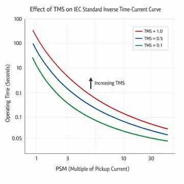
The Time Multiplier Setting is a numerical value assigned to an inverse definite minimum time (IDMT) overcurrent relay. It determines the actual operating time of the relay for a given level of fault current. The TMS value is a multiplier applied to the relay’s characteristic curve. When you increase the TMS, the relay takes more time to trip. When you decrease it, the relay trips faster.
TMS values range from 0.025 to 1.0 on most relays, though this range may vary depending on the relay manufacturer. The value of TMS does not change the shape of the time-current characteristic curve. Instead, increasing TMS shifts the curve upward (longer operating times), while decreasing TMS shifts it downward (shorter operating times). A TMS of 1.0 gives the maximum operating time, while a lower TMS gives a shorter operating time for the same fault current.
2. Why Is TMS Needed in Power System Protection?
Power systems are designed with multiple levels of protection. Each level corresponds to a different zone in the network. For example, in a radial distribution system, there may be several relays installed at different substations along the feeder. If a fault occurs near the end of the feeder, the relay closest to the fault should operate first. If that relay fails, the next upstream relay should operate as a backup.
To achieve this coordination, each upstream relay is given a slightly higher operating time than the one downstream. The TMS is the tool that allows engineers to set these graded time delays. Without TMS, all relays with the same current setting and characteristic curve would operate at the same time, making selective coordination impossible.
The grading margin between successive relays is usually kept between 0.2 to 0.5 seconds, depending on the type of relay (electromechanical or numerical) and the circuit breaker operating time.
3. How TMS Works with Relay Characteristic Curves
IDMT relays follow standardized time-current characteristic curves defined by IEC 60255 and IEEE C37.112. The most common characteristic curves are:
- Standard Inverse (SI)
- Very Inverse (VI)
- Extremely Inverse (EI)
- Long Time Inverse
Each of these curves is described by a mathematical equation that relates the operating time of the relay to the ratio of fault current to the pickup current. This ratio is called the Plug Setting Multiplier (PSM).
The general formula for the operating time of an IDMT relay is:
\(t = \text{TMS} \times [\frac{K}{M^\alpha − 1}]\)
Where:
- t = operating time of the relay in seconds
- TMS = Time Multiplier Setting
- K and \(\alpha\) = constants that depend on the type of curve
- M = ratio of fault current to pickup current (PSM)
For the IEC Standard Inverse curve, \(K = 0.14\) and \(\alpha = 0.02\)
So the formula becomes:
\(t = \text{TMS}\times [\frac{0.14}{M^{0.02} − 1}]\)
From this formula, you can see that TMS acts as a direct multiplier of the operating time. If you double the TMS, the operating time doubles.
4. IEC and IEEE Curve Constants
Here is a table showing the constants for different IEC and IEEE curve types:
4.1 IEC Curves (IEC 60255)
| Curve Type | K | α |
|---|---|---|
| Standard Inverse | 0.14 | 0.02 |
| Very Inverse | 13.5 | 1.0 |
| Extremely Inverse | 80.0 | 2.0 |
| Long Time Inverse | 120.0 | 1.0 |
4.2 IEEE Curves (IEEE C37.112)
| Curve Type | A | B | p |
|---|---|---|---|
| Moderately Inverse | 0.0515 | 0.1140 | 0.02 |
| Very Inverse | 19.61 | 0.491 | 2.0 |
| Extremely Inverse | 28.2 | 0.1217 | 2.0 |
For IEEE curves, the operating time formula is slightly different:
\(t = \text{TDS} \times [\frac{A}{M^p − 1} + B]\)
In the IEEE standard, TDS (Time Dial Setting) is used instead of TMS, but both terms refer to the same concept.
5. How to Calculate TMS: Step-by-Step Example
Let us work through a practical example to make this concept clear.
5.1 Problem Statement
A radial feeder has two relays: Relay A (downstream, closer to the load) and Relay B (upstream, closer to the source). Both relays use IEC Standard Inverse characteristics. The fault current at the location of Relay A is 5000 A. The CT ratio for both relays is 500/1. The plug setting (pickup current setting) for both relays is 100% (i.e., 1A secondary).
We want Relay A to operate with a TMS of 0.1 and then determine the TMS for Relay B so that it operates 0.4 seconds after Relay A.
Step 1: Calculate PSM for Relay A
Fault current on the secondary side \(= \frac{5000}{500} = 10 A\)
Pickup current = 1 A (100% of CT secondary)
PSM \(= \frac{10}{1} = 10\)
Step 2: Calculate Operating Time of Relay A
Using the IEC Standard Inverse formula:
\(t_A = 0.1 \times [\frac{0.14}{10^{0.02} − 1}]\)
First, calculate 10^0.02:
\(10^{0.02} = e^{(0.02 \times \ln (10))} = e^{(0.02 \times 2.3026)} = e^{0.04605} ≈ 1.04713\)
So, \(10^{0.02} − 1 = 0.04713\)
\(t_A = 0.1 \times \frac{0.14}{0.04713} = 0.1 \times 2.97 = 0.297\, \text{seconds}\)
Step 3: Determine Required Operating Time for Relay B
\(t_B = t_A + \text{grading margin} = 0.297 + 0.4 = 0.697\, \text{seconds}\)
Step 4: Calculate TMS for Relay B
Assuming Relay B sees the same fault current (since it is also on the same feeder) and has the same PSM of 10:
\(0.697 = \text{TMS}_B \times \frac{0.14}{0.04713}\)
\(0.697 = \text{TMS}_B \times 2.97\)
\(\text{TMS}_B = \frac{0.697}{2.97} = 0.2347\)
So, Relay B should be set with a TMS of approximately 0.25 (rounding to the nearest available setting on the relay).
6. Relationship Between TMS, Plug Setting, and PSM
The three main settings of an IDMT overcurrent relay are:
- Plug Setting (PS) — This sets the pickup current. It determines the minimum current at which the relay starts to operate.
- Plug Setting Multiplier (PSM) — This is the ratio of actual fault current (referred to secondary) to the plug setting. It indicates how many times the fault current exceeds the pickup value.
- Time Multiplier Setting (TMS) — This adjusts the operating time for a given PSM.
These three parameters work together. The plug setting decides “at what current the relay begins to respond”. The PSM tells us “how severe the fault is compared to the pickup”. And the TMS tells us “how fast or slow the relay will respond for that severity”.
Changing the plug setting changes the PSM for the same fault current. Changing the PSM changes the base operating time from the characteristic curve. And the TMS scales that base time to give the final operating time.
7. TMS in Electromechanical vs. Numerical Relays
7.1 Electromechanical Relays
In older electromechanical IDMT relays (such as the famous CDG series), the TMS is adjusted using a mechanical dial. This dial changes the distance that the relay disc needs to travel before making contact. A higher TMS means the disc has to rotate more before closing the trip contact, resulting in a longer operating time.
In these relays, the TMS is usually adjustable in discrete steps from 0.05 to 1.0. The accuracy of the TMS depends on the mechanical precision of the relay components.
7.2 Numerical Relays
In modern numerical (digital) relays, the TMS is set through software or the relay’s front panel interface. Numerical relays offer much finer resolution for TMS settings. For example, you can set a TMS of 0.175 or 0.225, which would not be possible on an electromechanical relay.
Numerical relays also allow the user to choose from multiple characteristic curves and even define custom curves. The TMS in numerical relays is calculated by an internal processor, which makes the operating time more accurate and repeatable compared to electromechanical relays.
8. Grading Margin and TMS Coordination
When coordinating relays in a series, the grading margin (also called the coordination time interval or CTI) is the time difference between the operating times of two successive relays for the same fault current. The grading margin accounts for the following:
- Circuit breaker operating time (usually 50–100 ms for modern breakers)
- Relay overshoot time (the time the relay takes to reset after the fault is cleared — more relevant for electromechanical relays, around 50 ms)
- Safety margin (an additional buffer, usually 50–100 ms)
- CT and relay errors
For electromechanical relays, a grading margin of 0.4 to 0.5 seconds is commonly used. For numerical relays, this can be reduced to 0.2 to 0.3 seconds because of their faster response and negligible overshoot.
The TMS of each relay in the grading chain is selected so that the required grading margin is maintained at the maximum fault current level seen by both relays.
9. Step-by-Step Procedure for TMS Coordination
Here is the general procedure followed by protection engineers to set TMS values in a radial system:
- Identify all relays in the network and their locations.
- Determine the maximum fault current at each relay location using short-circuit analysis.
- Set the plug setting for each relay based on the maximum load current and the minimum fault current at each location.
- Start from the relay closest to the fault (the most downstream relay). Assign the lowest possible TMS to this relay so that it operates as fast as possible.
- Calculate the operating time of this relay for the maximum fault current.
- Add the grading margin to get the required operating time for the next upstream relay.
- Calculate the TMS for the upstream relay using the relay’s characteristic equation.
- Repeat steps 6 and 7 for each successive relay moving upstream toward the source.
- Verify the coordination by plotting all relay curves on a single time-current graph and checking that no curves cross within the fault current range.
10. Practical Considerations While Setting TMS
10.1 Avoid Very Low TMS Values
While a very low TMS gives fast operating times, it can lead to problems. If the TMS is too low, the relay may operate for transient overcurrents such as motor starting currents or transformer inrush currents. A minimum TMS of 0.05 is generally recommended.
10.2 Avoid Very High TMS Values
A very high TMS results in long operating times, which means the fault will persist for a longer duration. This can cause equipment damage, thermal stress on conductors, and arc flash hazards. The TMS should be kept as low as possible while still maintaining proper coordination.
10.3 Check at Multiple Fault Levels
Coordination should be verified not only at the maximum fault current but also at reduced fault levels. Sometimes, relay curves may cross at lower fault currents even though they are properly coordinated at the maximum level. This is especially a concern when relays use different characteristic curves.
10.4 Account for CT Errors
CT saturation at high fault currents can affect the actual current seen by the relay. This should be considered when selecting TMS values, especially for relays close to high-fault-level busbars.
11. TMS in Different Types of Overcurrent Protection
11.1 Phase Overcurrent Protection
TMS is commonly set for phase overcurrent elements to protect against three-phase and phase-to-phase faults. The plug setting and TMS are chosen based on the maximum load current and the maximum phase fault current at the relay location.
11.2 Earth Fault Protection
Earth fault relays also use TMS settings. Since earth fault currents are usually lower than phase fault currents, the plug setting for earth fault relays is set lower (often 10–40% of CT rating). The TMS for earth fault protection is set independently from the phase overcurrent TMS to allow proper coordination of earth fault relays in the network.
11.3 Directional Overcurrent Protection
In ring main or parallel feeder systems, directional overcurrent relays are used. These relays use the same IDMT characteristics and TMS settings but only operate for faults in a specific direction. The TMS coordination in such systems is more complex and requires careful analysis of fault current magnitudes and directions for faults at different locations.
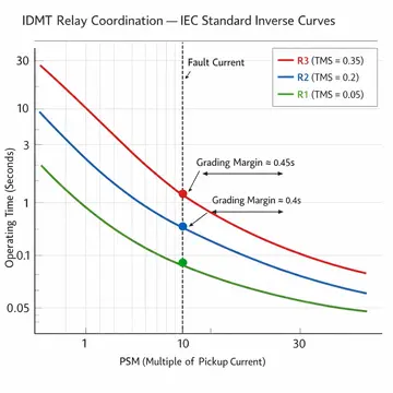
12. Example: Three-Relay Coordination in a Radial System
Consider a radial system with three relays: R1 (most downstream), R2 (middle), and R3 (most upstream). All relays use IEC Standard Inverse characteristics.
| Relay | Fault Current (A) | CT Ratio | Plug Setting | PSM |
|---|---|---|---|---|
| R1 | 4000 | 400/1 | 1.0 A | 10 |
| R2 | 4000 | 400/1 | 1.0 A | 10 |
| R3 | 4000 | 400/1 | 1.0 A | 10 |
(For simplicity, all relays see the same fault current for a fault near R1.)
Step 1: Set TMS for R1 = 0.05 (fastest possible operation)
\(t_{R1} = 0.05 \times [\frac{0.14}{(10^{0.02} − 1)}] = 0.05 \times 2.97 = 0.1485\, \text{seconds}\)
Step 2: Required time for R2 \(= 0.1485 + 0.4 = 0.5485\, \text{seconds}\)
\(\text{TMS}_{R2} = \frac{0.5485}{2.97} = 0.1847\) → Set to 0.2
Actual \(t_{R2} = 0.2 \times 2.97 = 0.594 \, \text{seconds}\)
Step 3: Required time for R3 \(= 0.594 + 0.4 = 0.994 \, \text{seconds}\)
\(\text{TMS}_{R3} = \frac{0.994}{2.97} = 0.3347\) → Set to 0.35
Actual \(t_{R3} = 0.35 \times 2.97 = 1.0395 \, \text{seconds}\)
This gives a well-coordinated system where R1 operates first at 0.15 seconds, R2 acts as backup at 0.59 seconds, and R3 provides further backup at 1.04 seconds.
13. Conclusion
The Time Multiplier Setting (TMS) or Time Dial Setting (TDS) is one of the most important parameters in overcurrent relay protection. It directly controls the operating time of IDMT relays and is the primary tool used by engineers to achieve proper relay coordination in power systems.
The TMS acts as a multiplier on the relay’s time-current characteristic curve. A lower TMS means faster operation, and a higher TMS means slower operation. Proper selection of TMS values requires knowledge of fault current levels, relay characteristics, grading margins, and the overall protection philosophy of the power system.
14. Frequently Asked Questions (FAQs)
TMS (Time Multiplier Setting) and TDS (Time Dial Setting) refer to the same parameter. TMS is the term used in the IEC standard (IEC 60255), while TDS is used in the IEEE standard (IEEE C37.112).
The TMS value ranges from 0.025 to 1.0 on most relays. Some numerical relays allow settings as fine as 0.01 increments. Electromechanical relays have discrete steps, often in increments of 0.05.
If the TMS is set too low, the relay may operate too fast and trip for normal transient conditions such as motor starting or transformer energization. This can cause nuisance tripping and unnecessary power interruptions.
A high TMS means the relay takes a longer time to operate during a fault. This exposes the power system equipment to prolonged fault currents, which can lead to thermal damage to cables, transformers, and switchgear.
TMS is the primary parameter used to achieve time grading between relays in a series. Each upstream relay is assigned a higher TMS (or a TMS that results in a longer operating time) than the downstream relay, so that the downstream relay always operates first for a fault in its zone.
Two relays can have the same TMS if they are protecting different feeders that are not in series. However, relays in the same coordination chain should not have the same TMS, as this would result in simultaneous operation.
No. The TMS has no effect on the pickup current. The pickup current is determined by the plug setting (current setting). TMS only affects the time delay after the current exceeds the pickup value.
In numerical relays, TMS is entered through the relay’s HMI (Human-Machine Interface) or through configuration software.
No. TMS is specific to inverse time overcurrent relays (IDMT relays). Definite time overcurrent relays have a fixed time delay that is set directly and does not depend on the magnitude of the fault current.