Transformer differential protection is the most sensitive and selective form of protection available for transformers in modern electrical power systems. When properly designed and configured, differential relays can detect even minor faults within the transformer protection zone while remaining completely stable for faults occurring outside the zone.
In this technical guide we will discuss the principles of transformer differential protection, walk you through detailed relay setting calculations, explore discrimination techniques that distinguish inrush current from real faults, and provide practical testing procedures.
What Is Transformer Differential Protection?
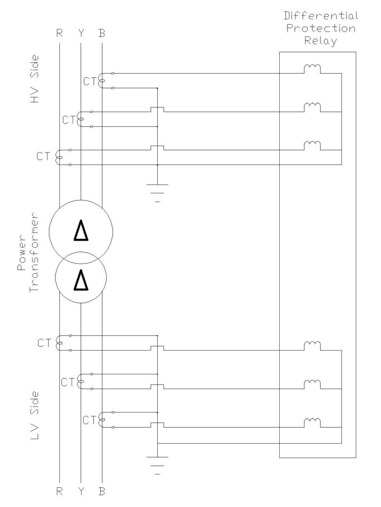
Transformer differential protection is based on a fundamental principle: under normal operation or external fault conditions, the current entering a transformer approximately equals the current leaving it. If a large unbalance in current exists between the primary and secondary sides of a transformer, it indicates an internal fault that requires immediate disconnection.
The Basic Principle:
\(\text{Under Normal Conditions: } I_{\text{primary}} = I_{\text{secondary}} \times \frac{V_{\text{primary}}}{V_{\text{secondary}}}\)
During Internal Fault:
\(\text{Differential Current (I}_{\text{diff}}\text{) = } I_{\text{in}} – I_{\text{out}}\)
When a differential current exists, the relay operates and sends a trip signal to circuit breakers on both sides of the transformer, isolating it in less than one cycle, typically 40-100 milliseconds. This fast response minimizes fault damage, limits heat generation, and prevents oil decomposition.
Differential protection is selective because it only responds to faults within its defined protection zone (between the two current transformers). Faults occurring outside this zone even on the secondary side just beyond the CT do not produce sufficient differential current to trip the relay.
Why Differential Protection for Transformers?
Transformers, especially those rated 10 MVA and above, require fast, sensitive primary protection. Differential protection offers several critical advantages:
- High Sensitivity – Can detect faults as small as 0.2 pu (20% of rated current)
- Selectivity – Responds only to internal faults, ignoring external faults
- Speed – Clears faults in less than one cycle (20 milliseconds at 50 Hz)
- No Intentional Time Delay – Unlike overcurrent relays, differential operates instantaneously
- Backup for Buchholz Relay – Catches faults the Buchholz relay may miss
- Turn-to-Turn Fault Detection – Can detect winding-to-winding short circuits
Types of Transformer Faults Detected by Differential Protection
| Fault Type | Detection Time | Typical Fault Current | Relay Element Used |
|---|---|---|---|
| Phase-to-Phase Short Circuit | Instantaneous (< 100 ms) | 5-50 pu | 87T (Restrained) or 87H (High Set) |
| Phase-to-Ground Short Circuit | Instantaneous to 1 cycle | 1-20 pu | 87G (Ground Differential) |
| Turn-to-Turn Winding Fault | Delayed (depends on severity) | 0.1-0.5 pu | 87 with high sensitivity |
| Core Faults/Circulating Currents | Several cycles to minutes | 0.05-0.2 pu | Dedicated turn-to-turn protection |
| Bushing Flashover | Instantaneous | 3-15 pu | 87H (High Set) |
| Winding Insulation Breakdown | Instantaneous to 1 cycle | 3-30 pu | 87T + 87H |
| Lead Connection Failures | Instantaneous | 1-5 pu | 87T |
| Tap Changer Faults | Delayed | 0.2-1 pu | 87T/87G |
Percentage Biased Differential Relay: Operating Principle
The most widely used differential relay configuration is the percentage biased (or percentage restraint) differential relay. This relay compares the magnitude of differential current against a percentage of the through current (restraint or bias current).
Operating Characteristic Formula
The percentage biased relay operates according to:
\(\text{If } I_{\text{diff}} > I_{\text{pickup}} + K \times I_{\text{bias}}\)
\(\text{Then TRIP (where K is slope percentage in per unit)}\)
Where:
- \((I_{\text{diff}})\) = Differential current (magnitude of current difference)
- \((I_{\text{pickup}})\) = Minimum pickup setting (typically 0.2-0.3 pu)
- \((I_{\text{bias}})\) = Bias current = Average of currents entering and leaving the zone
- \((K)\) = Slope percentage (typically 15-30% for first slope)
Dual-Slope Operating Characteristic
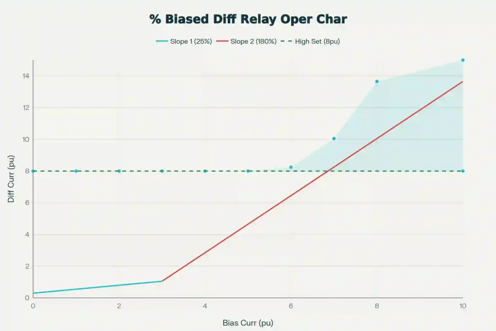
Modern differential relays use a dual-slope characteristic to provide both high sensitivity and high stability:
- Slope 1 (Low Current Region): Steep slope (15-30%) for high sensitivity during internal faults with low through-fault currents.
- Slope 2 (High Current Region): Shallow slope (100-200%) for high stability during external faults with high through-fault currents.
The transition between slopes typically occurs at 3-6 times rated current.
Calculating Differential Relay Settings: Practical Example
Let’s work through a complete example showing how to calculate settings for a real transformer:
Given Data:
- Transformer: 315 MVA, 220 kV/110 kV, Delta-Wye connected
- Primary CT: 800:5 (CTR = 160)
- Secondary CT: 1200:5 (CTR = 240)
- Transformer Impedance: 10%
- Exciting Current: 0.5%
Step 1: Calculate Full Load Currents
Primary Full Load Current: \((I_1 = \frac{315 \times 1000}{\sqrt{3} \times 220} = 826.66 \text{ A})\)
Secondary Full Load Current: \((I_2 = \frac{315 \times 1000}{\sqrt{3} \times 110} = 1653.32 \text{ A})\)
Step 2: Calculate CT Secondary Currents
Primary CT Secondary: \((I_{1,\text{ct}} = \frac{826.66}{160} = 5.17 \text{ A})\)
Secondary CT Secondary: \((I_{2,\text{ct}} = \frac{1653.32}{240} = 6.89 \text{ A})\)
Step 3: Calculate Pickup Setting
The pickup setting should be above the exciting current (0.5% of primary FLC):
Exciting Current: \((I_{\text{ex}} = 0.5\% \times \frac{826.66}{160} = 0.026 \text{ A (CT secondary)})\)
Recommended Pickup: 20% of primary FLC = \((\frac{20\% \times 826.66}{160} = 1.033 \text{ A})\)
This provides approximately 40:1 margin above exciting current—sufficient for stable operation.
Step 4: Calculate Slope Setting
Error Sources (Worst Case):
- CT Ratio Error: ±1.5%
- Tap Variation: ±10%
- Relay Accuracy: ±2%
- Safety Margin: 10%
Total Error = 1.5 + 10 + 2 + 10 = 23.5%
Required Slope ≥ 25% (rounded up to nearest standard value)
Discriminating Between Inrush Current and Internal Faults
One of the greatest challenges in transformer differential protection is distinguishing between magnetizing inrush current (which should NOT trip the relay) and internal fault current (which MUST trip the relay immediately).
| Characteristic | Magnetizing Inrush | Internal Fault Current |
|---|---|---|
| Duration | 0.1-1.0 seconds | Continuous until cleared |
| Magnitude Trend | Decays exponentially | Constant or increasing |
| Waveform Shape | Highly distorted, peaky | Sinusoidal or slightly distorted |
| 2nd Harmonic Content | 30-70% of fundamental | < 20% of fundamental |
| 5th Harmonic Content | 10-30% of fundamental | < 15% of fundamental |
| DC Component | Strong (decreases with time) | Minimal or absent |
| Appears on Both Sides | Only on energized side (initial) | Yes (appears on both sides) |
| Symmetry | Asymmetrical, unidirectional peaks | Symmetrical, bidirectional |
| Detection Method | Harmonic restraint/blocking | Biased differential slope |
| Typical Relay Response | Blocked/Restrained (no trip) | Trip (instantaneous or delayed) |
Harmonic Restraint and Blocking Methods
1. Second Harmonic Restraint
The most common discrimination technique. High 2nd harmonic content (present in inrush) causes the relay to raise its pickup threshold or reduce its sensitivity. The relay continuously monitors the ratio of 2nd harmonic to fundamental:
\(\text{Harmonic Ratio} = \frac{I_{\text{2nd harmonic}}}{I_{\text{fundamental}}} \times 100\%\)
If this ratio exceeds a threshold (typically 15-30%), the pickup is increased or operation is delayed, allowing inrush current to pass without tripping while still catching internal faults.
2. Second Harmonic Blocking
An alternative method where a separate blocking relay is activated by the 2nd harmonic component. Its contacts are in series with the differential relay operating coil, blocking trip during inrush events.
3. Fifth Harmonic Blocking
Used to prevent trips during transformer overexcitation (V/Hz overstress). When the 5th harmonic content exceeds a threshold (typically 25-40%), operation is blocked.
Current Transformer Saturation and Its Effects
Current transformer saturation is a critical phenomenon that affects differential relay operation, particularly during external faults with high primary currents. When a CT saturates, its secondary current becomes distorted and nonlinear, potentially causing false differential currents.
| CT Parameter | Impact on Differential | Mitigation |
|---|---|---|
| Ratio Error (±0.1-3%) | Creates false differential current | Use matching CTs, slope ≥ 25% |
| Saturation | Unequal saturation causes differential during external faults | High saturation voltage CTs, harmonic restraint |
| Remanent Flux (50-80% rated) | Increases saturation for subsequent faults | Controlled de-energization, demagnetization |
| Phase Angle Error (0-30 min) | Vector addition errors | Numerical relay compensation |
| DC Offset | Distorted secondary waveform | Relay filters DC component automatically |
Transient Bias Technique: Modern numerical relays use an advanced algorithm that temporarily increases the operating threshold when CT saturation is detected. This provides high stability during external faults while maintaining fast tripping for true internal faults, even in the presence of harmonics from CT saturation.
High Set Element: Unrestrained Differential Protection
In addition to the biased differential element (87T), modern relays include an unrestrained high-set element (87H) that provides instantaneous tripping for severe internal faults:
High Set Pickup: Typically 8-15 pu of rated current, set above the maximum possible inrush current but below the lowest internal fault magnitude.
Time Delay: Usually 0.5-1.5 cycles to avoid nuisance tripping during inrush.
Purpose: Ensures fast tripping (< 1 cycle) for high-magnitude internal faults even if the biased element is restrained by harmonics from CT saturation.
Ground Differential Protection (87G)
In addition to phase differential protection, transformers with accessible neutral connections may have ground differential protection (87G) that specifically monitors zero-sequence (ground) currents. This element:
- Detects phase-to-ground faults inside the transformer
- Provides additional sensitivity for winding-to-ground insulation faults
- Operates independently of phase balance conditions
- Uses similar percentage-biased characteristics as phase differential
Relay Setting Parameters and Typical Values
| Setting Parameter | Typical Range | Purpose |
|---|---|---|
| Pickup (87T – Restrained) | 0.2-0.3 pu (20-30%) | Covers excitation current, CT errors, tap variation |
| Slope 1 Percentage | 15-30% | Fast tripping for low through-fault currents |
| Slope 2 Breakpoint | 3-6 pu of FLC | Transition to second slope |
| Slope 2 Percentage | 100-200% | Stability for high external fault currents |
| High Set Pickup (87H) | 8-15 pu | Instantaneous tripping for severe internal faults |
| High Set Time Delay | 0.5-1.5 cycles | Prevents nuisance trip during inrush |
| 2nd Harmonic Restraint | 15-30% of fundamental | Blocks operation during magnetizing inrush |
| 5th Harmonic Threshold | 25-40% of fundamental | Blocks operation during overexcitation |
| CT Ratio Correction | Automatic | Accounts for different CT ratios on HV/LV |
| Vector Group Compensation | Delta/Wye configured | Aligns currents based on transformer connection |
Common Misoperation Causes and Solutions
| Issue | Cause | Solution |
|---|---|---|
| False Trip on Transformer Inrush | High 2nd harmonic in inrush current | Enable 2nd harmonic blocking/restraint (15-30%) |
| Failure to Trip on Fault | Over-sensitive pickup setting | Reduce pickup setting or lower slope |
| Nuisance Trip on External Fault | Slope too steep, CT errors underestimated | Increase slope percentage, verify CT errors |
| Trip on Tap Changer Operation | Large differential current from tap change | Coordinate with tap changer control |
| Trip During Overexcitation | High 5th harmonic during V/Hz overstress | Enable 5th harmonic blocking (25-40%) |
| Trip During CT Saturation | Different saturation on HV and LV sides | Use CT saturation detection, increase 2nd harmonic threshold |
| Unequal CT Ratios | Differential current even at no load | Use internal matching CTs or adjust relay settings |
| Vector Group Mismatch | Phase shift not accounted for | Configure relay for delta/wye connection compensation |
Numerical vs. Electromechanical Relays
While this technical guide focuses on modern numerical (microprocessor-based) differential relays, it’s important to understand the advantages:
Numerical Relay Advantages:
- Automatic CT ratio correction without external matching CTs
- Sophisticated harmonic analysis for better inrush discrimination
- Programmable operating characteristics
- Self-diagnostic and self-supervision functions
- Event recording and data storage
- Easy settings modification
- Better accuracy and repeatability
Numerical Relay Setting Steps:
- Enter transformer nameplate data (kVA, voltages, vector group)
- Enter CT data (CTR on HV and LV sides)
- Relay automatically calculates vector compensation
- Enter pickup and slope settings (or use defaults)
- Enable harmonic blocking/restraint features
- Commission and test per procedure
Commissioning and Testing Transformer Differential Relays
Proper relay commissioning ensures reliable protection. The following tests must be performed:
| Test Item | Procedure | Pass Criteria |
|---|---|---|
| Relay Settings Verification | Verify all settings match design calculations | All settings correctly entered |
| Stability Test (No Load) | Inject rated current both sides with same polarity | Relay remains stable (no trip) |
| Pickup Test | Inject differential current above pickup on one side | Relay trips instantaneously |
| Slope Test | Inject currents to plot relay operating characteristic | Operating points match design within ±10% |
| High Set Test | Inject unrestrained current above high set pickup | Relay trips as designed |
| Harmonic Restraint Test (2nd) | Inject fundamental + 2nd harmonic at threshold level | Relay blocks/restrains when 2nd harmonic exceeds threshold |
| Harmonic Blocking Test (5th) | Inject fundamental + 5th harmonic at threshold level | Relay blocks when 5th harmonic exceeds threshold |
| CT Saturation Detection Test | Simulate CT saturation condition with external fault | Relay remains stable during external fault |
| Inrush Current Immunity Test | Apply recorded inrush waveform to relay inputs | Relay does not trip during inrush event |
| Phase Rotation Test | Verify correct trip for each phase combination | Correct phase current measured for each phase |
Testing Equipment: Modern relay testing requires automated test sets such as Omicron, Doble, Schweitzer, or equivalent equipment to inject precise three-phase currents and voltages and verify relay operation.
Best Practices for Transformer Differential Protection
Setting Design
- Perform CT error calculations for both nominal tap and maximum tap positions
- Apply safety margins (typically 10-20%) for all settings
- Coordinate with backup protection (overcurrent relays)
- Document all calculations and design decisions
- Use standard setting templates for consistency
Installation and Configuration
- Ensure correct CT polarity and phasing
- Verify vector group compensation in relay programming
- Use properly sized and labeled wiring
- Maintain low CT secondary burden
- Properly ground and shield relay signal cables
Maintenance and Monitoring
- Perform periodic relay functional tests (every 3-5 years)
- Review event records for potential issues
- Monitor relay diagnostics and alarms
- Update settings if transformer parameters change
- Train personnel on relay operation and testing
Differential Protection for Three-Winding Transformers
Three-winding transformers require an additional restraint winding for the tertiary connection. The operating criterion becomes:
\(\text{If } I_{\text{diff}} > I_{\text{pickup}} + K \times (I_{\text{bias1}} + I_{\text{bias2}} + I_{\text{bias3}})\)
Modern numerical relays handle this automatically through software configuration.
Conclusion
Transformer differential protection represents the fastest and most selective form of primary protection available for large power transformers. By understanding the fundamental principles of percentage biased differential relays, properly calculating pickup and slope settings, and implementing fault discrimination techniques, you can ensure your transformers are protected against internal faults while maintaining stability for external faults and transient conditions.
Key Takeaways:
- Differential protection detects current imbalance between transformer primary and secondary sides
- Percentage biased characteristic provides both sensitivity and stability through dual slopes
- Harmonic restraint/blocking discriminates inrush from internal faults with 99%+ reliability
- Proper settings require calculation based on CT errors, tap variation, and transformer impedance
- Numerical relays provide advanced features including CT saturation detection and transient bias
- Comprehensive testing is essential for reliable operation during actual fault events
- Coordination with backup protection ensures selective clearing of faults