The transformer Pressure Relief Valve (PRV) relay is one of the most critical safety components in oil-immersed power transformers, serving as the last line of defense against tank rupture and explosion during internal electrical faults.
When an internal arc fault occurs inside a transformer tank, it generates extremely high temperatures that vaporize the insulating oil, creating dangerous pressure waves that can reach destructive levels in milliseconds.
The PRV relay automatically detects this sudden pressure buildup and opens instantly to release the excessive oil, preventing tank explosion, fire hazards, and ensuring the safety of both equipment and personnel.
In this technical guide we will discuss the working principles, types, operation mechanisms, tripping mechanisms, maintenance requirements, and applications of transformer PRV relays with practical examples.
What is a Transformer PRV Relay?
The PRV relay is a mechanical protection device installed on the top or side of transformer tanks that monitors internal oil pressure and automatically initiates a trip signal to disconnect the transformer when unsafe pressure levels are detected.
The electrical protection devices rely on current measurement, however, the PRV relay is a purely mechanical system that responds directly to physical pressure changes within the transformer tank.
The primary purpose of the PRV relay is to protect the transformer from internal arc faults, which are among the most dangerous transformer failures. When internal arcing occurs—such as during turn-to-turn short circuits or winding-to-ground faults—the extremely high temperatures (exceeding 10,000°C) instantly vaporize the transformer insulating oil, creating a rapid pressure wave that can reach dangerous levels in milliseconds.
Without rapid pressure relief, this buildup can rupture the transformer tank, spill hot oil, cause fires, and create explosions. The PRV relay detects this pressure rise and opens a circuit breaker to disconnect the transformer before structural failure occurs.
Historical Background and Standards
The sudden pressure relay concept has been used in transformer protection since the early 20th century, with modern relay protection standards developed through IEEE and IEC specifications.
Today, PRV relays are mandatory protection components on medium to large capacity transformers (typically above 10 MVA) in most power utilities worldwide.
Physical Construction and Components
The PRV relay consists of several essential mechanical components working together to detect and respond to pressure changes:
1. Pressure-Sensing Piston or Diaphragm
The core sensing element is a movable piston or flexible diaphragm exposed directly to the transformer oil pressure. This component is typically made from hardened steel or stainless steel and is precisely engineered to move only when pressure exceeds preset thresholds.
The piston acts as a mechanical transducer, converting pressure (a fluid property) into mechanical displacement that triggers electrical contacts.
2. Spring Mechanism
A calibrated steel spring provides the counterforce to the piston. The spring tension is factory-set and field-adjustable to determine at what pressure the piston will overcome the spring force and move.
The spring constant determines the sensitivity of the relay—a lighter spring creates a more sensitive relay that responds at lower pressures and a stiffer spring requires higher pressure to trigger activation.
Spring tension is typically set between 1.5 to 2.5 bar (150-250 kPa) depending on transformer rating and protection coordination requirements.
3. Electrical Contact Assembly
When the piston moves upward against spring force, it mechanically operates a set of electrical contacts inside the relay enclosure. These contacts are typically arranged as a normally-open (NO) configuration, meaning they are in the open position during normal transformer operation.
When pressure exceeds the threshold, the upward piston movement directly closes these contacts, completing an electrical circuit to the protective system.
4. Protective Housing
The relay components are housed in a weather-resistant stainless steel or aluminum enclosure mounted directly on the transformer tank. This housing protects the internal mechanism from moisture, contaminants, and physical damage while remaining immersed in or in contact with transformer oil at the tank wall.
How PRV Relay Tripping Works
The tripping process of a PRV relay is simple in concept but precisely engineered in execution. Here’s how it works step-by-step during a fault condition:
Stage 1: Pressure Detection
During normal transformer operation, the oil pressure inside the tank remains relatively stable, typically between 0.5 to 1.0 bar (50-100 kPa) depending on ambient temperature and load conditions. The piston or diaphragm remains in its rest position held by the calibrated spring force.
No electrical contacts are engaged, and the relay is essentially dormant.
Stage 2: Rapid Pressure Rise
When an internal fault occurs, particularly an arc fault, the insulating oil at the fault point is vaporized by extreme heat, creating a pressure wave that propagates through the oil.
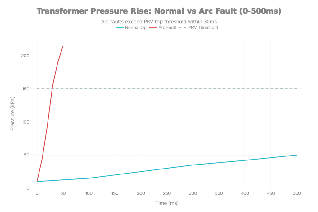
Research on real transformers has shown that internal arc faults can generate pressure spikes reaching 200 kPa or higher in just 20-50 milliseconds. This rate of pressure rise is so rapid that traditional mechanical pressure relief devices cannot respond in time; only the sensitive piston/diaphragm mechanism of the PRV relay can detect it fast enough.
Stage 3: Threshold Crossing
When oil pressure inside the tank exceeds the relay’s set threshold (typically 1.5-2.5 bar or 150-250 kPa), the upward force on the piston overcomes the spring tension. The piston begins to move upward. This movement is not gradual—once the threshold is exceeded, the mechanical system is designed to move decisively and quickly.
Stage 4: Contact Closure and Trip Initiation
As the piston reaches its upper limit of travel (typically 10-20 mm), it mechanically engages the trip contact mechanism. The electrical contacts close, completing a circuit. This closure is mechanical and essentially instantaneous—the time between threshold crossing and contact closure is typically 20-100 milliseconds depending on relay design and calibration.
Stage 5: Circuit Breaker Activation
The closed PRV relay contacts complete a circuit to a tripping coil in the main circuit breaker or an auxiliary protective relay. This sends a signal commanding the circuit breaker to open, isolating the faulted transformer from the power system.
Modern circuit breakers can respond to this signal and fully open within 50-100 milliseconds.
Stage 6: Pressure Release and Reset
Once the transformer is isolated from the source, fault current stops flowing, heat generation stops, and the oil pressure begins to decrease. As pressure drops below the reset threshold (typically 1.0-1.5 bar or 100-150 kPa), the spring force pushes the piston back to its rest position.
The electrical contacts reopen, resetting the relay to its standby state and allowing it to detect subsequent faults.

Total Response Time
The critical measure of PRV relay effectiveness is total response time. Field measurements and research have documented that PRV relays typically achieve complete isolation within 100-200 milliseconds of fault occurrence.
Transformer Oil Release During Very High Pressure Conditions
When internal transformer faults generate extreme pressure conditions exceeding 3.0-4.0 bar (300-400 kPa), the PRV relay’s piston experiences tremendous upward force.
Modern PRV relays incorporate mechanical pressure vents or pop-off valves that activate simultaneously with electrical trip contacts when pressure becomes dangerously high. This dual-action system ensures that as the electrical signal trips the circuit breaker, the mechanical valve simultaneously opens an oil release pathway.
This coordinated action rapidly depressurizes the tank before structural failure occurs.
Advantages and Limitations
Key Advantages of PRV Relays
1. Speed of Response
PRV relays respond in 20-100 milliseconds because they detect mechanical pressure directly, no electrical signal processing is required. Compare this to numerical differential relays that may require 50-200 milliseconds to process signals, perform calculations, and send trip commands. The PRV relay’s mechanical nature makes it inherently fast.
2. Independent Operation
Since the PRV relay is purely mechanical, it operates independently of electrical systems. Even if the transformer’s main protective relays malfunction, the CT (current transformer) circuits fail, or communication links are disrupted, the PRV relay continues to protect the transformer.
3. No False Trips from Inrush
When a transformer is energized (switched on), transient inrush currents flow that can confuse electrical relays. These inrush currents don’t cause rapid pressure rise, so the PRV relay is not affected by this source of false tripping.
4. Simple, Proven Technology
PRV relays have over 100 years of operating experience in transformer protection. The design is straightforward with no electronic components to fail. Utilities trust this proven technology.
5. Cost-Effective
Compared to sophisticated numerical protective relays and instrument transformers, PRV relays are inexpensive. For the level of protection provided, the cost-benefit ratio is excellent.
Limitations and Challenges
1. Cannot Distinguish Fault Types
The PRV relay only knows that pressure has risen—it cannot identify the specific type of fault (turn-to-turn short, ground fault, arcing, etc.). Multiple fault types may generate different pressure signatures that could be valuable diagnostic information, but the simple PRV relay cannot capture this distinction.
2. Limited Diagnostic Information
The PRV relay only provides a binary trip signal—it either operates or it doesn’t. It cannot provide information about pressure magnitude, rise rate, fault location, or timing that would help maintenance engineers diagnose the root cause of the fault. This limits the relay’s value for post-fault analysis.
3. Maintenance and Reliability Concerns
- Spring drift: Over 10-20 years of operation, spring tension gradually changes due to material fatigue and relaxation, causing the trip threshold to drift. Regular calibration testing is needed.
- Oil contamination: Dirt or moisture in the transformer oil can accumulate around the piston, affecting its movement or even causing stiction (static friction) that delays response.
- Mechanical wear: The piston-spring assembly experiences millions of pressure micro-fluctuations, causing gradual wear that reduces reliability.
Typical Settings and Operating Parameters
The operating parameters of a PRV relay must be carefully chosen based on the transformer’s:
- Rated capacity (MVA)
- Voltage class
- Cooling method (ONAN, ONAF, etc.)
- Oil quality and characteristics
- Coordination with other protections
For distribution transformers (10-100 MVA):
- Trip pressure setting: 1.5-2.0 bar (150-200 kPa)
- Reset pressure: 1.0-1.2 bar (100-120 kPa)
- Response time: 20-50 ms
For large power transformers (100-500 MVA):
- Trip pressure setting: 2.0-2.5 bar (200-250 kPa)
- Reset pressure: 1.2-1.5 bar (120-150 kPa)
- Response time: 30-80 ms
For extra-high-voltage transformers (>500 MVA, 345 kV+):
- Trip pressure setting: 2.2-3.0 bar (220-300 kPa)
- Reset pressure: 1.3-1.8 bar (130-180 kPa)
- Response time: 40-100 ms
Larger transformers have higher settings because their larger tank volume means more oil must be vaporized to reach a critical pressure, providing a slightly longer detection window. Higher settings also reduce false trip risk from minor pressure fluctuations.
Testing and Maintenance Procedures
Utilities perform periodic functional tests of PRV relays to verify they still operate correctly:
Visual Inspection (Annual or Semi-Annual):
- Check for oil leaks around the relay
- Verify the housing is not corroded or damaged
- Ensure electrical connections are tight and corrosion-free
- Confirm no water or moisture inside the relay enclosure
Pressure Test (Every 3-5 Years):
- Isolate the transformer from service
- Connect a calibrated pressure source to the relay input
- Slowly increase pressure until the relay trips
- Record the exact trip pressure
- Compare to the design setting (±5-10% variance is typically acceptable)
- Verify the relay resets properly when pressure is reduced
Electrical Test (Every 3-5 Years):
- Verify that relay contact resistance is less than 1 ohm when closed
- Confirm that no leakage current flows when contacts are open
- Test the circuit to the breaker to ensure signal transmission
PRV Relay vs Buchholz Relay
| Feature | PRV (Pressure Relief) Relay | Buchholz Relay |
|---|---|---|
| Detection Principle | Monitors sudden oil pressure rise inside transformer tank | Detects dissolved gas production from insulation degradation and arcing |
| Fault Detection Speed | Ultra-fast: 20-100 milliseconds – responds to pressure spikes instantly | Moderate: 500-2000 milliseconds – requires time for gas bubble collection and accumulation |
| Fault Types Detected | Primarily internal arc faults and sudden pressure-generating faults; responds to any rapid pressure increase regardless of source | Detects incipient faults (slow degradation), turn-to-turn shorts, core faults, oil overheating – responds to gas generation from various fault mechanisms |
| Response Mechanism | Purely mechanical – piston moves directly against spring force to close electrical contacts | Mechanical – floats collect gas in dome chamber; when gas volume exceeds threshold, buoyancy triggers mechanical pendulum that operates trip contacts |
Conclusion
The Transformer PRV Relay remains one of the most valuable and reliable protection devices in power systems, offering unmatched speed of response to the most dangerous transformer faults like internal arc faults that can cause explosions.
The mechanical simplicity of this technology, combined with its independent operation and rapid response time of 20-100 milliseconds makes it an essential component of transformer protection schemes.