The transformer turns ratio is one of the most fundamental concepts in electrical engineering. Whether you are a student learning about transformers for the first time or a practicing engineer designing power systems, knowing how to calculate the turns ratio is a skill you will use repeatedly throughout your career.
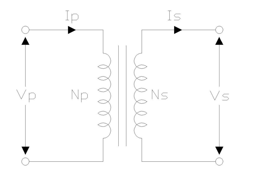
A transformer works on the principle of electromagnetic induction. It transfers electrical energy from one circuit to another through a magnetic core. The number of windings on the primary and secondary sides of the transformer determines how the voltage and current are modified. This relationship between the windings is what we call the transformer turns ratio.
In this technical guide, we will cover everything you need to know about the transformer turns ratio. We will go through the formula, the theory behind it, worked-out examples, and real-world applications.
1. What Is a Transformer Turns Ratio?
The transformer turns ratio is the ratio of the number of turns (windings) on the primary coil to the number of turns on the secondary coil. It is a dimensionless number that tells you how the transformer changes voltage levels between input and output.
If a transformer has 1000 turns on its primary winding and 100 turns on its secondary winding, the turns ratio is 10:1. This means the transformer steps down the voltage by a factor of 10. Conversely, if the primary has 100 turns and the secondary has 1000 turns, the ratio is 1:10, and the transformer steps up the voltage by a factor of 10.
The turns ratio is commonly represented by the letter “a” or expressed as Np:Ns, where Np is the number of primary turns and Ns is the number of secondary turns.
Mathematically, the turns ratio is expressed as:
\( \text{Turns Ratio} (a) = \frac{N_p}{N_s} \)
2. Why Is the Transformer Turns Ratio Important?
The turns ratio governs the entire behavior of a transformer. It dictates the following:
- Voltage Transformation: The turns ratio directly determines the output voltage. Power utilities use transformers with specific turns ratios to step up voltage for long-distance transmission and step it down again for household use.
- Current Transformation: When voltage goes up, current comes down, and vice versa. The turns ratio defines this inverse relationship between primary and secondary current.
- Impedance Matching: In electronics and audio engineering, transformers are used to match impedances between circuits. The impedance transformation depends on the square of the turns ratio.
- Power System Design: Engineers select transformer turns ratios based on the voltage levels required at different stages of the electrical grid. Getting the ratio wrong can lead to equipment damage or inefficient power delivery.
Without a proper grasp of the turns ratio, designing or troubleshooting any transformer-based system becomes extremely difficult.
3. The Transformer Turns Ratio Formula
The basic formula for calculating the transformer turns ratio is straightforward:
\(a = \frac{N_p}{N_s}\)
Where:
- \(a\) = Turns ratio
- \(N_p\) = Number of turns on the primary winding
- \(N_s\) = Number of turns on the secondary winding
Since the voltage across each winding is proportional to the number of turns, we can also write:
\(a = \frac{V_p}{V_s}\)
Where:
- \(V_p\) = Primary voltage
- \(V_s\) = Secondary voltage
And because power is conserved in an ideal transformer (ignoring losses), the current relationship is the inverse:
\(a = \frac{I_s}{I_p}\)
Where:
- \(I_s\) = Secondary current
- \(I_p\) = Primary current
These three expressions are mathematically equivalent for an ideal transformer. You can use whichever form is most convenient based on the information you have available.
3.1 Combined Relationship
Putting it all together, the full relationship looks like this:
\(\frac{N_p}{N_s} = \frac{V_p}{V_s} = \frac{I_s}{I_p} = a\)
This single equation connects turns, voltage, and current. It is the foundation of all transformer calculations.
4. Step-by-Step: How to Calculate Transformer Turns Ratio
Let us walk through the process of calculating the turns ratio in a structured way.
4.1 Step 1: Identify What Information You Have
You might be given the number of turns on each winding, or you might be given the primary and secondary voltages. In some cases, you might only have current values. Identify which quantities are known.
4.2 Step 2: Choose the Appropriate Formula
- If you know the number of turns: \(a = \frac{N_p}{N_s}\)
- If you know the voltages: \(a = \frac{V_p}{V_s}\)
- If you know the currents: \(a = \frac{I_s}{I_p}\)
4.3 Step 3: Plug in the Values and Solve
Substitute your known values into the formula and perform the division.
4.4 Step 4: Interpret the Result
- If \(a > 1\), the transformer is a step-down transformer (voltage decreases from primary to secondary).
- If \(a < 1\), the transformer is a step-up transformer (voltage increases from primary to secondary).
- If \(a = 1\), the transformer is an isolation transformer (voltage remains the same).
4.5 Step 5: Express the Ratio
The result is often expressed as a ratio. For example, if a = 5, you would write the turns ratio as 5:1.
5. Worked Examples
Example 1: Finding Turns Ratio from Winding Turns
A transformer has 500 turns in its primary winding and 1000 turns in its secondary winding. Calculate the turns ratio.
Solution:
\( Turns \,Ratio = \frac{N_p}{N_s} = \frac{500}{1000} = \frac{1}{2} = 1:2 \)
This is a step-up transformer with a turns ratio of 1:2.
Example 2: Calculating Secondary Voltage
A transformer has 1000 turns on the primary winding and 200 turns on the secondary winding. If 250 V is applied to the primary, what is the secondary voltage?
Solution:
First, establish the turns ratio:
\( \frac{N_p}{N_s} = \frac{1000}{200} = 5:1 \)
Using the voltage relationship:
\( \frac{V_p}{V_s} = \frac{N_p}{N_s} \)
\( V_s = V_p \times \frac{N_s}{N_p} = 250 \times \frac{200}{1000} = 50 V \)
The secondary voltage is 50 V, confirming this is a step-down transformer.
Example 3: Finding Primary Turns
A transformer with an output voltage of 2200 V is supplied with 220 V at the primary. If the secondary winding has 2000 turns, calculate the number of turns in the primary winding.
Solution:
Using the voltage-turns relationship:
\( \frac{V_p}{V_s} = \frac{N_p}{N_s} \)
\( N_p = N_s \times \frac{V_p}{V_s} = 2000 \times \frac{220}{2200} = 200\, turns \)
The primary winding has 200 turns.
Example 4: Calculating Secondary Current
A step-down transformer has a turns ratio of 10:1. The primary winding has 1000 turns and draws a current of 2 A. What is the secondary current?
Solution:
Using the current relationship (inverse of turns ratio):
\( \frac{I_p}{I_s} = \frac{N_s}{N_p} \)
\( I_s = I_p \times \frac{N_p}{N_s} = 2 \times \frac{1000}{100} = 20 A \)
The secondary current is 20 A. Notice how the current increased as voltage decreased, maintaining power balance.
Example 5: Complete Transformer Analysis
A transformer has 600 turns on the primary and 120 turns on the secondary. 300 volts is applied to the primary and a current of 40 amps flows in the secondary. Calculate: (a) turns ratio, (b) secondary voltage, and (c) primary current.
Solution:
(a) Turns ratio:
\( \frac{N_p}{N_s} = \frac{600}{120} = 5:1 \)
(b) Secondary voltage:
\( V_s = V_p \times \frac{N_s}{N_p} = 300 \times \frac{120}{600} = 60 V \)
(c) Primary current:
\( I_p = I_s \times \frac{N_s}{N_p} = 40 \times \frac{120}{600} = 8 A \)
We can verify: Power in \(= 300 V × 8 A = 2400 W\), Power out \(= 60 V × 40 A = 2400 W\).
6. Ideal vs. Real Transformers
All the calculations above assume an ideal transformer where there are no energy losses. In reality, transformers have losses due to several factors:
- Copper Losses (I²R Losses): The resistance of the copper wire in the windings causes heat generation. This is the most common source of loss in a transformer.
- Core Losses (Iron Losses): These include hysteresis losses and eddy current losses in the magnetic core. Hysteresis loss occurs because the core material must be magnetized and demagnetized repeatedly. Eddy current losses occur due to circulating currents induced in the core itself.
- Flux Leakage: Not all the magnetic flux generated by the primary winding links with the secondary winding. Some flux escapes into the air, reducing the efficiency of energy transfer.
- Magnetizing Current: A real transformer draws a small magnetizing current even when no load is connected to the secondary. This current is needed to establish the magnetic flux in the core.
Because of these losses, the actual secondary voltage in a real transformer will be slightly less than what the ideal turns ratio formula predicts. The difference is usually small in well-designed transformers. For most calculations and applications, using the ideal formula gives results that are accurate enough for practical purposes.
7. Impedance Transformation and Turns Ratio
One application of the turns ratio that deserves special attention is impedance transformation. Transformers can be used to match the impedance of a source to the impedance of a load. This is particularly common in audio systems, RF circuits, and telecommunications.
The impedance transformation follows a squared relationship:
\(\frac{Z_p}{Z_s} = a^2\)
Or equivalently:
\(Z_p = a^2 \times Z_s\)
Where:
- \(Z_p\) = Impedance seen from the primary side
- \(Z_s\) = Load impedance connected to the secondary side
- \(a\) = Turns ratio
7.1 Example: Impedance Matching
Problem: A speaker has an impedance of 8 ohms. An amplifier works best with a 200-ohm load. What turns ratio is needed for the matching transformer?
Solution:
\(a^2 = \frac{Z_p}{Z_s}\)
\(a^2 = \frac{200}{8}\)
\(a^2 = 25\)
\(a = 5\)
A transformer with a turns ratio of 5:1 is needed.
8. Types of Transformers Based on Turns Ratio
Based on the turns ratio, transformers can be classified into three main types:
8.1 Step-Down Transformer
A step-down transformer has more turns on the primary winding than on the secondary winding. The turns ratio is greater than 1. It reduces the voltage from primary to secondary while increasing the current proportionally.
Common uses: Power distribution (stepping down high transmission voltages to usable levels), battery chargers, and power supplies for electronic devices.
8.2 Step-Up Transformer
A step-up transformer has fewer turns on the primary winding than on the secondary winding. The turns ratio is less than 1. It increases the voltage from primary to secondary while decreasing the current proportionally.
Common uses: Power generation stations (stepping up generator voltage for transmission), CRT displays, and microwave oven circuits.
8.3 Isolation Transformer
An isolation transformer has a turns ratio of 1:1. The voltage and current remain the same on both sides. Its purpose is to electrically isolate two circuits while allowing power to pass between them.
Common uses: Medical equipment, sensitive electronic instruments, and safety applications where galvanic isolation is required.
9. How to Measure Transformer Turns Ratio in Practice
In a laboratory or field setting, you may need to determine the turns ratio of a transformer without having access to its specifications. Here are the common methods:
9.1 Method 1: Voltage Measurement Method
This is the simplest and most widely used method. Apply a known AC voltage to the primary winding and measure the open-circuit voltage at the secondary winding.
\(a = \frac{V_p}{V_s}\)
For example, if you apply 120V to the primary and measure 24V at the secondary, the turns ratio is 5:1.
Important: Always perform this test with no load connected to the secondary. A loaded secondary will give slightly different voltage readings due to voltage drop across the winding resistance.
9.2 Method 2: Using a Turns Ratio Meter (TTR)
A Transformer Turns Ratio (TTR) meter is a specialized instrument designed to measure the turns ratio with high accuracy. It applies a test voltage to the primary winding and measures the induced voltage at the secondary. TTR meters are commonly used in power utilities for testing power transformers during commissioning and maintenance.
TTR testing can also reveal problems like shorted turns, open circuits, or incorrect tap positions on a transformer.
9.3 Method 3: Resistance Measurement (Approximate)
While not a direct method, you can sometimes get a rough estimate of the turns ratio by measuring the DC resistance of the primary and secondary windings. Since the resistance is proportional to the length of wire (and therefore the number of turns), the ratio of resistances gives an approximate indication. However, this method is not accurate because the wire gauge may differ between primary and secondary windings.
10. Turns Ratio in Multi-Winding Transformers
Some transformers have more than two windings. A common example is a transformer with one primary winding and two or more secondary windings. In such cases, the turns ratio is calculated separately for each secondary winding with respect to the primary.
10.1 Example: Multi-Winding Transformer
Problem: A transformer has a primary winding with 1000 turns. It has two secondary windings: Secondary 1 has 200 turns and Secondary 2 has 50 turns. The primary voltage is 500V. Find the voltage at each secondary.
Solution:
For Secondary 1:
\(a_1 = \frac{Np}{N_{s1}} = \frac{1000}{200} = 5\)
\(V_{s1} = \frac{V_p}{a_1} = \frac{500}{5} = 100V\)
For Secondary 2:
\(a_2 = \frac{Np}{N_{s2}} = \frac{1000}{50} = 20\)
\(V_{s2} = \frac{V_p}{a_2} = \frac{500}{20} = 25V\)
Secondary 1 delivers 100V and Secondary 2 delivers 25V.
11. Turns Ratio and Tap Changers
Many power transformers are equipped with tap changers that allow the turns ratio to be adjusted. A tap changer adds or removes turns from a winding, changing the effective number of turns and therefore the output voltage.
There are two types of tap changers:
On-Load Tap Changers (OLTC): These can change the tap position while the transformer is energized and carrying load. They are used in power distribution transformers to regulate voltage as load conditions change throughout the day.
Off-Load (De-Energized) Tap Changers: These require the transformer to be disconnected from the circuit before changing the tap position. They are less expensive and are used where voltage adjustment is needed only occasionally.
For example, a transformer might have taps at +5%, +2.5%, nominal, -2.5%, and -5%. If the nominal turns ratio is 10:1 with a primary voltage of 11kV and secondary voltage of 1.1kV, the +5% tap would increase the primary turns, resulting in a lower secondary voltage. The -5% tap would decrease the primary turns, resulting in a higher secondary voltage.
12. Applications of Transformer Turns Ratio
The turns ratio concept is applied in numerous fields:
- Power Generation and Transmission: Generators produce electricity at 11kV to 25kV. Step-up transformers with low turns ratios (like 1:20) increase the voltage to 132kV, 220kV, or even 765kV for efficient long-distance transmission.
- Power Distribution: Step-down transformers near residential areas bring the voltage down from transmission levels to 120V or 240V for household use.
- Electronic Power Supplies: AC adapters, laptop chargers, and phone chargers all use transformers (or transformer-based designs) to convert mains voltage to the low voltage needed by electronic devices.
- Audio Engineering: Impedance matching transformers are used between microphones, amplifiers, and speakers to maximize power transfer and signal quality.
- Instrumentation: Current transformers (CTs) and potential transformers (PTs) are used to measure high currents and voltages by stepping them down to safe levels that can be read by instruments.
- Welding Equipment: Welding transformers use a very low turns ratio to produce low voltage but very high current needed for welding operations.
13. Summary Table
| Parameter | Formula |
|---|---|
| Turns Ratio | \(a = \frac{N_p}{N_s}\) |
| Voltage Ratio | \(a = \frac{V_p}{V_s}\) |
| Current Ratio | \(a = \frac{I_s}{I_p}\) |
| Impedance Ratio | \(\frac{Z_p}{Z_s} = a^2\) |
| Secondary Voltage | \(V_s = \frac{V_p}{a}\) |
| Secondary Current | \(I_s = I_p \times a\) |
| Secondary Turns | \(N_s = \frac{N_p}{a}\) |
14. Transformer Turns Ratio Calculator
Turns Ratio Calculator
15. Conclusion
Mastering transformer turns ratio calculations is essential for anyone working in electrical engineering. Whether you’re designing power systems, troubleshooting transformer issues, or simply trying to understand how voltage transformation works, the turns ratio provides the fundamental relationship that governs transformer behavior.
16. Frequently Asked Questions (FAQs)
The transformer turns ratio is the ratio of the number of turns on the primary winding to the number of turns on the secondary winding. It determines how the voltage and current are transformed between the input and output sides of the transformer.
You can calculate the turns ratio using the formula: a = Np / Ns, where Np is the number of primary turns and Ns is the number of secondary turns. If you do not know the number of turns, you can also use the voltage ratio: a = Vp / Vs, where Vp is the primary voltage and Vs is the secondary voltage.
A turns ratio of 2:1 means the primary winding has twice as many turns as the secondary winding. This transformer will step down the voltage by half. If you apply 240V to the primary, you will get 120V at the secondary.
Yes. If the secondary has more turns than the primary, the turns ratio will be less than 1 (a fraction or decimal). For example, a transformer with 100 primary turns and 500 secondary turns has a turns ratio of 0.2 or 1:5. This would be a step-up transformer.
Current is inversely related to the turns ratio. If a transformer steps down the voltage (turns ratio greater than 1), the secondary current will be higher than the primary current by the same factor.
The easiest way is to apply a known AC voltage to the primary winding and measure the open-circuit voltage at the secondary. Divide the primary voltage by the secondary voltage to get the turns ratio. For more precise measurements, a TTR (Transformer Turns Ratio) meter can be used.
In an ideal transformer, the turns ratio does not change with load because it is a physical property determined by the number of windings.
For a three-phase transformer, the turns ratio formula is the same: a = Np / Ns. However, the line voltage ratio may differ from the turns ratio depending on the winding configuration (delta or wye). For a delta-wye transformer, the line voltage ratio includes a factor of √3.
The impedance transformation follows the squared relationship because impedance involves both voltage and current. Since voltage transforms directly with the turns ratio and current transforms inversely, the combined effect on impedance (Z = V/I) results in a squared relationship: Zp = a² × Zs.
A transformer with a 1:1 turns ratio is called an isolation transformer. It does not change the voltage or current levels. Its purpose is to provide electrical isolation between two circuits for safety or noise reduction purposes.