Power transformers are among the most expensive and important pieces of equipment in any electrical power system. Protecting them from overheating is a top priority for engineers and maintenance teams across the globe. Two instruments play a central role in transformer thermal protection the Oil Temperature Indicator (OTI) and the Winding Temperature Indicator (WTI). These devices monitor the temperature of transformer oil and windings respectively. They generate alarm and trip signals to prevent permanent damage to the transformer insulation and extend the operational life of the equipment.
Incorrect alarm and trip settings on OTI and WTI devices can lead to either nuisance tripping or undetected overheating. Both situations are dangerous and costly. That is why every protection engineer must know the correct setting values, the standards behind them, and the logic of thermal protection in transformers thoroughly.
In this technical guide, we will discuss everything you need to know about Transformer WTI and OTI Alarm and Trip Settings, including their working principles, types, applications, relay settings, coordination strategies, testing methods, and relevant industry standards. Practical examples are included throughout to help you apply these concepts in real-world scenarios confidently.
1. What Is OTI (Oil Temperature Indicator)?
The Oil Temperature Indicator, commonly abbreviated as OTI, is a device that measures the top oil temperature of a power transformer. It is mounted on the transformer tank, and its sensing bulb is immersed in the top layer of transformer oil inside the main tank. The OTI gives a continuous reading of the oil temperature on a local dial gauge.
The OTI has two or more adjustable contacts inside. These contacts are set at predetermined temperature values. One contact is used for the alarm function and the other is used for the trip function. The alarm contact closes first to warn the operator. If the temperature continues to rise and reaches the trip set point, the trip contact closes to disconnect the transformer from the power system automatically.
2. What Is WTI (Winding Temperature Indicator)?
The Winding Temperature Indicator, abbreviated as WTI, is a device that estimates the hottest spot temperature of the transformer winding. It is important to note that the WTI does not measure the winding temperature directly. Instead, it uses an indirect method to simulate the winding hot spot temperature.
The WTI uses a thermal image technique. A current transformer (CT) is installed on the bushing of the transformer. This CT supplies a proportional current to a small heater coil placed inside the WTI sensing pocket. The sensing pocket is also immersed in the top oil, just like the OTI bulb. The heater coil adds a temperature rise on top of the oil temperature. This combined effect simulates the hot spot temperature of the winding.
The WTI also has adjustable alarm and trip contacts. These contacts are set at higher temperature values compared to OTI because winding temperatures are always higher than oil temperatures during loaded conditions. The WTI is the more important device of the two for protecting the transformer insulation system effectively.
3. Why Temperature Monitoring Matters in Power Transformers
The insulation system of a power transformer is made of cellulose paper and pressboard. These materials are soaked in mineral oil. The aging rate of cellulose insulation doubles for every 6°C to 7°C rise above the rated hot spot temperature. This means even a small and sustained over-temperature condition can reduce the transformer life.
For example, if a transformer rated for a 65°C average winding rise operates continuously at 10°C above its rated hot spot temperature, its insulation life could be cut in half. Over a period of months or years, this accelerated aging weakens the insulation and can cause internal faults, winding failures, and even transformer explosions.
OTI and WTI devices serve as the first line of defense against thermal damage. They provide early warnings to operators and initiate automatic protection actions. Without these devices, a transformer could overheat silently, and the damage would only become apparent after an irreversible failure has occurred already.
Thermal protection of transformers is a requirement under IEEE and IEC standards. All medium and large power transformers are equipped with OTI and WTI as standard practice in the electrical power industry globally.
4. Standard OTI Alarm and Trip Settings
The OTI alarm and trip settings depend on the transformer cooling class, the type of insulation, and the manufacturer’s recommendation. However, the following values are widely accepted in the industry and are based on IEEE C57.91 and IEC 60076 standards:
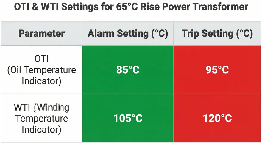
4.1 For ONAN / ONAF Cooled Transformers (65°C Rise Design):
| Function | Temperature Setting |
|---|---|
| OTI Alarm | 85°C |
| OTI Trip | 95°C |
4.2 For OFAF / ODAF Cooled Transformers (65°C Rise Design):
| Function | Temperature Setting |
|---|---|
| OTI Alarm | 85°C to 90°C |
| OTI Trip | 95°C to 100°C |
4.3 For 55°C Rise Design Transformers (Older Designs):
| Function | Temperature Setting |
|---|---|
| OTI Alarm | 75°C |
| OTI Trip | 85°C |
These values are the top oil temperature limits. The alarm setting gives the operator or the control system a warning to take corrective action. Corrective actions include reducing the load, starting additional cooling fans, or investigating the cause of overheating immediately.
The trip setting is the last line of defense. If the oil temperature reaches the trip value, the transformer is disconnected from the network to prevent irreversible insulation damage. The trip signal is sent to the transformer breaker through the protection relay or directly through the trip circuit.
5. Standard WTI Alarm and Trip Settings
The WTI settings are always higher than the OTI settings because the winding hot spot temperature is higher than the top oil temperature. The hot spot gradient depends on the transformer design, load current, and cooling method.
5.1 For ONAN / ONAF Cooled Transformers (65°C Rise Design):
| Function | Temperature Setting |
|---|---|
| WTI Alarm | 105°C |
| WTI Trip | 120°C |
5.2 For OFAF / ODAF Cooled Transformers (65°C Rise Design):
| Function | Temperature Setting |
|---|---|
| WTI Alarm | 105°C to 110°C |
| WTI Trip | 120°C to 130°C |
5.3 For 55°C Rise Design Transformers (Older Designs):
| Function | Temperature Setting |
|---|---|
| WTI Alarm | 95°C |
| WTI Trip | 105°C |
The hot spot temperature limit for standard mineral oil-immersed transformers with thermally upgraded paper insulation is 120°C for normal cyclic loading as per IEEE C57.91. For emergency overloading conditions, the hot spot temperature can be allowed up to 140°C for short durations. However, the trip setting is usually kept at 120°C to 130°C to avoid accelerated aging of the insulation under normal operating conditions.
It is worth noting that some utilities and industrial plants set the WTI trip at 140°C for short-time emergency loading scenarios. This practice must be backed by a proper thermal loading study and the transformer manufacturer’s approval.
6. Practical Example: Calculating OTI and WTI Settings
Let us work through a practical example to illustrate how OTI and WTI settings are determined.
Given Data:
- Transformer Rating: 50 MVA, 132/33 kV, ONAN/ONAF cooling
- Temperature Rise Class: 65°C rise
- Insulation Type: Thermally Upgraded Paper (TUP)
- Maximum Ambient Temperature: 45°C (hot climate region)
- Manufacturer’s Rated Top Oil Rise: 55°C
- Manufacturer’s Rated Hot Spot Rise over Top Oil: 23°C
Step 1: Calculate Expected Top Oil Temperature at Rated Load
Top Oil Temperature = Ambient + Top Oil Rise = 45 + 55 = 100°C
Step 2: Calculate Expected Hot Spot Temperature at Rated Load
Hot Spot Temperature = Top Oil Temperature + Hot Spot Gradient = 100 + 23 = 123°C
Step 3: Set OTI Alarm and Trip
- OTI Alarm = 85°C (standard value, gives early warning before reaching 100°C)
- OTI Trip = 95°C (trips the transformer before the oil reaches the rated limit of 105°C)
Step 4: Set WTI Alarm and Trip
- WTI Alarm = 105°C (standard value, warns before the winding reaches the 120°C limit)
- WTI Trip = 120°C (trips the transformer at the IEEE-recommended hot spot limit)
Step 5: Verify Margins
- Margin between OTI Alarm and OTI Trip = 95 – 85 = 10°C ✓
- Margin between WTI Alarm and WTI Trip = 120 – 105 = 15°C ✓
- These margins provide enough time for the operator to take corrective action after the alarm stage.
7. Additional Contacts on OTI and WTI: Cooling Control
Apart from alarm and trip contacts, both OTI and WTI can have additional contacts for cooling system control. These contacts are used to start or stop cooling fans and oil pumps at defined temperatures.
7.1 Cooling Control Settings
| Function | OTI Setting | WTI Setting |
|---|---|---|
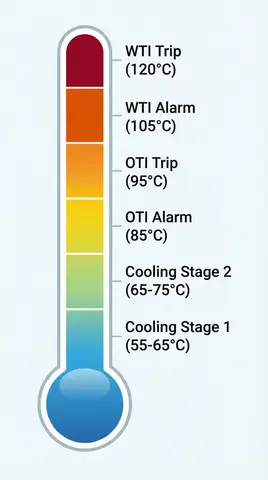
| Start Cooling Stage 1 (Fans ON) | 55°C to 65°C | 75°C to 80°C |
| Start Cooling Stage 2 (Additional Fans/Pumps ON) | 65°C to 75°C | 85°C to 95°C |
| Alarm | 85°C | 105°C |
| Trip | 95°C | 120°C |
The cooling control contacts are set at temperatures lower than the alarm setting. This allows the cooling system to activate before the transformer reaches the alarm level. If the cooling system operates correctly, the temperature should stabilize below the alarm threshold. If the cooling fails and the temperature continues to rise, the alarm and trip contacts will activate sequentially.
8. Factors Affecting OTI and WTI Setting Values
Several factors influence the selection of OTI and WTI alarm and trip settings. A protection engineer must consider all of these factors before finalizing the settings.
8.1 Ambient Temperature
The transformer nameplate ratings are based on a maximum ambient temperature of 40°C and an average ambient temperature of 30°C over 24 hours as per IEEE C57.12.00. In regions with higher ambient temperatures, the OTI and WTI settings may need to be adjusted. For hot climates, some engineers reduce the alarm setting by 5°C to get an earlier warning.
8.2 Cooling System Type
Transformers with forced oil and forced air cooling (OFAF/ODAF) can handle higher oil flow rates. Their OTI and WTI settings may be set slightly higher than naturally cooled (ONAN) transformers. The cooling method directly affects the temperature distribution inside the transformer.
8.3 Insulation Class
Transformers with thermally upgraded paper (TUP) insulation can withstand higher hot spot temperatures compared to standard Kraft paper insulation. TUP insulation allows a continuous hot spot temperature of up to 110°C, and the WTI trip can be set at 120°C to 130°C accordingly.
8.4 Manufacturer Recommendations
Every transformer manufacturer provides recommended OTI and WTI settings in the operation and maintenance manual. These recommendations are based on the specific design of the transformer. Engineers should always check the manufacturer’s data before applying generic setting values.
8.5 Loading Profile
Transformers that experience frequent overloading or cyclic loading patterns require more conservative WTI settings. The cumulative thermal aging effect must be considered during the setting selection process.
9. IEEE and IEC Standards for Transformer Temperature Limits
The alarm and trip settings for OTI and WTI are guided by international standards. The two most referenced standards are:
9.1 IEEE C57.91 – Guide for Loading Mineral-Oil-Immersed Transformers
This standard provides detailed guidance on the thermal loading of transformers. It defines the following temperature limits for 65°C rise transformers:
- Top oil temperature limit (normal life expectancy loading): 105°C
- Winding hot spot temperature limit (normal life expectancy loading): 120°C
- Top oil temperature limit (long-term emergency loading): 110°C
- Winding hot spot temperature limit (long-term emergency loading): 140°C
9.2 IEC 60076-7 – Power Transformers – Loading Guide for Oil-Immersed Transformers
This standard provides similar guidance but uses slightly different terminology. It defines:
- Hot spot temperature limit for normal cyclic loading: 120°C
- Hot spot temperature limit for long-term emergency loading: 130°C
- Top oil temperature limit for normal cyclic loading: 105°C
9.3 IEC 60076-2 – Temperature Rise Tests
This standard specifies the temperature rise test procedures for power transformers. The test results from this standard are used to calibrate the WTI during factory acceptance testing.
Protection engineers should use these standards as the baseline for setting OTI and WTI values. Local utility standards and grid codes may impose additional or stricter requirements in certain regions.
10. Testing and Calibration of OTI and WTI
Testing and calibration of OTI and WTI devices must be performed during factory acceptance testing (FAT), site commissioning, and periodic maintenance. The following procedures are commonly used:
10.1 Dial Gauge Calibration
The OTI and WTI dial gauges are calibrated by immersing the sensing bulb in a temperature-controlled oil bath. The oil bath temperature is gradually increased, and the gauge reading is compared against a reference thermometer. Any deviation is corrected by adjusting the gauge mechanism.
10.2 Contact Setting Verification
Each micro-switch contact is tested to verify that it closes at the correct temperature. The oil bath temperature is slowly raised, and a continuity meter is connected to the contact terminals. The temperature at which the contact closes is recorded and compared against the set point. The contact must close within ±2°C of the set value.
10.3 WTI Heater Circuit Testing
The WTI heater circuit is tested by injecting a known current into the heater coil and measuring the temperature rise above the oil temperature. The injected current corresponds to the rated load current of the transformer (scaled by the CT ratio). The resulting WTI reading should match the calculated hot spot temperature within acceptable tolerance.
10.4 Wiring and Interlock Testing
The alarm and trip wiring from OTI and WTI to the protection relay panel and the control room annunciator must be tested for correctness. A functional test is performed by manually pressing the micro-switch contacts and verifying that the alarm appears on the SCADA system and the trip signal reaches the breaker trip coil successfully.
10.5 Periodic Maintenance Testing
OTI and WTI devices should be tested at least once every two years as part of the transformer preventive maintenance program. The dial gauge accuracy, contact settings, heater coil resistance, and wiring integrity should all be checked during routine maintenance inspections.
11. Common Mistakes in OTI and WTI Settings
Even experienced engineers sometimes make errors in OTI and WTI settings. Here are the most common mistakes to avoid:
1. Setting OTI and WTI values too close together: If the alarm and trip settings are only 3°C to 5°C apart, the operator may not have enough time to respond before the trip occurs. A minimum gap of 10°C between alarm and trip is recommended.
2. Ignoring ambient temperature conditions: Using standard setting values without considering the local ambient temperature can lead to premature tripping in hot climates or delayed protection in cold climates.
3. Not verifying WTI heater calibration: If the WTI heater coil is not calibrated properly, the WTI reading will be inaccurate. This can result in either under-protection or over-protection of the transformer winding.
4. Incorrect CT ratio for WTI heater: Using a wrong CT ratio for the WTI heater circuit will cause incorrect simulation of the hot spot temperature. The CT ratio must match the manufacturer’s specification exactly.
5. Not testing contacts after setting adjustment: After changing the OTI or WTI set points, a functional test must be performed to confirm that the contacts close at the new values. Skipping this test is a frequent oversight.
6. Disabling the trip function permanently: Some operators disable the WTI trip to avoid nuisance tripping during peak load periods. This practice leaves the transformer without thermal trip protection and should never be done without a documented risk assessment.
12. Summary of Recommended OTI and WTI Settings
For quick reference, here is a consolidated summary of the recommended settings:
| Device | Function | 65°C Rise Transformer | 55°C Rise Transformer |
|---|---|---|---|
| OTI | Cooling Stage 1 Start | 55°C – 65°C | 45°C – 55°C |
| OTI | Cooling Stage 2 Start | 65°C – 75°C | 55°C – 65°C |
| OTI | Alarm | 85°C | 75°C |
| OTI | Trip | 95°C | 85°C |
| WTI | Cooling Stage 2 Start | 85°C – 95°C | 75°C – 85°C |
| WTI | Alarm | 105°C | 95°C |
| WTI | Trip | 120°C | 105°C |
These values serve as a general guideline. Always refer to the transformer manufacturer’s documentation and applicable local standards before finalizing the settings for any specific installation.
13. Conclusion
Transformer WTI and OTI alarm and trip settings are a fundamental part of power transformer protection. The OTI monitors the top oil temperature directly, and the WTI simulates the winding hot spot temperature using the thermal image method. Both devices work together to provide staged thermal protection starting with cooling activation, followed by an alarm, and finally a trip if the temperature continues to rise.
The correct selection of alarm and trip values depends on the transformer’s thermal design, insulation class, cooling type, and ambient conditions. IEEE C57.91 and IEC 60076 standards provide the baseline temperature limits that guide the setting process. Regular testing and calibration of OTI and WTI devices are necessary to maintain the accuracy and reliability of the thermal protection scheme.
14. Frequently Asked Questions (FAQs)
OTI measures the top oil temperature of the transformer directly. WTI simulates the winding hot spot temperature using a heating element fed by a current transformer. The WTI reading is always higher than the OTI reading during loaded conditions because the winding temperature is higher than the oil temperature.
The standard OTI alarm setting is 85°C, and the standard OTI trip setting is 95°C for a 65°C rise oil-immersed power transformer.
The standard WTI alarm setting is 105°C, and the standard WTI trip setting is 120°C for a 65°C rise transformer with thermally upgraded paper insulation.
OTI and WTI devices should be tested and calibrated during factory acceptance testing, site commissioning, and at least once every two years during routine preventive maintenance of the transformer.
Some utilities allow the WTI trip to be set at 140°C for short-term emergency loading conditions as per IEEE C57.91. However, this must be approved by the transformer manufacturer and backed by a thermal loading study.
If the trip contact fails, the transformer will continue to operate at dangerous temperatures. This can cause severe insulation damage and may lead to an internal fault. Backup protection such as thermal overload relays (ANSI 49) and overcurrent relays (ANSI 51) should be in service to provide secondary protection.
WTI is mandatory for large power transformers above a certain MVA rating as specified by the purchaser’s technical specification. Most utilities require WTI for transformers rated 10 MVA and above. Distribution transformers below this rating may only have OTI installed.