Undervoltage protection plays a major role in keeping electrical equipment safe from damage caused by low voltage conditions. Motors, generators, transformers, and other industrial loads are designed to operate within a specific voltage range. A drop in voltage forces these devices to draw higher currents, which leads to overheating and premature failure. Undervoltage protection detects these abnormal conditions and disconnects the affected equipment before damage occurs.
In electrical power systems, the undervoltage relay is identified by ANSI/IEEE Device Number 27. This protection function is found in motor control centers, substations, automatic transfer switches, and generator protection panels across the world. Engineers working in power generation, transmission, distribution, and industrial facilities encounter this protection function on a daily basis.
In this technical guide, we will discuss everything you need to know about undervoltage protection, including its working principle, types, applications, relay settings, coordination strategies, testing methods, and relevant industry standards. Practical examples are included throughout to help you apply these concepts in real-world scenarios confidently.
1. What Is Undervoltage Protection?
Undervoltage protection is a type of electrical protection scheme designed to detect when the voltage in a circuit or system drops below a preset threshold. Once the voltage falls below this defined limit, the protection system activates and either trips a circuit breaker or triggers an alarm. This mechanism safeguards electrical equipment from operating under low-voltage conditions that can cause severe damage.
Electric motors, transformers, and other industrial loads are designed to operate within a specific voltage range. A drop in voltage forces these devices to draw higher currents to maintain the same power output. This increased current generates excessive heat, which can degrade insulation, damage windings, and reduce the operational lifespan of the equipment permanently.
Undervoltage protection is identified by the ANSI/IEEE Device Number 27. In protection and control diagrams, you will see this number used to represent the undervoltage relay or device. Engineers working with single-line diagrams and relay coordination studies encounter this designation regularly.
2. Why Does Undervoltage Occur?
Before we explore how undervoltage protection works, it is important to understand why undervoltage conditions arise in the first place. Several factors contribute to voltage drops in power systems.
Heavy loading is one of the most common causes. When a large number of loads are connected to a power system simultaneously, the demand exceeds the generation or supply capacity. This mismatch results in a drop in system voltage across the network.
Faults in the power system also cause undervoltage. A short circuit on a nearby feeder or bus can pull down the voltage on adjacent healthy feeders. The voltage remains depressed until the fault is cleared by protective relays.
Loss of generation is another reason. If a generator trips or goes offline unexpectedly, the remaining generators may not be able to support the full load. The system voltage drops as a result.
Long transmission or distribution lines with high impedance can also lead to voltage drops at the receiving end. This is especially common in rural distribution networks where feeders extend over long distances.
Motor starting causes a temporary but sharp voltage dip. Large induction motors draw very high starting currents — often six to eight times their rated current. This sudden current surge causes a noticeable voltage sag on the bus.
3. How Does Undervoltage Protection Work?
An undervoltage relay continuously monitors the voltage at its measurement point. This point can be a bus, a feeder, a motor terminal, or any other location in the power system. The relay compares the measured voltage against a user-defined pickup value.
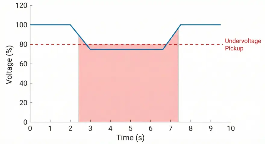
When the voltage drops below the pickup setting, the relay starts a timer. If the voltage remains below the threshold for a duration longer than the preset time delay, the relay sends a trip signal to the associated circuit breaker. The circuit breaker then opens and disconnects the affected load or section from the power supply.
The time delay is an important feature. It prevents the relay from tripping during brief voltage dips that are transient in nature. Momentary voltage sags caused by motor starting or fault clearing on adjacent circuits should not cause unnecessary tripping. The time delay allows the system to ride through these short disturbances without interruption.
Here is a simple example: Suppose an undervoltage relay is set to pick up at 80% of the rated voltage with a 5-second time delay. If the bus voltage drops to 75% and stays at that level for more than 5 seconds, the relay will issue a trip command. If the voltage recovers to above 80% within 5 seconds, the relay resets and no tripping occurs.
4. ANSI Code 27: The Undervoltage Relay
As mentioned earlier, the ANSI/IEEE Standard C37.2 assigns Device Number 27 to the undervoltage relay. This standard provides a system of device function numbers used in electrical power system protection and control diagrams.
Here are some related ANSI device numbers that engineers often encounter alongside Device 27:
| ANSI Code | Device Function |
|---|---|
| 27 | Undervoltage Relay |
| 59 | Overvoltage Relay |
| 47 | Phase-Sequence or Phase-Balance Voltage Relay |
| 81 | Frequency Relay |
| 51 | AC Time Overcurrent Relay |
| 50 | Instantaneous Overcurrent Relay |
In many industrial and utility applications, Device 27 is used in combination with other protection functions within a multifunction relay. Modern microprocessor-based relays can incorporate Device 27, Device 59, Device 81, and many other functions in a single hardware unit.
5. Types of Undervoltage Protection
Undervoltage protection can be categorized based on the application, the type of relay used, and the system configuration.
5.1 Single-Phase Undervoltage Protection
This type monitors only one phase voltage. It is used in single-phase systems or where monitoring one phase is sufficient to represent the overall voltage condition. Residential and small commercial applications often use single-phase undervoltage devices.
5.2 Three-Phase Undervoltage Protection
In three-phase industrial systems, it is necessary to monitor all three phase voltages. A three-phase undervoltage relay checks each phase individually and can trip if any one phase drops below the set threshold. This approach provides more complete protection compared to single-phase monitoring.
5.3 Positive-Sequence Undervoltage Protection
Some advanced relays calculate the positive-sequence voltage from the three-phase voltage inputs. The positive-sequence voltage gives a more accurate representation of the overall system voltage condition. It filters out the effects of unbalanced voltages and provides a cleaner measurement for protection decisions.
5.4 Instantaneous Undervoltage Protection
In certain applications, a time delay is not acceptable. The relay must act immediately when the voltage drops below the threshold. This type is used where even a brief period of low voltage can cause damage or safety hazards.
5.5 Time-Delayed Undervoltage Protection
This is the most common type. A definite time delay is added to prevent unnecessary tripping during transient conditions. The time delay is adjustable and is coordinated with other protection devices in the system.
6. Applications of Undervoltage Protection
Undervoltage protection is applied across a wide range of electrical systems. Let us look at the most common applications in detail.
6.1 Motor Protection
Electric motors are the primary beneficiaries of undervoltage protection. When the supply voltage to an induction motor drops, the motor draws more current to deliver the same mechanical power. This increased current overheats the motor windings. Prolonged operation under low voltage conditions causes insulation breakdown and eventual motor failure.
An undervoltage relay at the motor control center (MCC) trips the motor contactor or circuit breaker when the voltage drops below a safe level. This protects the motor from thermal damage effectively.
Example: A 200 kW induction motor is rated for 400V. The undervoltage relay is set at 85% of rated voltage, which is 340V. If the supply voltage falls to 330V and remains there for the preset time delay, the relay trips the motor breaker.
6.2 Generator Protection
Generators require undervoltage protection for several reasons. A drop in generator terminal voltage may indicate a problem with the excitation system. It could also indicate an overloaded condition. The undervoltage relay (Device 27) on a generator detects these conditions and can initiate alarms or trip the generator breaker.
6.3 Bus Protection
In substations and industrial plants, buses distribute power to multiple feeders and loads. An undervoltage condition on a bus affects all connected loads. Undervoltage relays are installed on buses to detect low voltage and initiate load shedding or bus transfer schemes automatically.
6.4 Automatic Transfer Switches (ATS)
Automatic transfer switches use undervoltage detection to determine when the main power source has failed. When the voltage on the primary source drops below the undervoltage threshold, the ATS switches the load to a standby source, such as an emergency generator. This application is found in hospitals, data centers, and other facilities where continuous power supply is mandatory.
6.5 Load Shedding
During system disturbances, the voltage may drop across the entire network. Undervoltage relays can be used to implement automatic load shedding. Non-priority loads are tripped first to reduce the overall demand. This helps the system voltage recover and prevents a cascading failure.
6.6 Transmission and Distribution Systems
Utilities use undervoltage protection on transmission lines and distribution feeders to detect abnormal voltage conditions. These relays work alongside other protection schemes to maintain voltage stability across the grid.
7. Undervoltage Protection Settings
Proper relay settings are necessary for effective undervoltage protection. Incorrect settings can lead to either nuisance tripping or failure to protect. Let us discuss the important settings.
7.1 Pickup Voltage
The pickup voltage is the voltage threshold below which the relay activates. It is expressed as a percentage of the nominal or rated voltage. Common pickup settings range from 70% to 90% of rated voltage, depending on the application.
- Motor protection: 80% to 85% of rated voltage
- Bus protection: 80% to 90% of rated voltage
- Generator protection: 85% to 90% of rated voltage
- ATS applications: 70% to 85% of rated voltage
7.2 Time Delay
The time delay setting determines how long the voltage must remain below the pickup level before the relay trips. This delay prevents nuisance tripping during short-duration voltage sags.
- Motor applications: 1 to 5 seconds
- Bus protection: 2 to 10 seconds
- ATS applications: 0.5 to 3 seconds
- Load shedding: 1 to 10 seconds (staged)
7.3 Dropout (Reset) Voltage
The dropout or reset voltage is the level at which the relay resets after the voltage recovers. The dropout voltage is set slightly higher than the pickup voltage to provide a hysteresis band. This hysteresis prevents the relay from chattering when the voltage oscillates near the pickup value.
Example: If the pickup is set at 80%, the dropout might be set at 85%. This means the relay picks up when voltage drops below 80% and resets only when the voltage recovers above 85%.
8. Undervoltage Relay Technologies
The technology used in undervoltage relays has evolved over the decades. Let us review the main types.
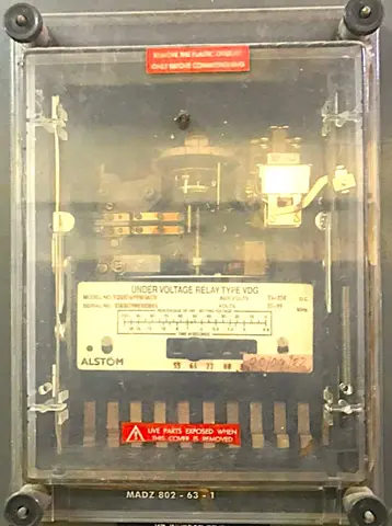
8.1 Electromechanical Relays
These are the oldest type of undervoltage relays. They use an electromagnetic coil that is energized by the system voltage. When the voltage drops, the magnetic force decreases and a spring mechanism releases the relay contacts. Electromechanical undervoltage relays are simple and robust but offer limited adjustability and no communication capabilities.
8.2 Static (Solid-State) Relays
Static relays replaced electromechanical relays in many applications during the 1970s and 1980s. They use analog electronic circuits to measure voltage and compare it against a reference. Static relays offer better accuracy, faster response, and more flexibility in settings compared to electromechanical types.
8.3 Microprocessor-Based (Numerical/Digital) Relays
Modern undervoltage relays are microprocessor-based. They offer high accuracy, multiple protection functions in a single unit, programmable settings, event recording, and communication capabilities. These relays can be integrated into SCADA systems and allow remote monitoring and configuration.
Most modern motor protection relays, generator protection relays, and feeder protection relays include Device 27 as one of many built-in protection functions.
9. Undervoltage Protection in Motor Control Centers (MCCs)
Motor control centers are a common location for undervoltage protection in industrial plants. The undervoltage relay monitors the bus voltage feeding the MCC. If the voltage drops below the set threshold, the relay can perform one or more of the following actions:
- Trip individual motor starters: Prevent motors from operating under low voltage conditions.
- Trip the main breaker of the MCC: Disconnect the entire MCC from the supply.
- Initiate sequential restart: After the voltage recovers, motors are restarted in a planned sequence to avoid a large inrush current that could cause the voltage to drop again.
Sequential restart is important because simultaneously restarting all motors after a voltage recovery would draw enormous inrush current. This inrush could pull the voltage back down and trigger the undervoltage relay again. A well-designed sequential restart program staggers the motor starts over a period of time.
10. Undervoltage Protection Coordination
Coordination of undervoltage protection with other protective devices is necessary to avoid nuisance tripping and to maintain system stability.
10.1 Coordination with Overcurrent Protection
Undervoltage relays and overcurrent relays must be coordinated so that fault currents are cleared by the overcurrent protection before the undervoltage relay trips healthy loads. The undervoltage relay time delay should be set longer than the fault clearing time of the overcurrent relays on the faulted circuit.
Example: If a fault on a feeder is cleared by the overcurrent relay in 0.5 seconds, the undervoltage relay on the bus should have a time delay of at least 1 to 2 seconds. This way, the fault is cleared first, the voltage recovers, and the undervoltage relay does not trip the healthy loads.
10.2 Coordination with Motor Starting
Large motor starts cause temporary voltage dips. The undervoltage relay must be set to ride through these dips without tripping. The time delay should be longer than the duration of the voltage dip during the largest motor start on the bus.
10.3 Coordination with Automatic Transfer Schemes
When undervoltage relays are used in automatic bus transfer schemes, they must coordinate with the transfer switch timing. The undervoltage detection must be fast enough to initiate the transfer but not so fast that it transfers during a normal transient.
11. Standards and Guidelines for Undervoltage Protection
Several industry standards provide guidance on undervoltage protection design, settings, and application.
- ANSI/IEEE C37.2: Standard for electrical power system device function numbers and contact designations. Defines Device 27 as the undervoltage relay.
- IEEE C37.96: Guide for AC motor protection. Provides recommendations for undervoltage protection settings for motors.
- IEEE C37.102: Guide for AC generator protection. Covers undervoltage protection of generators.
- IEC 60255: Defines requirements for measuring relays and protection equipment, including undervoltage relays.
- NEMA MG 1: Provides motor design standards, including voltage tolerance limits that inform undervoltage protection settings.
- NEC (NFPA 70): The National Electrical Code requires undervoltage protection for certain motor installations to prevent automatic restart after a power interruption.
According to NEMA MG 1, motors should be capable of operating at ±10% of rated voltage. This means a motor rated at 480V should operate between 432V and 528V. The undervoltage protection pickup should be set at or slightly below the lower limit of this range.
12. Undervoltage Protection vs. Overvoltage Protection
It is useful to compare undervoltage protection (Device 27) with overvoltage protection (Device 59) to clearly distinguish between the two.
| Parameter | Undervoltage (27) | Overvoltage (59) |
|---|---|---|
| Trigger Condition | Voltage drops below threshold | Voltage rises above threshold |
| Common Causes | Overloading, faults, loss of generation | Load rejection, capacitor switching, generator overspeed |
| Equipment Damage | Overcurrent, overheating | Insulation breakdown, flashover |
| Time Delay | Usually 1-10 seconds | Usually 0.5-5 seconds |
Both protection functions are often implemented in the same relay unit in modern installations.
13. Practical Example: Undervoltage Protection Scheme for an Industrial Plant
Let us walk through a practical example of designing an undervoltage protection scheme for a medium-sized industrial plant.
System Details:
- Main supply: 13.8 kV utility feed stepped down to 4.16 kV via a transformer
- A 4.16 kV bus feeds two large motors (500 kW each) and three distribution feeders
- A standby generator (2 MW at 4.16 kV) is available for emergency power
Protection Design:
- Device 27 on the 4.16 kV bus: Set at 85% of rated voltage (3.536 kV) with a 3-second time delay. If the bus voltage drops below 3.536 kV for more than 3 seconds, the relay initiates an alarm. If the voltage drops below 70% (2.912 kV) with a 1-second time delay, the relay trips the incoming breaker and initiates automatic transfer to the standby generator.
- Device 27 on each motor feeder: Set at 80% of rated voltage with a 2-second time delay. If the voltage drops below this level, the individual motor breaker trips. After voltage recovery, the motors are restarted sequentially with a 10-second interval between starts.
- Device 27 on the ATS: Set at 80% of rated voltage with a 2-second time delay. Upon detection, the ATS transfers the load to the standby generator.
This scheme protects the motors from damage, prevents cascading failures, and enables a smooth transition to backup power during voltage disturbances.
14. Testing Undervoltage Protection
Regular testing of undervoltage relays is necessary to confirm that they operate correctly when needed. Here is a summary of the standard tests performed.
14.1 Pickup Test
A variable voltage source is connected to the relay input. The voltage is gradually reduced from nominal until the relay picks up. The actual pickup voltage is compared with the set value. The relay should pick up within ±2% to ±5% of the setting, depending on the relay type and manufacturer specifications.
14.2 Time Delay Test
The voltage is suddenly reduced to a level below the pickup setting. The time between the voltage drop and the relay output contact operation is measured. This time should match the set time delay within the manufacturer’s stated tolerance.
14.3 Dropout (Reset) Test
After the relay has picked up, the voltage is slowly increased until the relay resets. The reset voltage is recorded and compared against the expected dropout setting.
14.4 Functional Trip Test
The relay output is connected to the circuit breaker trip circuit. A simulated undervoltage condition is applied to verify that the relay successfully trips the breaker. This end-to-end test confirms the integrity of the entire protection chain from the relay input to the breaker operation.
15. Conclusion
Undervoltage protection, designated as ANSI Device 27, is a fundamental protection function in electrical power systems. It monitors the voltage and acts to disconnect loads or initiate transfer schemes when the voltage drops below a safe operating level. Motors, generators, buses, and transfer switches all benefit from properly designed undervoltage protection.
The key to effective undervoltage protection lies in correct pickup and time delay settings, proper coordination with other protective devices, and regular testing. Engineers must consider the specific characteristics of their power system and the equipment being protected when designing these schemes.
16. Frequently Asked Questions (FAQs)
The ANSI code for undervoltage protection is Device 27, as defined by ANSI/IEEE Standard C37.2. This number is used in protection and control diagrams to identify the undervoltage relay.
Undervoltage protection (Device 27) acts when the voltage drops below a preset level. Overvoltage protection (Device 59) acts when the voltage rises above a preset level. Both protect equipment from operating outside the acceptable voltage range.
Common causes include heavy loading, power system faults, loss of generation, long distribution feeders, and large motor starting. Each of these conditions can reduce the voltage below acceptable levels.
A time delay prevents the relay from tripping during brief and harmless voltage dips. Transient voltage sags from motor starting or fault clearing on adjacent circuits should not cause unnecessary disconnection of healthy loads.
The pickup is usually set between 80% and 85% of rated voltage for motor protection. The exact setting depends on the motor’s voltage tolerance and the characteristics of the power supply system.
Yes. When voltage drops, a motor draws more current to maintain its output. This excess current causes overheating of the windings. Prolonged operation under low voltage can destroy the motor insulation and lead to motor failure.
A common practice is to test undervoltage relays every 1 to 3 years. Facilities with high reliability requirements may test more frequently.
The NEC (NFPA 70) requires undervoltage protection for certain motor installations to prevent automatic restart after a power interruption. Article 430 of the NEC addresses motor control and protection requirements, including undervoltage provisions.
An undervoltage relay is a separate protective device that monitors voltage and sends a trip signal. An undervoltage release is a mechanical device built into a circuit breaker that causes the breaker to trip when the coil voltage drops. Both serve the same purpose but differ in their construction and application.