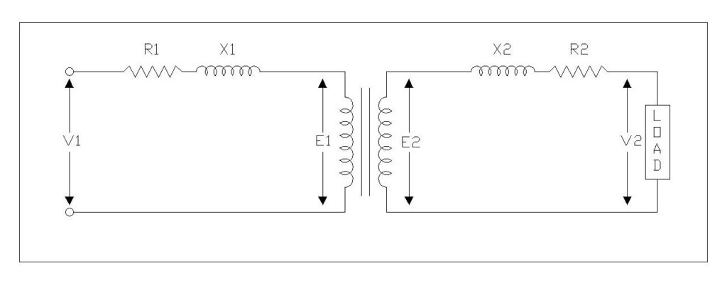
Every transformer experiences a change in its secondary terminal voltage as load increases from zero to its rated value. This change, expressed as a percentage, is called voltage regulation. It tells us how well a transformer maintains a steady output voltage under varying load conditions.
Voltage regulation matters because electrical equipment connected to the transformer secondary side needs a stable voltage supply to operate correctly. Motors, lighting systems, electronic devices, and industrial machinery can all suffer from poor performance, overheating, or even permanent damage if the supply voltage fluctuates beyond acceptable limits. Standards such as IEEE C57.12.00 and IEC 60076 set specific requirements for transformer voltage regulation to protect both equipment and end users.
In this technical guide, we will discuss everything you need to know about transformer voltage regulation, including its definition, mathematical formulas, phasor diagram analysis, power factor effects, zero and maximum regulation conditions, influencing factors, improvement methods, and practical calculation examples. Real-world scenarios are included throughout to help you apply these concepts confidently.
1. What is Voltage Regulation of a Transformer?
Voltage regulation of a transformer is the percentage change in secondary terminal voltage from no-load to full-load, with the primary voltage held constant.
Here is what happens in simple terms. A transformer running without any load connected to its secondary has almost no current flowing through its windings. The voltage drops across the winding resistance and leakage reactance are negligible at this point. The secondary terminal voltage is at its highest value under this condition.
As you connect a load and increase it toward the transformer’s rated capacity, current begins flowing through both primary and secondary windings. This current produces voltage drops across the internal resistance and leakage reactance of the windings. These drops cause the secondary terminal voltage to fall below its no-load value. The difference between the no-load and full-load secondary voltage, expressed as a percentage of the no-load voltage, gives us the voltage regulation.
A lower voltage regulation percentage indicates a better-performing transformer. It means the output voltage stays relatively stable even as load varies. An ideal transformer would have zero voltage regulation, but that is impossible in practice because every real transformer has some internal impedance.
2. Why Voltage Regulation Matters
Voltage regulation has a direct impact on the quality of power delivered to electrical loads. Sensitive electronic equipment, medical instruments, and precision manufacturing machinery all require voltage within a narrow band to function properly. A transformer with poor voltage regulation causes the output voltage to sag under load, leading to equipment malfunction, reduced efficiency, and accelerated wear.
Voltage regulation also serves as a measure of transformer design quality. A transformer with low regulation values has been designed with minimal internal impedance, good magnetic coupling between windings, and appropriate conductor sizing. These are all indicators of a well-engineered product.
From a compliance standpoint, national and international standards mandate specific voltage regulation limits. IEEE C57.12.00 (IEEE Standard General Requirements for Liquid-Immersed Distribution, Power, and Regulating Transformers) and IEC 60076 (Power Transformers) both address voltage regulation requirements. Transformers installed in utility and industrial applications must meet these standards to receive certification and approval for service.
Voltage regulation values for different transformer types are:
- Distribution transformers: 2% to 5%
- Power transformers: 2% to 4%
- Instrument transformers: Less than 1%
3. Voltage Regulation Formula
The standard formula for transformer voltage regulation is:
\( \text{Voltage Regulation (%)} = \frac{E_2 – V_2}{E_2} \times 100 \)
where:
- \(E_2\) = Secondary terminal voltage at no-load
- \(V_2\) = Secondary terminal voltage at full-load
This formula tells us how much the secondary voltage drops as a percentage of the no-load voltage. A transformer with a regulation of 4% means the output voltage falls by 4% of its no-load value at full load.
The ideal case would be \(E_2=V_2\), giving zero voltage regulation. In practice, however, every transformer has winding resistance and leakage reactance that produce voltage drops under load. The goal of good transformer design is to keep this regulation value as small as practically achievable.
3.1 Numerical Example
A single-phase transformer has a no-load secondary voltage of 240 V and a full-load secondary voltage of 230 V. The voltage regulation is:
\(\text{VR(%)}= \frac{240-230}{240}\times 100 = 4.17\%\)
This means the secondary voltage drops by approximately 10 volts (4.17% of 240 V) from no-load to full-load operation.
4. Approximate and Exact Voltage Regulation Formulas
4.1 Approximate Formula
The approximate voltage regulation formula accounts for load power factor and is widely used for quick calculations:
\(\text{VR (%)} = R_{pu}cos \phi \pm X_{pu}sin \phi\)
where,
- \(R_{pu}\) = Per-unit (or percentage) resistance of the transformer
- \(X_{pu}\) = Per-unit (or percentage) reactance of the transformer
- \(\phi\) = Power factor angle of the load
The positive sign (+) applies for lagging (inductive) power factor loads.
The negative sign (−) applies for leading (capacitive) power factor loads.
This can also be written using actual secondary quantities as:
\(\text{VR} = \frac{I_2R_{02} cos\phi \pm I_2X_{02} sin\phi}{E_2}\)
where \(I_2\) is the secondary load current, \(R_{02}\) is the total equivalent resistance referred to secondary, and \(X_{02}\) is the total equivalent reactance referred to secondary.
4.2 Exact Formula
The approximate formula works well for most distribution and power transformers with low impedance values. However, for transformers with higher impedance or when greater accuracy is needed, the exact formula should be used:
\(E_2= \sqrt{(V_2 cos\phi + I_2 R_{02})^2 + (V_2 sin\phi \pm I_2 X_{02})^2}\)
Then:
\(\text{VR (%)} = \frac{E_2 – V_2}{E_2} \times 100\)
The approximate formula ignores the second-order terms that arise from the geometry of the phasor diagram, while the exact formula accounts for them. For transformers with impedance below 5%, the difference between the two formulas is usually less than 0.1%, making the approximate formula adequate for most practical applications.
5. Phasor Diagram for Voltage Regulation
The phasor diagram provides a visual representation of how voltage drops across transformer impedance affect the secondary terminal voltage. It makes the relationship between power factor and voltage regulation much easier to grasp.
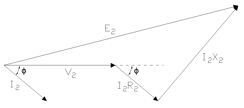
5.1 Phasor Diagram for Lagging Power Factor
For a lagging power factor load, the load current \(I_2\) lags behind the secondary terminal voltage \(V_2\) by an angle \(\phi\). Starting from the \(V_2\) phasor:
- Add the resistive voltage drop \(I_2 R_{02}\) in phase with the current \(I_2\)
- Add the reactive voltage drop \(I_2 X_{02}\) perpendicular to the current \(I_2\) (leading \(I_2\) by 90°)
- The resultant phasor gives \(E_2\), the no-load voltage
The length of \(E_2\) is clearly greater than \(V_2\) in this case, resulting in positive voltage regulation. The larger the angle \(\phi\) and the larger the impedance drops, the greater the difference between \(E_2\) and \(V_2\).
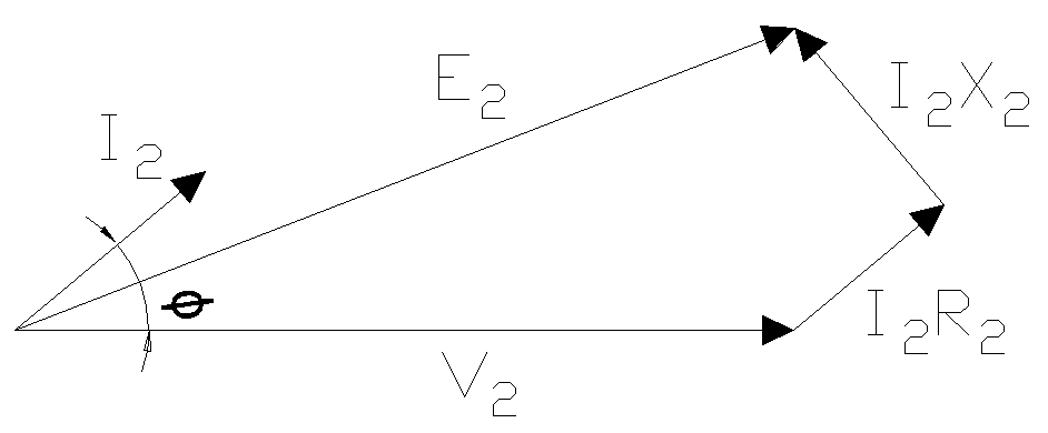
5.2 Phasor Diagram for Leading Power Factor
For a leading power factor load, \(I_2\) leads \(V_2\) by angle \(\phi\). The reactive voltage drop \(I_2 X_02\) now points in a direction that partially cancels the resistive drop. Depending on the magnitude of the leading power factor, \(E_2\) can end up being shorter than \(V_2\), resulting in negative voltage regulation.
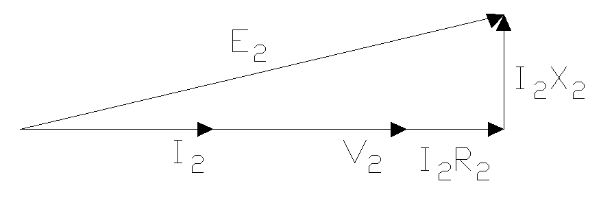
5.3 Phasor Diagram for Unity Power Factor
At unity power factor, \(I_2\) is in phase with \(V_2\). The resistive drop \(I_2 R_02\) adds directly in phase with \(V_2\), while the reactive drop \(I_2 X_{02}\) is perpendicular. The regulation is moderate and positive, determined primarily by the resistive component.
6. Effect of Power Factor on Voltage Regulation
The power factor of the connected load has a major influence on transformer voltage regulation. The same transformer can show very different regulation values depending on whether the load is inductive, capacitive, or resistive. Let us examine each case.
6.1 Lagging Power Factor (Inductive Loads)
When a transformer supplies inductive loads such as motors, induction furnaces, or fluorescent lighting ballasts, the load current lags behind the voltage by an angle \(\phi\). For lagging power factor conditions, the voltage regulation formula becomes:
\(\text{VR} = R \cos\phi + X \sin\phi \)
Both the resistive and reactive voltage drops add together, producing a high positive regulation value. The secondary voltage drops as load increases. This is the most common scenario in industrial power systems, where motor loads dominate.
Example: A transformer has \(R_{pu}=2\%\) and \(X_{pu}=5\%\), supplying a load at 0.8 lagging power factor \((cos\phi=0.8, sin\phi=0.6)\):
\(\text{VR}=2\times 0.8 + 5\times 0.6 = 1.6 + 3.0 = 4.6\%\)
6.2 Leading Power Factor (Capacitive Loads)
Capacitive loads, including synchronous condensers, power factor correction capacitors, and certain electronic power supplies, cause the load current to lead the voltage. For leading power factor conditions, the voltage regulation expression becomes:
\( \text{VR} = R \cos\phi – X \sin\phi \)
The reactive drop opposes the resistive drop here. If the reactive component is large enough, the total regulation becomes negative. A negative voltage regulation means the full-load secondary voltage is actually higher than the no-load voltage.
Negative voltage regulation is not always desirable. A sustained overvoltage at the secondary terminals can damage insulation, cause overexcitation of connected equipment, and push the transformer core toward saturation. Engineers must account for this possibility when designing systems with large capacitor banks or lightly loaded cables that exhibit capacitive behavior.
Example: Same transformer (\(R_{pu}=2\%,\, X_{pu}=5\%)\) at 0.8 leading power factor:
\(VR=2\times 0.8 − 5 \times 0.6 = 1.6 − 3.0 = −1.4\%\)
The negative value tells us the full-load voltage exceeds the no-load voltage by 1.4%.
6.3 Unity Power Factor (Resistive Loads)
For purely resistive loads such as incandescent lighting and heating elements, the power factor equals unity (\(cos\phi=1\), \(\sin\phi=0\)). The voltage regulation simplifies to:
\(\text{VR} = R \cos\phi = R \)
Only the resistive drop contributes to voltage regulation. This gives a moderate regulation value, lower than lagging power factor but higher than leading power factor for the same transformer.
Example: Same transformer at unity power factor:
\(\text{VR}=2\times 1 + 5 \times 0=2\%\)
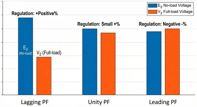
6.4 Summary Table
| Load Power Factor | Sign in Formula | Regulation Magnitude | Secondary Voltage Behavior |
|---|---|---|---|
| Lagging (inductive) | Positive (+) | High positive | Drops under load |
| Unity (resistive) | R term only | Moderate positive | Moderate drop under load |
| Leading (capacitive) | Negative (−) | Low positive or negative | May rise under load |
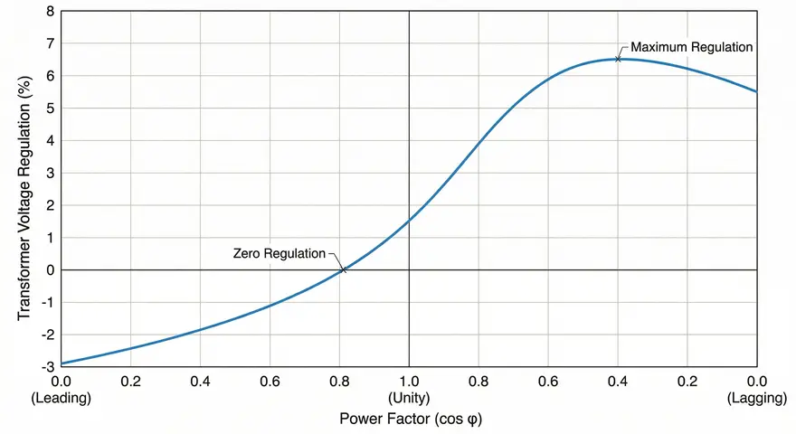
7. Condition for Zero Voltage Regulation
Zero voltage regulation is the condition where the full-load and no-load secondary voltages are exactly equal. This can happen at a specific leading power factor where the resistive voltage drop and reactive voltage drop cancel each other out.
For zero regulation, we set:
\( R \cos\phi = X \sin\phi \)
Dividing both sides:
\( \tan\phi = \frac{R}{X} \)
The power factor angle at which zero regulation occurs is:
\( \phi = \arctan\left(\frac{R}{X}\right) \)
And the corresponding power factor is:
\( \cos\phi = \frac{X}{\sqrt{R^2 + X^2}} = \frac{X}{Z} \)
This power factor must be leading (capacitive load) because zero regulation requires the reactive drop to offset the resistive drop. Looking back at the voltage regulation formula, only the leading power factor case (with the negative sign before the \(X sin\phi\) term) allows this cancellation to occur.
At power factors more leading than this value, regulation becomes negative, meaning the full-load voltage exceeds the no-load voltage.
7.1 Example
A transformer with \(R_{pu}=2\%\) and \(X_{pu}=5\%\):
\(tan\phi=\frac{2}{5}=0.4\)
\(\phi = \arctan(0.4) = 21.8^{\circ}\)
\( cos\phi=cos(21.8^{\circ})=0.929 \text{(leading)}\)
Zero voltage regulation occurs at 0.929 leading power factor for this transformer.
8. Condition for Maximum Voltage Regulation
Maximum voltage regulation does not occur at zero power factor lagging, as is sometimes incorrectly stated. It occurs at a specific lagging power factor angle that can be found by differentiating the voltage regulation expression and setting it to zero.
Starting with the lagging power factor formula:
\(\text{VR}= R cos \phi + X sin\phi\)
Taking the derivative with respect to \(\phi\) and setting it to zero:
\(\frac{d\text{(VR)}}{d\phi} = – R sin \phi + X cos \phi = 0\)
Solving:
\(tan\phi = \frac{X}{R}\)
\(\phi = arctan \frac{X}{R}\)
At this angle, the maximum voltage regulation is:
\(\text{VR}_{max}= \sqrt{R^2 + X^2} = Z_{pu}\)
This result makes intuitive sense from the phasor diagram. Maximum regulation occurs when the load current is aligned in the direction that produces the largest possible difference between \(E_2\) and \(V_2\).
8.1 Example
For a transformer with \(R_{pu}=2\%\) and \(X_{pu}=5\%\):
\(tan\phi=\frac{5}{2}=2.5\)
\(\phi=arctan(2.5)=68.2^{\circ}\)
\(cos\phi=cos(68.2^{\circ})=0.371 \text{(lagging)}\)
\(\text{VR}_{max}=\sqrt{2^2+5^2}=\sqrt{29}=5.39\%\)
Maximum voltage regulation of 5.39% occurs at 0.371 lagging power factor.
9. Practical Calculation Examples
To illustrate the practical application of voltage regulation concepts, consider some examples encountered in electrical engineering practice.
9.1 Example 1: Basic Voltage Regulation Calculation
A 10 kVA single-phase transformer has a no-load secondary voltage of 440 V. The secondary terminal voltage drops to 418 V at full load. Calculate the voltage regulation.
Solution:
\(\text{VR} (\%) = \frac{E_2 – V_2}{E_2}\times 100\)
\(\text{VR} (\%) = \frac{440 – 418}{440} \times 100 = \frac{22}{440}\times 100 =5.0\% \)
The secondary voltage drops by 22 V, which is 5.0% of the no-load voltage. This falls in the acceptable range but is on the higher side for a distribution transformer. Power quality at the load terminals may be a concern if the connected equipment is voltage-sensitive.
9.2 Example 2: Regulation at Different Power Factors
A 25 kVA, 6600/400 V single-phase transformer has an equivalent percentage resistance of 1.8% and an equivalent percentage reactance of 4.2%. Calculate the voltage regulation at full load for:
- (a) 0.85 lagging power factor
- (b) 0.85 leading power factor
- (c) Unity power factor
Solution:
(a) 0.85 lagging power factor:
Given, \(cos \phi =0.85\)
So, \(sin\phi=\sqrt{1-cos\phi^2}\)
\(sin\phi= \sqrt{1-0.85^2}=\sqrt{1-0.7225}=\sqrt{0.2775} = 0.527\)
\(\text{VR}=R cos\phi + X sin\phi\)
\(\text{VR}= 1.8 \times 0.85 +4.2\times 0.527\)
\(\text{VR}=1.53+2.213 = 3.74\%\)
The transformer shows 3.74% regulation at 0.85 lagging power factor. This is a good regulation value for an industrial distribution transformer serving motor loads.
(b) 0.85 leading power factor:
\(\text{VR}=R cos\phi – X sin\phi\)
\(\text{VR}= 1.8 \times 0.85 – 4.2\times 0.527\)
\(\text{VR}=1.53-2.213 = -0.683\%\)
The negative sign tells us the full-load secondary voltage is 0.683% higher than the no-load voltage. The capacitive load creates a voltage rise across the leakage reactance that exceeds the resistive drop.
(c) Unity power factor:
\(cos\phi=1, \, sin\phi=0\)
\(\text{VR}=R cos\phi + X sin\phi=1.8\times 1+ 4.2\times 0=1.8\%\)
At unity power factor, only the resistive component contributes. The 1.8% regulation is excellent and shows how much the reactive component affects regulation at non-unity power factors.
9.3 Example 3: Finding No-Load Voltage from Known Regulation
A transformer with 3.5% voltage regulation delivers 208 V at its secondary terminals under full-load conditions. Determine the no-load secondary voltage.
Solution:
Using the standard formula with \(E_2\) in the denominator:
\(\text{VR} = \frac{E_2 – V_2}{E_2}\)
\(0.035 = \frac{E_2 – 208}{E_2}\)
\(0.035\times E_2 = E_2-208\)
\(208=E_2-0.035\times E_2\)
\(208= E_2 (1-0.035) = 0.965\times E_2\)
\(E_2=\frac{208}{0.965}=215.54 V\)
The no-load secondary voltage is 215.54 V.
9.4 Example 4: Finding Maximum Voltage Regulation and Its Power Factor
A 100 kVA, 11 kV/433 V three-phase distribution transformer has an equivalent percentage resistance of 1.2% and an equivalent percentage reactance of 3.8%. Find the maximum voltage regulation and the power factor at which it occurs.
Solution:
Step 1: Find the power factor angle for maximum regulation.
\(tan\phi=\frac{X}{R}=\frac{3.8}{1.2}=3.167\)
\(\phi=\arctan (3.167) = 72.47^{\circ}\)
Step 2: Find the power factor.
\(cos\phi = cos (72.47^{\circ}) = 0.301\, \text{lagging}\)
Step 3: Calculate the maximum voltage regulation.
\(\text{VR}_{max}=\sqrt{R^2+X^2}=\sqrt{1.2^2+3.8^2}\)
\(\text{VR}_{max}==\sqrt{1.44+14.44}=\sqrt{15.88}=3.985\%\)
Maximum voltage regulation of 3.985% occurs at 0.301 lagging power factor for this transformer.
10. Factors Affecting Voltage Regulation
10.1 Transformer Internal Impedance
The winding resistance and leakage reactance of a transformer are the primary factors controlling voltage regulation. Higher impedance produces greater voltage drops under load, resulting in poorer regulation.
Winding resistance depends on the conductor material (copper or aluminum), cross-sectional area of the conductors, total winding length, and operating temperature. Copper windings offer lower resistance compared to aluminum for the same conductor size, which is why copper-wound transformers generally exhibit better voltage regulation.
Leakage reactance arises from magnetic flux that links only one winding without coupling to the other. It depends on winding geometry, the physical spacing between primary and secondary windings, and the core configuration. Interleaved or sandwich-type winding arrangements reduce leakage reactance by improving the magnetic coupling between windings.
10.2 Load Magnitude
As load current increases from zero toward the rated value, voltage drops across the internal impedance grow proportionally. A transformer operating at 50% load will show roughly half the voltage regulation it exhibits at full load. Heavy overloading pushes voltage regulation beyond rated values and can cause unacceptable voltage drops at the secondary terminals.
10.3 Load Power Factor and Harmonics
As discussed in detail earlier, lagging power factor loads produce the worst voltage regulation while leading power factor loads can actually cause voltage rise at the secondary. Non-linear loads that generate harmonic currents create additional voltage distortion beyond what the fundamental frequency analysis predicts. Variable frequency drives, rectifiers, and switching power supplies are common sources of harmonic currents that worsen voltage regulation performance.
10.4 Transformer Design and Construction
The choice of core material affects magnetic properties and leakage characteristics. Modern grain-oriented electrical steel reduces core losses and improves magnetic coupling. Amorphous metal cores offer even better performance, though at higher manufacturing cost.
Winding configuration plays a major role too. Concentric windings (one inside the other) are standard in most transformers, but the spacing between windings directly affects leakage reactance. Disc-type windings can be arranged to minimize leakage flux paths. The number and placement of cooling ducts within the winding assembly also influence leakage reactance.
10.5 Operating Temperature
Temperature has a direct effect on winding resistance. Copper has a positive temperature coefficient of resistance — approximately 0.393% per degree Celsius at 20°C. A transformer running at 75°C above ambient will have winding resistance roughly 30% higher than at room temperature. This increased resistance produces larger voltage drops and worse voltage regulation.
11. Methods to Improve Voltage Regulation
Several practical techniques exist for improving voltage regulation in transformers and power distribution systems, each suited to specific applications and operating conditions.
11.1 Tap Changing Mechanisms
Tap changers adjust the transformer turns ratio by connecting to different tap points on a winding. This compensates for voltage variations caused by load changes or supply voltage fluctuations.
Off-load tap changers (OLTC) require the transformer to be de-energized before changing tap positions. They suit applications where voltage adjustments are infrequent, such as distribution transformers serving stable residential loads. These are simpler, less expensive, and require minimal maintenance.
On-load tap changers (LTC) allow tap changes while the transformer remains energized and serving load. They are standard equipment in substation power transformers and large distribution transformers. Modern on-load tap changers use vacuum interrupters or thyristor-based switching to minimize arcing during tap transitions. Per ANSI C84.1 (Electric Power Systems and Equipment — Voltage Ratings), the service voltage at utilization equipment should remain within ±5% of nominal, and on-load tap changers help maintain this requirement.
11.2 Reactive Power Compensation
Shunt capacitor banks installed at the load end supply reactive power locally. This reduces the reactive current component flowing through the transformer, which in turn reduces the reactive voltage drop \((IX)\) and improves voltage regulation. Shunt capacitors also improve the system power factor.
Series capacitors compensate directly for the inductive reactance of transformers and transmission lines. A series capacitor effectively cancels a portion of the line or transformer reactance, reducing the total impedance and improving voltage regulation. This technique is used mainly in long high-voltage transmission lines.
11.3 Voltage Regulators
Automatic voltage regulators (AVRs) continuously monitor the output voltage and make real-time adjustments to maintain it within specified limits. They respond faster than mechanical tap changers and provide more precise voltage control.
Static VAR compensators (SVCs) use thyristor-controlled reactors and thyristor-switched capacitors to inject or absorb reactive power dynamically. STATCOMs (Static Synchronous Compensators), a newer FACTS (Flexible AC Transmission Systems) device, offer even faster response and smoother voltage control using voltage-source converter technology.
11.4 System Design Optimization
Proper transformer sizing prevents overloading that worsens voltage regulation. A transformer continuously operated above 80% of its rated capacity will show higher regulation values. Selecting a transformer with adequate margin say 20% to 30% above the expected maximum load helps maintain good regulation throughout the operating range.
Using larger conductor sizes in distribution feeders reduces the total system impedance between the transformer and the load. Shorter feeder runs also help. Load balancing across phases in three-phase systems prevents excessive voltage drop on any single phase.
12. Relationship Between Voltage Regulation and Efficiency
Voltage regulation and transformer efficiency are related but distinct performance parameters. Both are affected by the transformer’s internal impedance, but they respond to different aspects of it.
Copper losses in a transformer equal \(I^2R\), where \(R\) is the total winding resistance. The same resistance that causes the resistive voltage drop \((IR)\) contributing to voltage regulation also causes power dissipation as heat. A transformer with lower winding resistance will have both better voltage regulation and lower copper losses, improving efficiency.
However, the relationship is not straightforward for several reasons. Transformer efficiency depends on both copper losses (load-dependent) and core losses (constant regardless of load). Maximum efficiency occurs at a specific loading point where copper losses equal core losses. This optimal loading point is independent of voltage regulation.
There is also a practical tradeoff to consider. Lower transformer impedance improves voltage regulation but increases the available fault current on the secondary side. Higher fault currents require more robust (and expensive) protective equipment. Engineers must balance voltage regulation, efficiency, and fault current levels during transformer selection.
13. Voltage Regulation Calculator
This interactive calculator simplifies voltage regulation analysis. It offers two calculation methods. The voltage-based method works when you have actual measurements of no-load and full-load secondary voltages. The parameter-based method lets you explore how transformer resistance, reactance, and load power factor affect regulation.
The calculator computes the regulation percentage and provides a color-coded interpretation: excellent (0–2%), good (2–4%), acceptable (4–6%), and poor (above 6%). The mathematical formula used for each calculation is displayed alongside the result.
⚡ Transformer Voltage Regulation Calculator
Calculate transformer voltage regulation using voltages or parameters. Results explain performance instantly!
Using No-load & Full-load Voltages
14. Conclusion
Voltage regulation is a fundamental performance parameter that defines how well a transformer maintains stable output voltage under changing load conditions. A strong grasp of voltage regulation formulas, phasor diagram analysis, and power factor effects allows electrical engineers to make informed decisions about transformer selection, system design, and voltage control strategies.
15. Frequently Asked Questions (FAQs)
A voltage regulation of 2% or less is considered excellent. Values between 2% and 4% are good for most applications. Regulation above 6% is generally considered poor and may cause problems for sensitive loads.
Yes. Negative voltage regulation occurs when the full-load secondary voltage exceeds the no-load voltage. This happens with capacitive (leading power factor) loads where the voltage rise across the transformer’s leakage reactance more than offsets the resistive voltage drop.
Voltage drop is the actual voltage difference (in volts) between no-load and full-load conditions. Voltage regulation is this drop expressed as a percentage of the no-load voltage.
Lagging (inductive) power factor increases voltage regulation because both resistive and reactive voltage drops add together. Leading (capacitive) power factor decreases regulation because the reactive drop subtracts from the resistive drop. Unity power factor gives moderate regulation from the resistive component alone.
Voltage regulation is measured by recording the secondary open-circuit voltage (no-load) and then measuring the secondary terminal voltage at rated full load with rated primary voltage applied. The percentage difference gives the voltage regulation. An open-circuit test and short-circuit test together provide the parameters needed to calculate regulation without full-load testing.