Every electrical machine has defined voltage and frequency ratings. Operating a transformer or generator within these ratings keeps the magnetic flux in the core at a safe level. But what happens when the voltage increases beyond the rated value or the frequency drops below its nominal value? The ratio of voltage to frequency (V/Hz) rises, and the magnetic core experiences a condition called overexcitation. Overexcitation forces the core into saturation, producing excessive heat, increased losses, and eventual damage to the insulation and laminations.
In this technical guide, we will discuss everything you need to know about volts-per-hertz protection, including its working principle, types, applications, relay settings, coordination strategies, testing methods, and relevant industry standards. Practical examples are included throughout to help you apply these concepts in real-world scenarios confidently.
1. What is Volts-Per-Hertz Protection?
Volts-per-hertz protection monitors the ratio of the applied voltage to the system frequency. This ratio is directly proportional to the magnetic flux in the core of a transformer or generator. Under normal operating conditions, the flux remains within safe limits because both voltage and frequency are at or near their rated values. The protection function activates when the V/Hz ratio exceeds normal levels, indicating that the core flux has risen above the design limit.
The ANSI device code for volts-per-hertz protection is ANSI 24 (also written as IEEE device number 24). You will find this function in modern numerical relays used for generator protection and transformer protection.
A simple formula illustrates the concept:
\(\boxed{\text{Flux} \,\left(\Phi\right) \propto \dfrac{V}{f}}\)
Where \(V\) is the terminal voltage and \(f\) is the system frequency.
If the voltage increases while the frequency remains constant, flux rises. If the frequency decreases while the voltage remains constant, flux also rises. Either scenario can push the magnetic core into saturation.
2. Why is Volts-Per-Hertz Protection Needed?
Magnetic cores in transformers and generators are designed to operate at a specific flux density. The core steel is selected and laminated to handle the rated flux without excessive losses. Once the flux exceeds the rated value, the core enters saturation. In saturation, the magnetic material can no longer support the increasing flux efficiently, and the excess flux spills into non-laminated parts of the machine, such as the core bolts, clamping structures, and tank walls.
This spillover flux causes localized heating. The temperature in these parts can rise quickly and damage the insulation. In generators, the stator core end regions are especially vulnerable. In transformers, the tank walls and structural components can overheat within minutes during severe overexcitation.
Here is a practical example. A 500 MVA generator operates at 20 kV and 60 Hz. Its rated V/Hz ratio is 20,000/60 = 333.3 V/Hz. If the automatic voltage regulator (AVR) malfunctions during startup and pushes the terminal voltage to 22 kV while the frequency is only 57 Hz, the V/Hz ratio becomes 22,000/57 = 385.96 V/Hz. This is approximately 1.158 per unit (pu) of the rated ratio. Such a condition requires prompt detection and corrective action.
3. Causes of Overexcitation
Several operating conditions can lead to overexcitation in generators and transformers. Knowing these causes helps protection engineers design appropriate settings and coordination schemes.
3.1 Generator-Side Causes
- Loss of automatic voltage regulator (AVR) control: The AVR controls the field current of a synchronous generator. If it malfunctions and applies excessive field current, the terminal voltage rises beyond the rated value, increasing the V/Hz ratio.
- Sudden load rejection: A large load rejection can cause the generator speed to increase rapidly. Although frequency rises, the voltage can increase even faster due to the sudden loss of reactive power demand, temporarily increasing the V/Hz ratio before governors and regulators respond.
- Manual operation of the voltage regulator: During commissioning or testing, operators sometimes run the excitation system in manual mode. In manual mode, the AVR does not automatically limit the field current, creating a risk of overexcitation.
- Startup and shutdown conditions: During these periods, the generator frequency is below nominal. If the excitation is applied before the generator reaches rated speed, the V/Hz ratio can be high even at reduced voltages.
3.2 Transformer-Side Causes
- Overvoltage on the power system: Transmission system voltage can rise during light load conditions, capacitor bank switching, or Ferranti effect on long transmission lines. This elevated voltage increases the V/Hz ratio on connected transformers.
- Frequency decay during system disturbances: During system islanding or generation-load imbalance events, the frequency can decline. If the voltage does not decrease proportionally, the transformer experiences overexcitation.
- Geomagnetic disturbances: Geomagnetically induced currents (GIC) can bias the transformer core flux, effectively pushing it toward saturation even at normal V/Hz ratios. Although this is a different mechanism, it produces similar thermal effects.
4. How Volts-Per-Hertz Protection Works
The ANSI 24 relay measures two quantities: the terminal voltage and the system frequency. It then calculates the V/Hz ratio and compares it to a set of predefined thresholds. The result is expressed in per unit (pu) of the rated V/Hz value.
For a generator rated at 13.8 kV and 60 Hz, the rated V/Hz is 13,800/60 = 230 V/Hz. If the relay measures 14.5 kV at 59 Hz, the V/Hz ratio is 14,500/59 = 245.76 V/Hz, which is 245.76/230 = 1.0685 pu.
The relay compares this measured value against its pickup settings. There are generally two types of operating characteristics:
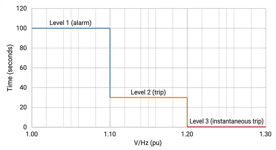
4.1 Definite Time Characteristic
The relay has one or more V/Hz pickup levels, each with a fixed time delay. If the V/Hz ratio exceeds a particular level and remains above it for the set time, the relay operates.
For example:
- Level 1 (Alarm): Pickup = 1.05 pu, Time Delay = 60 seconds
- Level 2 (Trip): Pickup = 1.10 pu, Time Delay = 10 seconds
- Level 3 (Instantaneous Trip): Pickup = 1.20 pu, Time Delay = 0 seconds
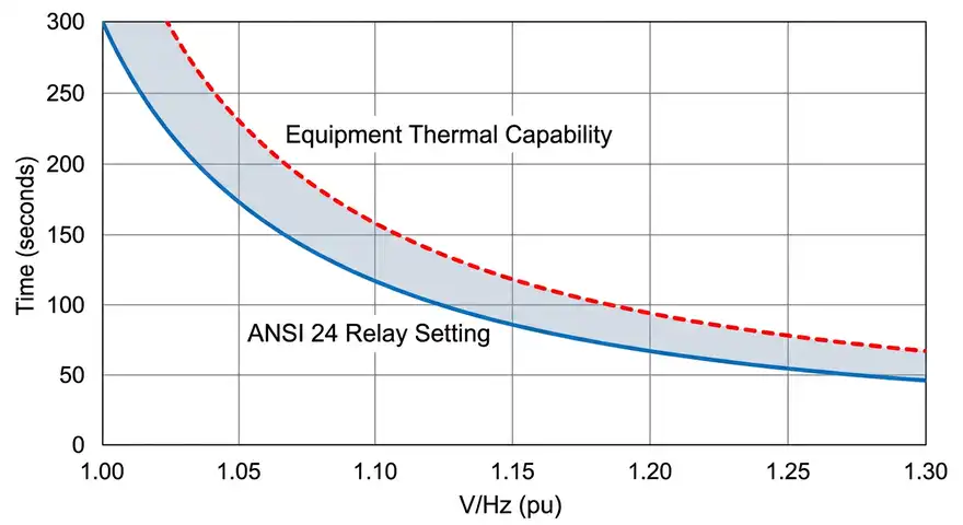
4.2 Inverse Time Characteristic
The relay operates on an inverse time curve where the operating time decreases as the V/Hz ratio increases. This characteristic closely matches the thermal capability of the protected equipment. At mild overexcitation levels, the equipment can tolerate the condition for a longer time. At severe overexcitation levels, damage occurs quickly, so the relay must trip faster.
Many modern numerical protection relays offer both definite time and inverse time characteristics. The protection engineer selects the appropriate characteristic based on the equipment manufacturer’s thermal capability data.
5. Thermal Capability Curves and Relay Coordination
Transformer and generator manufacturers provide thermal capability curves for their equipment. These curves show the maximum allowable time that the equipment can withstand a given V/Hz level without sustaining damage. The ANSI 24 relay settings must be coordinated with these curves so that the relay operates before the equipment reaches its thermal limit.
5.1 Example: Generator Thermal Capability
A generator manufacturer provides the following overexcitation withstand data:
| V/Hz (pu) | Maximum Allowable Time |
|---|---|
| 1.05 | Continuous |
| 1.10 | 120 seconds |
| 1.15 | 60 seconds |
| 1.20 | 12 seconds |
| 1.25 | 6 seconds |
The ANSI 24 relay inverse time curve must be set below this capability curve at every point. A common practice is to apply a safety margin of 80% to 90% of the manufacturer’s withstand time. So if the equipment can tolerate 1.15 pu for 60 seconds, the relay should trip at 1.15 pu within 48 to 54 seconds.
5.2 Example: Transformer Thermal Capability
IEEE C57.12.00 provides general guidance for transformer overexcitation limits. A common guideline states that transformers should not operate above 1.05 pu V/Hz at rated load and 1.10 pu V/Hz at no load on a continuous basis. For short-duration overexcitation, the manufacturer’s specific data should be used.
6. ANSI 24 Relay Settings: Step-by-Step
Setting a volts-per-hertz relay requires the following information:
- Rated voltage of the equipment
- Rated frequency of the system
- Equipment thermal capability curve from the manufacturer
- PT (potential transformer) and CT (current transformer) ratios
- Desired alarm and trip levels
Step 1: Determine the Rated V/Hz
For a 345 kV / 60 Hz transformer:
Rated V/Hz = 345,000 / 60 = 5,750 V/Hz (primary)
On the relay side, with a PT ratio of 345,000/115 = 3,000:1:
Rated V/Hz (secondary) = 115 / 60 = 1.917 V/Hz
The relay works in per unit, so the rated V/Hz corresponds to 1.00 pu.
Step 2: Set the Alarm Level
A common alarm setting is 1.05 pu with a time delay of 30 to 60 seconds. This gives the operator time to take corrective action, such as reducing the generator field current or adjusting the voltage.
Step 3: Set the Trip Levels
The trip settings should coordinate with the equipment thermal capability curve. For a definite time scheme:
- Trip Level 1: 1.10 pu, 45 seconds
- Trip Level 2: 1.15 pu, 20 seconds
- Trip Level 3: 1.20 pu, 2 seconds (or instantaneous)
For an inverse time scheme, select the relay curve shape that best fits below the thermal capability curve across the entire range.
Step 4: Verify Coordination
Plot the relay characteristic curve alongside the equipment thermal capability curve. Confirm that the relay curve falls below the equipment curve at every V/Hz level with an adequate margin.
7. Applications of Volts-Per-Hertz Protection
7.1 Generator Protection
ANSI 24 protection is a standard element in generator protection relay panels. Generators are particularly susceptible to overexcitation during startup, shutdown, and islanding conditions. The protection function is usually implemented within the main generator protection relay along with other functions like differential protection (ANSI 87G), loss of excitation (ANSI 40), and reverse power (ANSI 32).
During a load rejection event, the governor may not reduce the fuel input quickly enough, and the AVR may temporarily increase excitation. The V/Hz ratio can spike for several seconds. The ANSI 24 element must be set to allow short-duration, minor overexcitation events that the machine can handle, but it must trip for sustained or severe overexcitation.
7.2 Transformer Protection
Large power transformers connected to generators (generator step-up transformers or GSU transformers) frequently experience overexcitation events because they are directly coupled to the generator. If the generator experiences overexcitation, the GSU transformer does too.
Transmission transformers can also experience overexcitation during system-wide voltage rise events or when the system frequency drops. The ANSI 24 relay is often included in the transformer protection relay package for these transformers.
7.3 Synchronous Condenser Protection
Synchronous condensers are used for reactive power compensation. They operate similarly to generators but without a prime mover. They use excitation control to absorb or supply reactive power. Overexcitation protection is necessary for these machines because they can experience voltage control problems similar to generators.
8. Practical Example: Setting ANSI 24 for a 200 MW Generator
Let us walk through a complete example.
Equipment Data:
- Generator rating: 200 MW, 235 MVA, 18 kV, 60 Hz
- Rated V/Hz: 18,000 / 60 = 300 V/Hz = 1.00 pu
- PT ratio: 18,000 / 120 = 150:1
Manufacturer’s Overexcitation Capability:
| V/Hz (pu) | Allowable Time (seconds) |
|---|---|
| 1.05 | Continuous |
| 1.08 | 300 |
| 1.10 | 120 |
| 1.15 | 40 |
| 1.18 | 15 |
| 1.20 | 7 |
| 1.25 | 3 |
Relay Settings (Definite Time):
| Setting Level | V/Hz Pickup (pu) | Time Delay (seconds) | Action |
|---|---|---|---|
| Level 1 | 1.06 | 60 | Alarm |
| Level 2 | 1.10 | 100 | Trip |
| Level 3 | 1.15 | 32 | Trip |
| Level 4 | 1.20 | 5 | Trip |
Each trip setting is below the manufacturer’s allowable time, providing a margin for relay measurement and breaker operating time. The alarm at 1.06 pu gives operators early warning before the trip levels are reached.
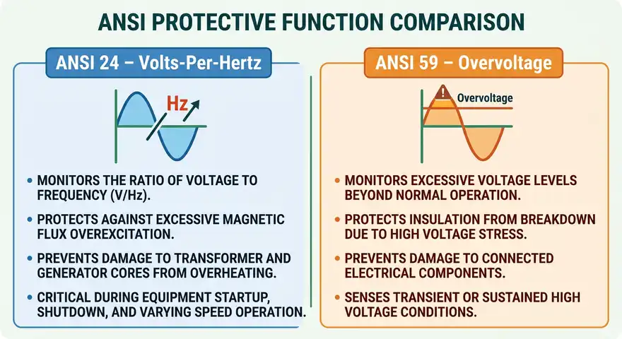
9. Differences Between ANSI 24 and ANSI 59 (Overvoltage Protection)
A common question among protection engineers is how ANSI 24 (volts-per-hertz) differs from ANSI 59 (overvoltage). Both functions monitor voltage, but they address different problems.
ANSI 59 (Overvoltage) monitors only the voltage magnitude. It does not consider the frequency. Its purpose is to protect equipment from voltage levels that exceed the insulation rating. The pickup is set based on the voltage magnitude alone, such as 1.10 pu of rated voltage.
ANSI 24 (Volts-Per-Hertz) monitors the ratio of voltage to frequency. It protects the magnetic core from overfluxing. A system can have normal voltage but low frequency, which would not trigger ANSI 59 but would trigger ANSI 24 because the V/Hz ratio is elevated.
Consider this scenario: A generator operates at 18 kV (rated) but the frequency has dropped to 54 Hz during a system disturbance. The V/Hz ratio is 18,000/54 = 333.33 V/Hz, compared to the rated 300 V/Hz. In per unit terms, this is 1.111 pu. The ANSI 59 relay would not pick up because the voltage is at 1.00 pu. But the ANSI 24 relay would detect the elevated V/Hz ratio and take action. This is exactly why both protection functions are needed.
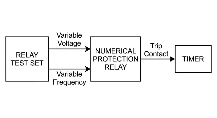
10. Testing Volts-Per-Hertz Protection Relays
Testing ANSI 24 relays requires a test set capable of varying both voltage magnitude and frequency simultaneously. Standard relay test sets from manufacturers like Omicron, Doble, Megger, and Manta Test Systems have this capability.
10.1 Test Procedure
- Verify the pickup level: Apply rated voltage at rated frequency (1.00 pu V/Hz). Slowly increase the voltage while keeping the frequency constant until the relay picks up. Record the pickup voltage. It should match the set pickup level within the relay’s specified accuracy (usually ±1% to ±2%).
- Verify the timing: Apply a V/Hz level above the pickup and measure the relay operating time. Compare it against the expected time from the relay settings. For inverse time characteristics, test at multiple V/Hz levels across the curve.
- Test at reduced frequency: Keep the voltage constant and reduce the frequency. Verify that the relay responds to the increased V/Hz ratio. This confirms that the relay is measuring the ratio and not just the voltage.
- Test the alarm and trip outputs: Confirm that the alarm output activates at the alarm level and the trip output activates at the trip level. Verify correct contact assignments and wiring to the trip coil or control system.
- Verify the reset: Reduce the V/Hz ratio below the pickup level and confirm that the relay resets properly. Check the reset time if applicable.
10.2 Practical Tip
During testing, some relay test sets allow you to create a “state sequence” that simulates a real-world overexcitation event. You can start with normal V/Hz, ramp up to an overexcitation condition, hold it for a defined time, and then return to normal. This test method provides a more realistic verification of the relay behavior.
11. Industry Standards Related to Volts-Per-Hertz Protection
Several industry standards provide guidance on volts-per-hertz protection settings, equipment capabilities, and testing practices:
- IEEE C37.102 – Guide for AC Generator Protection. This standard includes recommendations for ANSI 24 relay application and settings for synchronous generators.
- IEEE C37.91 – Guide for Protecting Power Transformers. This standard discusses overexcitation protection for power transformers.
- IEEE C57.12.00 – General Requirements for Liquid-Immersed Distribution, Power, and Regulating Transformers. This standard defines overexcitation limits for transformers.
- IEEE C50.13 – Standard for Cylindrical-Rotor Synchronous Generators. It provides overexcitation capability limits for large generators.
- IEC 60034-1 – Rotating Electrical Machines, Part 1: Rating and Performance. This international standard covers generator operating limits including overexcitation.
- NERC PRC Standards – In North America, NERC reliability standards address generator protection requirements, including settings that affect V/Hz protection coordination during system disturbances.
12. Conclusion
Volts-per-hertz protection is a fundamental protective function for generators, power transformers, and synchronous condensers. It guards the magnetic core against overexcitation, which can cause rapid thermal damage to the equipment. The ANSI 24 relay monitors the ratio of voltage to frequency and operates when this ratio exceeds safe limits defined by the equipment manufacturer.
Every protection engineer working with generators and power transformers should be comfortable with ANSI 24 relay settings, coordination, and testing. The concepts covered in this guide provide a solid foundation for applying volts-per-hertz protection in real power systems.
13. Frequently Asked Questions (FAQs)
The ANSI 24 relay protects against overexcitation of transformers and generators. It monitors the volts-per-hertz ratio and trips when the ratio exceeds safe limits, preventing thermal damage to the magnetic core.
No. ANSI 59 only monitors voltage magnitude and does not account for frequency changes. A condition with normal voltage but low frequency would not be detected by ANSI 59 but would be detected by ANSI 24. Both protections are needed.
Under normal operating conditions, the V/Hz ratio is approximately 1.00 pu. Most equipment can operate continuously at up to 1.05 pu without damage.
Common causes include AVR malfunction, load rejection, operation in manual excitation mode, and startup or shutdown conditions where the frequency is below the rated value.
You need a relay test set that can vary both voltage and frequency. Apply different V/Hz ratios and measure the relay’s pickup level and operating time. Verify that the relay responds to both overvoltage and underfrequency conditions.
V/Hz protection is primarily applied to large power transformers and generators. Distribution transformers are generally not equipped with individual ANSI 24 relays because the cost is not justified for smaller units.