Every three-phase power system is designed to operate in a balanced condition. The three voltages and currents are equal in magnitude and displaced by 120 degrees from each other. However, faults, equipment failures, and system abnormalities can disturb this balance. An unbalanced condition gives rise to negative sequence components that can cause serious damage to electrical equipment, especially rotating machines like generators and motors.
Negative sequence protection is a protective relaying scheme that detects these unbalanced conditions and takes appropriate action to isolate or alarm the affected equipment. Generators, large motors, and transmission lines are particularly vulnerable to negative sequence currents. Even a small percentage of unbalance can lead to overheating, rotor damage, and reduced equipment lifespan. This makes negative sequence protection a necessary part of any power system protection scheme.
In this technical guide, we will discuss everything you need to know about negative sequence protection, including its working principle, types, applications, relay settings, coordination strategies, testing methods, and relevant industry standards. Practical examples are included throughout to help you apply these concepts in real-world scenarios confidently.
1. What are Negative Sequence Components?
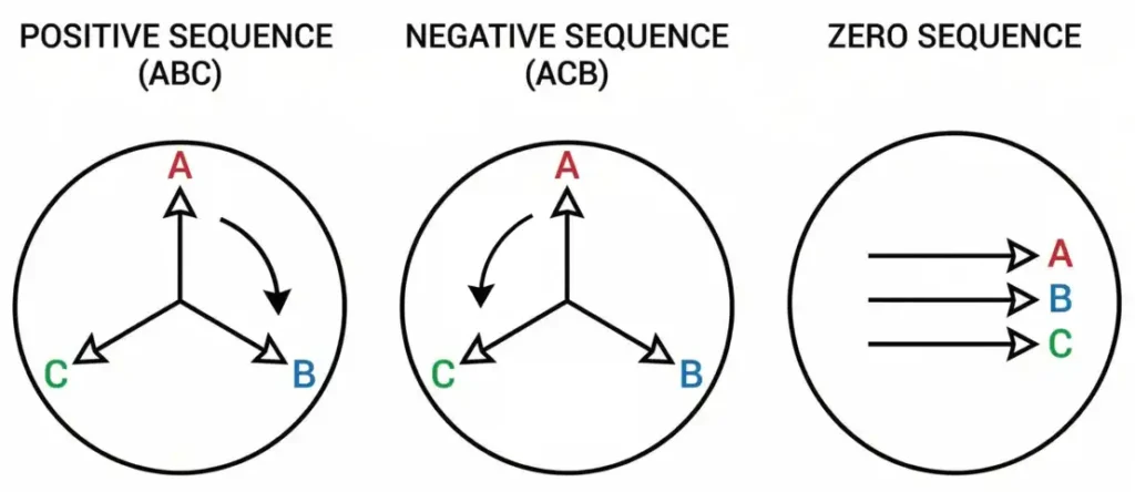
To understand negative sequence protection, you first need to understand symmetrical components. In 1918, Charles Fortescue introduced the method of symmetrical components. This method breaks down any unbalanced set of three-phase quantities into three balanced sets:
- Positive Sequence – Three phasors of equal magnitude, 120 degrees apart, rotating in the normal (ABC) direction.
- Negative Sequence – Three phasors of equal magnitude, 120 degrees apart, rotating in the reverse (ACB) direction.
- Zero Sequence – Three phasors of equal magnitude and zero phase displacement, all rotating together.
In a perfectly balanced system, only positive sequence components exist. Negative sequence components appear during unbalanced conditions such as single line-to-ground faults, line-to-line faults, open conductors, and unbalanced loading.
Practical Example: Suppose a 13.8 kV distribution feeder experiences a single line-to-ground fault. The fault current is not equal in all three phases. Applying symmetrical component analysis, you will find that positive, negative, and zero sequence components all exist during this fault. The negative sequence component is what negative sequence relays detect and respond to.
2. Why is Negative Sequence Current Dangerous?
Negative sequence currents rotate in the opposite direction to the rotor of a generator or motor. This reverse-rotating magnetic field interacts with the rotor and induces currents at twice the system frequency (120 Hz for a 60 Hz system or 100 Hz for a 50 Hz system) in the rotor body, retaining rings, slot wedges, and damper windings.
These double-frequency currents cause rapid and localized heating of the rotor surface. The rotor is not designed to carry these currents for extended periods. If the negative sequence current persists, it can lead to:
- Rotor overheating and thermal damage
- Melting of rotor slot wedges and retaining rings
- Deformation of the rotor body
- Bearing damage due to uneven magnetic forces
- Vibration and mechanical stress
The thermal damage from negative sequence currents follows an \(I^2 t\) characteristic. This means that even a moderately small negative sequence current can cause damage if it persists long enough. Conversely, a large negative sequence current will cause damage in a very short time.
Practical Example: A 100 MVA steam turbine generator has a continuous negative sequence current rating \((I_2)\) of 8% of the rated current. If an unbalanced fault causes 25% negative sequence current, the generator can only withstand this condition for a few seconds before rotor damage begins. The negative sequence relay must operate fast enough to trip the generator before this thermal limit is exceeded.
3. How Negative Sequence Protection Works
Negative sequence protection operates by measuring the negative sequence component of current \((I_2)\) or voltage \((V_2)\) using sequence filters or digital signal processing. The relay extracts the negative sequence component from the three-phase current or voltage inputs and compares it against preset thresholds.
3.1 Working Principle
- Three-phase current transformers (CTs) or voltage transformers (VTs) supply the relay with current and voltage signals.
- The relay applies symmetrical component transformation algorithms to extract the negative sequence component.
- The extracted \(I_2\) value is compared against pickup settings.
- If \(I_2\) exceeds the pickup level, the relay starts timing based on the \(I^2 t\) thermal characteristic of the protected equipment.
- If the thermal limit is reached, the relay issues a trip command to the circuit breaker.
Modern microprocessor-based relays perform this extraction digitally using Discrete Fourier Transform (DFT) or other filtering techniques. Older electromechanical relays used analog filter networks built from resistors, capacitors, and inductors to separate the negative sequence component.
4. ANSI Device Numbers for Negative Sequence Protection
The IEEE/ANSI standard device numbering system assigns specific numbers to negative sequence protective functions:
| ANSI Code | Function |
|---|---|
| 46 | Negative Sequence Current Relay (Phase Balance Current Relay) |
| 60 | Voltage or Current Balance Relay (sometimes used for negative sequence voltage detection) |
| 47 | Negative Sequence Voltage Relay (Phase Sequence Voltage Relay) |
4.1 ANSI 46 – Negative Sequence Overcurrent Relay
The ANSI 46 relay is the primary protective device for detecting negative sequence current. It is used to protect generators, motors, and other equipment from the effects of unbalanced currents. This relay is most commonly applied on:
- Synchronous generators
- Large induction motors
- Synchronous condensers
- Transmission lines and buses (as backup protection)
The ANSI 46 relay can be set with two stages:
- Alarm stage: A lower threshold that activates an alarm, allowing operators to investigate and correct the unbalance before it causes damage.
- Trip stage: A higher threshold or I²t accumulation that trips the breaker to protect the equipment.

4.2 ANSI 47 – Negative Sequence Voltage Relay
The ANSI 47 relay monitors the voltage for negative sequence components. It is often used to detect system-wide voltage unbalance, incorrect phase rotation, or blown fuses on voltage transformer circuits. This relay is applied on:
- Bus sections
- Generator terminals
- Motor feeders
- Power quality monitoring systems
Practical Example: A large cement plant has a 5,000 HP induction motor driving a ball mill. The motor protection relay includes ANSI 46 negative sequence overcurrent protection. The relay is set to alarm at 5% \(I_2\) and trip at 10% \(I_2\) with an inverse time curve. One day, a single fuse blows on the 4.16 kV supply feeder, creating an unbalanced voltage condition. The motor draws unbalanced current with a negative sequence component of 12%. The ANSI 46 function trips the motor within 3 seconds, preventing rotor overheating.
5. Types of Negative Sequence Protection
Negative sequence protection can be categorized based on the quantity being measured and the application.
5.1 Negative Sequence Overcurrent Protection (I₂)
This is the most common form of negative sequence protection. The relay measures the negative sequence current and operates when it exceeds the set threshold. It is used for both generator and motor protection.
The operating characteristic is usually based on the thermal withstand capability of the protected equipment. For generators, this is defined by the \(I_2^2 t = K\) relationship, where \(K\) is a constant specified by the generator manufacturer.
Example values for generators (per IEEE C50.13):
| Generator Type | Continuous I₂ (% of rated) | I₂²t (K value) |
|---|---|---|
| Salient pole (with damper windings) | 10% | 40 |
| Cylindrical rotor (indirectly cooled) | 10% | 30 |
| Cylindrical rotor (directly cooled) | 8% | 10 |
5.2 Negative Sequence Voltage Protection (V₂)
This type monitors the negative sequence voltage at a bus or equipment terminal. It is useful for detecting unbalanced supply conditions that could affect multiple loads simultaneously. Power quality analyzers often use \(V_2\) measurement to quantify voltage unbalance.
5.3 Negative Sequence Directional Protection
Some transmission line protection schemes use negative sequence directional elements. These elements determine the direction of the fault by analyzing the phase angle relationship between \(V_2\) and \(I_2\). This is particularly useful for detecting high-resistance faults and intercircuit faults on double-circuit lines.
5.4 Negative Sequence Differential Protection
Advanced transformer and generator protection relays may include negative sequence differential elements. These compare the negative sequence current on both sides of the protected equipment. A difference above the threshold indicates an internal unbalanced fault.
6. Relay Settings for Negative Sequence Protection
Setting a negative sequence relay correctly requires knowledge of the protected equipment’s thermal limitations, system operating conditions, and coordination requirements.
6.1 Generator Negative Sequence Relay Settings
Step 1: Determine the generator’s negative sequence capability.
Obtain the continuous I₂ rating and I₂²t value (K) from the generator manufacturer or applicable standards.
Step 2: Set the pickup.
The alarm pickup is usually set at 50% of the continuous I₂ rating. The trip pickup is set at or slightly below the continuous I₂ rating.
- Alarm pickup: 0.04 pu (for an 8% continuous rating)
- Trip pickup: 0.08 pu
Step 3: Set the time curve.
The inverse time curve should match the I₂²t = K characteristic. The operating time at any I₂ level is:
t = K / I₂²
For a directly cooled generator with K = 10:
- At I₂ = 0.10 pu: t = 10 / 0.01 = 1000 seconds
- At I₂ = 0.20 pu: t = 10 / 0.04 = 250 seconds
- At I₂ = 0.50 pu: t = 10 / 0.25 = 40 seconds
- At I₂ = 1.00 pu: t = 10 / 1.00 = 10 seconds
Step 4: Set the definite time element (if available).
A definite minimum time is often set to prevent nuisance tripping during transient conditions, such as power swings or switching events. A typical minimum time is 0.25 to 0.5 seconds.

6.2 Motor Negative Sequence Relay Settings
Motor negative sequence relays are simpler to set. The pickup is based on the maximum allowable negative sequence current for the motor. A common setting approach is:
- Pickup: 15-20% of motor rated current (as negative sequence component)
- Time delay: 3-10 seconds definite time, or an inverse time curve
The time setting should coordinate with the motor’s thermal withstand capability and the upstream protection clearing times.
Practical Example: A 2,500 HP, 4.16 kV motor has a full load current of 310 A. The negative sequence relay is set with a pickup of 50 A (approximately 16% of rated current) and a definite time delay of 5 seconds. This allows the relay to ride through momentary switching transients but trip the motor before thermal damage from sustained unbalance.
7. Coordination of Negative Sequence Protection
Negative sequence protection must coordinate with other protective devices in the system to avoid unwanted tripping and to maintain selectivity.
7.1 Coordination with Phase Overcurrent Relays
Phase overcurrent relays (ANSI 50/51) also respond to unbalanced fault currents. The negative sequence relay should be more sensitive than the phase overcurrent relay for detecting low-level unbalance. However, for high-current faults, the phase overcurrent relay should operate first since it can clear the fault faster.
7.2 Coordination with Distance Relays
On transmission lines, negative sequence elements in distance relays (ANSI 21) must coordinate with adjacent zone timers. The negative sequence directional element often serves as a supervisory element rather than a standalone tripping element.
7.3 Coordination with Generator Capability Curves
The negative sequence relay time-current characteristic must fall within the generator’s damage curve. The relay operating time at any I₂ level must be shorter than the time to thermal damage. A safety margin of 10-15% is recommended.
7.4 Coordination with Motor Thermal Relays
For motor applications, the negative sequence relay must coordinate with the motor thermal overload relay (ANSI 49). The thermal relay protects against balanced overload conditions, and the negative sequence relay protects against unbalanced conditions. Both should be set to operate before the motor reaches its thermal limit.
8. Testing Methods for Negative Sequence Relays
Testing negative sequence relays requires specialized three-phase relay test sets capable of producing controlled unbalanced current and voltage signals.
8.1 Test Equipment
A modern three-phase relay test set (such as those from Omicron, Doble, Megger, or Ponovo) can independently control the magnitude and phase angle of each phase current and voltage. This allows the tester to inject specific amounts of negative sequence current or voltage.
8.2 Test Procedure
Test 1: Pickup Verification
- Apply balanced three-phase currents to the relay.
- Gradually increase the unbalance by reducing one phase current or shifting its angle.
- Monitor the negative sequence current calculated by the relay.
- Verify that the relay picks up at the specified I₂ threshold.
Test 2: Timing Verification
- Inject a known negative sequence current above the pickup level.
- Measure the relay operating time.
- Compare the measured time with the calculated time from the I₂²t curve.
- Repeat at multiple I₂ levels to verify the entire curve.
Test 3: Reset Verification
- Inject negative sequence current above pickup to start the relay timer.
- Reduce the current below pickup before the relay trips.
- Verify that the relay resets properly (either instantaneously or following a reset time constant, depending on the relay design).
Test 4: Directional Verification (if applicable)
- Inject negative sequence voltage and current with specific phase angle relationships.
- Verify that the relay correctly identifies the forward and reverse directions.
- Test at multiple angles around the boundary of the directional characteristic.
9. Applications of Negative Sequence Protection
9.1 Generator Protection
Negative sequence protection is one of the most important protection functions for synchronous generators. Generators are highly susceptible to rotor heating from negative sequence currents. The ANSI 46 function is a standard requirement in all generator protection packages.
The IEEE C37.102 standard (Guide for AC Generator Protection) recommends negative sequence protection for all generators. The relay should be set according to the manufacturer’s specified continuous \(I_2\) rating and \(I_2^2 t\) withstand capability.
9.2 Motor Protection
Large induction motors and synchronous motors are also protected by ANSI 46 relays. Motors are sensitive to supply voltage unbalance. Even a 3-5% voltage unbalance can cause 15-25% current unbalance in a motor. This disproportionate effect makes negative sequence current monitoring more effective than voltage monitoring for motor protection.
NEMA MG1 standard specifies that motors should not operate with voltage unbalance exceeding 1%. The derating factor for motors operating under unbalanced conditions drops sharply. At 5% voltage unbalance, a motor must be derated to approximately 75% of its nameplate rating.
9.3 Transmission Line Protection
Distance relays (ANSI 21) on transmission lines sometimes use negative sequence quantities to improve fault detection. Negative sequence overcurrent elements can detect high-impedance faults that may not be detected by conventional phase overcurrent relays. The negative sequence directional element helps determine the fault direction on parallel lines.
9.4 Transformer Protection
Some transformer protection schemes use negative sequence differential elements to detect turn-to-turn faults and other internal winding faults. These faults may not produce enough differential current to operate the conventional differential relay (ANSI 87) but can produce detectable negative sequence components.
9.5 Bus Protection
Bus protection schemes may include negative sequence overcurrent backup elements to detect unbalanced faults that traditional bus differential protection might not catch immediately.
10. Industry Standards for Negative Sequence Protection
Several IEEE, IEC, and NEMA standards govern the application and setting of negative sequence protection:
| Standard | Description |
|---|---|
| IEEE C37.102 | Guide for AC Generator Protection – Provides guidelines for applying ANSI 46 protection on generators |
| IEEE C50.13 | Standard for Cylindrical-Rotor Synchronous Generators – Defines I₂ capability and I₂²t withstand values |
| IEEE C50.12 | Standard for Salient-Pole Synchronous Generators – Similar to C50.13 but for salient pole machines |
| IEEE C37.96 | Guide for AC Motor Protection – Provides guidelines for motor negative sequence protection |
| IEC 60034-1 | Rotating Electrical Machines – Defines unbalanced operation limits |
| NEMA MG1 | Motors and Generators – Specifies voltage unbalance limits and derating factors |
| IEEE C37.2 | Standard for Electrical Power System Device Function Numbers – Defines ANSI 46 and 47 designations |
11. Common Causes of Negative Sequence Conditions
Negative sequence conditions in power systems can be caused by several factors:
- Unbalanced faults – Single line-to-ground faults and line-to-line faults produce negative sequence currents. These are the most common cause.
- Open conductors – A broken conductor or open phase on a transmission or distribution line creates severe unbalance.
- Unbalanced loads – Single-phase loads connected to a three-phase system cause inherent unbalance. Large single-phase loads like electric arc furnaces and railroad traction systems are notable examples.
- Blown fuses – A blown fuse on one phase of a capacitor bank or voltage transformer circuit creates unbalance.
- Asymmetrical transformer tap settings – Incorrect or unequal tap positions on transformer phases can cause voltage unbalance.
- Untransposed transmission lines – Long transmission lines without proper transposition have unequal impedances per phase, causing negative sequence voltage drops.
12. Difference Between Negative Sequence and Zero Sequence Protection
It is common for engineers to confuse negative sequence protection with zero sequence protection. Here is a clear comparison:
| Feature | Negative Sequence (I₂) | Zero Sequence (I₀) |
|---|---|---|
| Caused by | Unbalanced phase-to-phase or phase-to-ground faults, open conductors | Ground faults |
| Rotation | Reverse rotation (ACB) | No rotation (all in phase) |
| ANSI Code | 46 (current), 47 (voltage) | 50N/51N (ground overcurrent), 59N (ground overvoltage) |
| Primary protection for | Generators, motors (rotor heating) | Ground faults on lines, transformers, buses |
| Measurement | Calculated from three-phase quantities | Measured directly from residual CT or neutral CT |
13. Conclusion
Negative sequence protection is a fundamental part of power system protection engineering. It guards generators, motors, and other equipment against the damaging effects of unbalanced currents. The ANSI 46 and ANSI 47 relay functions detect negative sequence current and voltage respectively and operate to alarm or trip before thermal damage occurs.
The correct application of negative sequence protection requires a solid understanding of symmetrical components, equipment thermal limits, relay setting calculations, and coordination with other protection elements. Standards like IEEE C37.102, IEEE C50.13, and IEEE C37.96 provide the framework for proper application.
14. Frequently Asked Questions (FAQs)
The ANSI code for negative sequence current protection is 46. It is also called the phase balance current relay. The ANSI code for negative sequence voltage protection is 47.
Negative sequence current creates a magnetic field that rotates in the opposite direction to the rotor. This reverse-rotating field induces double-frequency currents in the rotor body, causing rapid localized heating. The rotor is not designed to carry these currents, so even moderate levels can cause thermal damage.
The I₂²t value (also called the K value) represents the thermal withstand capability of a generator’s rotor against negative sequence currents. The relay operating time at any negative sequence current level is calculated as t = K / I₂². This formula shapes the inverse time-current curve of the ANSI 46 relay.
Yes. A single open conductor causes severe current unbalance, which produces a large negative sequence component. The ANSI 46 relay will detect this condition and operate accordingly.
The ANSI 46 relay measures negative sequence current, and it is primarily used for equipment protection (generators, motors). The ANSI 47 relay measures negative sequence voltage and is used for detecting system voltage unbalance, incorrect phase rotation, or blown VT fuses.
A three-phase relay test set is used to inject controlled unbalanced currents into the relay. The tester verifies the pickup threshold by gradually increasing the unbalance and measures the operating time at different I₂ levels. The measured values are compared against the relay settings and the equipment’s thermal withstand curve.
For small motors (below 500 HP), negative sequence protection is typically provided by phase unbalance relays or thermal overload relays. Dedicated ANSI 46 protection is more common for large motors above 500 HP or 1000 HP, depending on the facility’s protection philosophy and the motor’s importance.
Per IEEE C50.13, directly cooled cylindrical rotor generators can withstand 8% continuous negative sequence current. Indirectly cooled generators can withstand 10%. Salient pole generators with damper windings can withstand 10%. These values vary by manufacturer, so always check the specific generator’s data sheet.