A run capacitor stores electrical energy even after the power supply has been turned off. This stored charge can remain for hours or even days. If you touch the terminals of a charged capacitor without discharging it first, you risk receiving a painful or even dangerous electric shock. For anyone working with HVAC systems, motors, or electrical panels, knowing how to safely discharge a run capacitor is a non-negotiable skill.
Run capacitors are found in air conditioners, heat pumps, refrigerators, washing machines, and various industrial motor circuits. They help motors run efficiently by maintaining a steady phase angle between voltage and current. However, that same energy storage capability makes them hazardous during maintenance and repair. A capacitor rated at 40 µF and 370 VAC, for example, can hold enough charge to cause burns, muscle contractions, or cardiac issues in extreme cases.
In this technical guide, we will discuss everything you need to know about safely discharging a run capacitor, including its working principle, the hazards of stored charge, required tools, step-by-step discharge procedures, safety standards, common mistakes, and troubleshooting tips. Practical examples are included throughout to help you apply these concepts in real-world scenarios confidently.
1. What is a Run Capacitor and Why Does it Hold a Charge?
A run capacitor is a passive electrical component used in AC motor circuits. It remains in the circuit during the entire operation of the motor. Its primary job is to create a phase shift between the start winding and the run winding of a single-phase motor. This phase shift produces a rotating magnetic field that keeps the motor running smoothly.
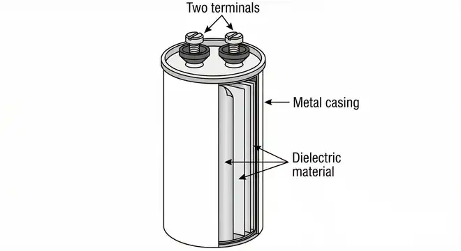
Run capacitors are built using two metallic plates separated by a dielectric material, usually polypropylene film. The dielectric allows the capacitor to store electrical energy in the form of an electric field. The stored energy is calculated using the formula:
\(\boxed{E = \dfrac{1}{2} \times C \times V^2}\)
Where:
- \(E\) = energy in joules
- \(C\) = capacitance in farads
- \(V\) = voltage across the capacitor in volts
For a 45 µF capacitor charged to 370 V, the stored energy is approximately 3.08 joules. That may sound small, but it is more than enough to cause a painful shock, involuntary muscle contraction, or tool damage.
The reason a capacitor retains charge after the circuit is powered off is simple. There is no internal discharge path. Unless the capacitor has a built-in bleed resistor, the voltage across its terminals will remain at or near the last operating voltage for an extended period.
2. Why Discharging a Run Capacitor is Necessary Before Handling
Every time you perform maintenance on a motor, compressor, fan unit, or control panel, you must verify that all capacitors in the circuit are fully discharged. Here is why this step matters.
Electrical shock hazard. A charged capacitor at 370 V or 440 V can deliver a sudden burst of current through your body. This is different from a steady-state shock. The discharge happens in milliseconds, producing a sharp jolt that can throw your hand into nearby sharp objects or cause you to fall from a ladder.
Equipment damage. If a charged capacitor accidentally shorts across a tool or a circuit board, it can burn traces, destroy semiconductors, or weld contact points together.
Arc flash risk. In rare cases, especially with larger capacitors or higher voltage ratings, an accidental short can produce a small arc flash. This can burn skin and damage eyesight.
Legal and regulatory compliance. Standards such as ANSI/NFPA 70E (Standard for Electrical Safety in the Workplace) and OSHA 29 CFR 1910.333 require that stored energy be released before work begins on electrical equipment. Failure to follow these standards can result in fines, liability issues, and workers’ compensation claims.
3. Tools and Equipment Required for Safe Capacitor Discharge
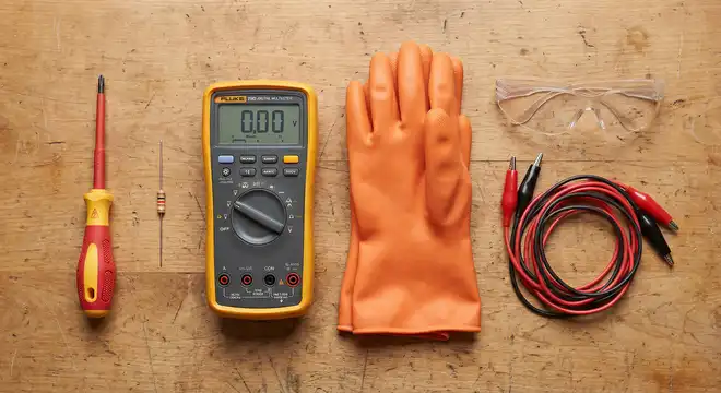
Before you begin, gather the right tools. Using the wrong equipment can make the process more dangerous rather than safer.
1. Insulated screwdriver or discharge tool. A screwdriver with a rated insulation handle (at least 1000 V rated per IEC 60900) is the minimum. However, a purpose-built capacitor discharge tool is preferred.
2. Discharge resistor. A resistor in the range of 10,000 to 20,000 ohms (10 kΩ to 20 kΩ) with a power rating of at least 5 watts is commonly used. This resistor limits the discharge current and prevents sparking. Wire-wound resistors work well for this purpose.
3. Multimeter. A digital multimeter rated CAT III or CAT IV is needed to verify the voltage across the capacitor terminals before and after discharge.
4. Insulated gloves. Class 00 or Class 0 rubber insulating gloves rated per ASTM D120 are recommended for voltages up to 500 V and 1000 V respectively.
5. Safety glasses. ANSI Z87.1-rated safety glasses protect your eyes from any unexpected sparks.
6. Alligator clip leads (optional). These can hold the discharge resistor across the capacitor terminals hands-free, reducing risk.
4. Step-by-Step Procedure to Safely Discharge a Run Capacitor
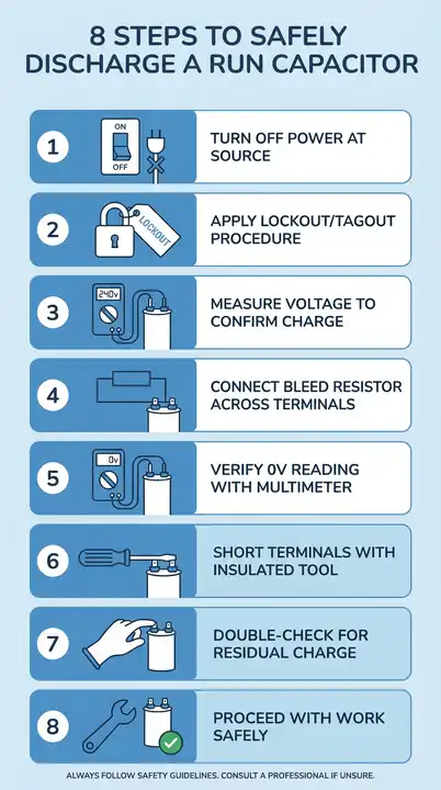
Follow these steps in order. Do not skip any step.
Step 1: Turn Off the Power Supply
Locate the disconnect switch, breaker, or fuse that supplies power to the equipment containing the capacitor. Turn it off. If there is a lockout/tagout (LOTO) procedure in your facility, follow it per ANSI/NFPA 70E and OSHA 29 CFR 1910.147.
Lock the disconnect in the off position and attach your personal tag. This prevents someone else from accidentally re-energizing the circuit while you are working.
Step 2: Verify the Power Is Off
Use your multimeter to test the incoming supply terminals. Set the meter to AC voltage and place the probes on the line and load terminals of the disconnect. The reading should be 0 V or very close to it.
Do not rely on the breaker position alone. Breakers can fail, and labels can be wrong. Always verify with a meter.
Step 3: Access the Capacitor
Open the electrical panel, access cover, or capacitor housing. Run capacitors in HVAC systems are usually located near the compressor or condenser fan motor. They are oval or round metal cans with two or three terminals on top.
Practical example: On a residential air conditioner, the run capacitor is inside the outdoor condensing unit. You will need to remove the access panel on the side of the unit to reach it.
Step 4: Measure the Voltage Across the Capacitor Terminals
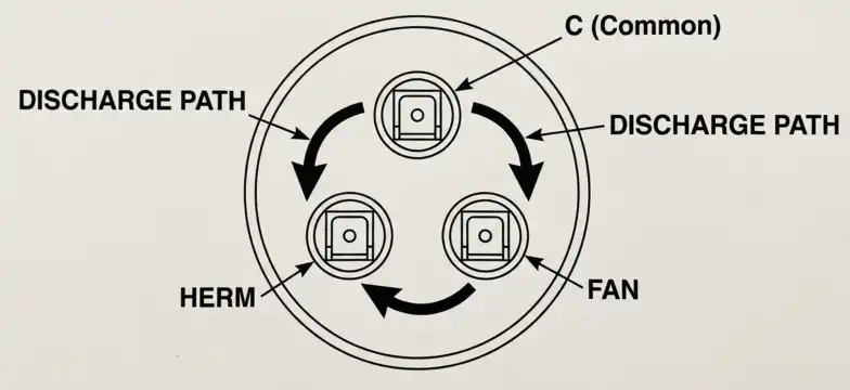
Before touching anything, set your multimeter to AC voltage (since run capacitors operate on AC circuits). Place one probe on each terminal of the capacitor. If the capacitor is a dual-run type (with three terminals labeled C, FAN, and HERM), measure between C and HERM, then between C and FAN.
Record the voltage. A reading of even 10 V or higher means the capacitor is still charged and must be discharged.
Step 5: Connect the Discharge Resistor
Take your discharge resistor (for example, a 20 kΩ, 5-watt resistor) and connect it across the capacitor terminals. You can do this by holding the resistor leads with insulated pliers or by using alligator clip leads.
The resistor creates a controlled path for the stored charge to dissipate as heat. The time constant for discharge is:
\(\tau = R \times C\)
For a 20 kΩ resistor and a 45 µF capacitor:
\(\tau = 20,000 \times 0.000045 = 0.9 \text{ seconds}\)
After 5 time constants (\(5\tau = 4.5 \text{ seconds}\)), the capacitor is considered fully discharged (voltage drops to less than 1% of the initial value).
Step 6: Verify the Capacitor Is Discharged
After holding the resistor across the terminals for at least 10 seconds (to provide a good safety margin), remove the resistor and measure the voltage again with your multimeter.
The reading should be 0 V or less than 1 V. If the voltage is still above 1 V, reconnect the resistor and wait longer.
Step 7: Short the Terminals Together
As a final safety step, use an insulated screwdriver to briefly short the capacitor terminals together. This removes any residual charge. You may see a small spark. This is normal if there was a very small remaining charge.
Step 8: Proceed with Your Work
The capacitor is now safe to handle, remove, test, or replace.
5. Practical Example: Discharging a Capacitor on a Residential Air Conditioner
Let us walk through a real-world example.
Scenario: You are replacing a faulty run capacitor on a 3-ton residential air conditioning unit. The unit uses a dual-run capacitor rated at 40/5 µF, 370 VAC.
Step 1: Turn off the air conditioner at the thermostat. Then, turn off the 30-amp disconnect switch located on the wall next to the outdoor unit.
Step 2: Use your multimeter to check for voltage at the contactor terminals inside the unit. Confirm 0 V on all lines.
Step 3: Locate the capacitor. It is mounted vertically with a strap on the side of the electrical compartment. It has three terminals: C (common), FAN, and HERM (hermetic/compressor).
Step 4: Measure the voltage between C and HERM. Your meter reads 280 V. The capacitor is charged.
Step 5: Connect your discharge resistor (20 kΩ, 5 W) between C and HERM. Wait 10 seconds.
Step 6: Remove the resistor. Measure again. The meter reads 0 V.
Step 7: Repeat the process between C and FAN. The meter reads 85 V. Connect the resistor, wait 10 seconds, verify 0 V.
Step 8: Use an insulated screwdriver to briefly short C to HERM, then C to FAN. No sparks. The capacitor is safe to remove.
Step 9: Disconnect the wires, note their positions, remove the old capacitor, install the new one, reconnect the wires, close the panel, restore power, and test the system.
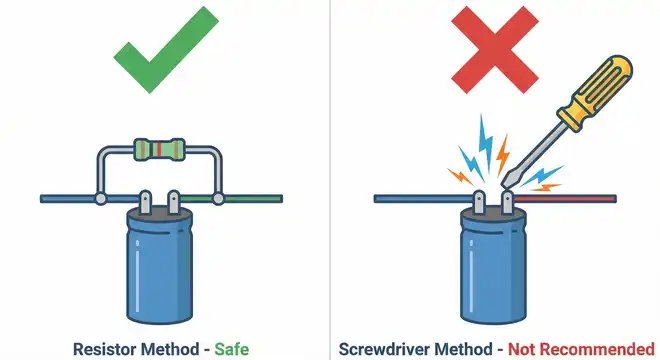
6. The Resistor Method vs. The Screwdriver Method: Which Is Safer?
Many technicians use the “screwdriver across the terminals” method to discharge capacitors. This works, but it has drawbacks.
6.1 Screwdriver Method
- Creates a near-instantaneous discharge
- Produces a loud pop and a visible spark
- Can damage the capacitor terminals through pitting
- Can weld the screwdriver tip to the terminal momentarily
- Sends a high current pulse through the capacitor, which may damage internal components
6.2 Resistor Method
- Provides a controlled, slower discharge
- Produces no spark and no noise
- Does not damage the capacitor or terminals
- Follows best engineering practices
The resistor method is the recommended approach in professional settings. It is the method described in most electrical safety training programs and is consistent with the intent of NFPA 70E hazard reduction principles.
Practical example: Imagine you are replacing a dual-run capacitor on a commercial rooftop HVAC unit. The capacitor is rated at 55 µF and 440 VAC. Using a screwdriver to short this capacitor would create a significant spark and could damage the new capacitor if it was already connected. Using a 20 kΩ resistor, the discharge takes about 5.5 seconds and is completely silent and safe.
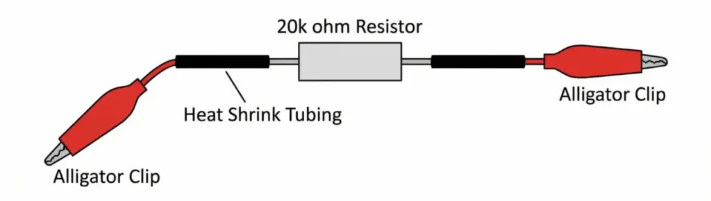
7. Building a Simple Capacitor Discharge Tool
You can build a reliable discharge tool for a few dollars. Here is how.
Materials needed:
- One 20 kΩ, 5-watt wire-wound resistor
- Two insulated alligator clips
- Two pieces of 14 AWG or 16 AWG insulated wire, each about 12 inches long
- Heat shrink tubing
Assembly instructions:
- Solder one wire to each lead of the resistor.
- Cover the solder joints with heat shrink tubing for insulation.
- Attach an alligator clip to the free end of each wire.
- Cover the alligator clip connections with heat shrink tubing.
How to use it:
Clip one lead to each capacitor terminal. Wait 10 seconds. Remove the clips. Verify 0 V with your multimeter.
This tool can be kept in your tool bag and reused for years. It costs less than $5 to build and can prevent costly injuries or equipment damage.
8. Common Mistakes to Avoid
Here are the most frequent errors technicians make when discharging run capacitors.
1. Assuming the capacitor is already discharged. Never assume. Always measure. Some capacitors can hold a charge for days.
2. Using bare hands to touch terminals. Even if you think the capacitor is discharged, wear insulated gloves until you have verified 0 V with a meter.
3. Using a wire or screwdriver without a resistor. A direct short can damage the capacitor, produce dangerous sparks, and send a high current pulse through your tool.
4. Forgetting to check all terminal pairs on a dual-run capacitor. A dual-run capacitor has three terminals (C, FAN, HERM). You need to discharge between C and FAN, and between C and HERM.
5. Not using a properly rated multimeter. A cheap multimeter without proper CAT ratings can fail during measurement, exposing you to voltage. Use a meter rated CAT III 600 V or higher.
6. Skipping lockout/tagout. If someone energizes the circuit while you are working on the capacitor, the capacitor will recharge instantly.
9. How Long Does a Run Capacitor Hold Its Charge?
The duration depends on the discharge path available in the circuit. If the capacitor has a built-in bleed resistor (also called a discharge resistor), the charge will dissipate within a few minutes after power is removed. Most modern run capacitors designed for HVAC applications do include internal bleed resistors.
However, not all capacitors have this feature. Older capacitors, replacement units from different manufacturers, and capacitors used in industrial motor circuits may not have internal bleed resistors.
Even with a bleed resistor present, the safest practice is to assume the capacitor is charged and follow the full discharge procedure every time. A faulty or open bleed resistor will leave the capacitor fully charged.
Rule of thumb: If more than 5 minutes have passed since the circuit was de-energized, the charge may have partially dissipated. But partial is not the same as zero. Always verify with a meter.
10. Conclusion
Discharging a run capacitor before handling it is a basic but important safety procedure. The stored energy in a charged capacitor can cause painful shocks, burns, equipment damage, and in extreme cases, serious medical emergencies. The correct method involves turning off and locking out the power supply, measuring the voltage across the capacitor, applying a discharge resistor across the terminals, and verifying 0 V with a multimeter afterward.
The resistor discharge method is safer and more professional than the screwdriver short-circuit method. It prevents sparking, terminal damage, and sudden current surges. Building a simple discharge tool costs less than five dollars and takes only a few minutes.
11. Frequently Asked Questions (FAQs)
Yes. A run capacitor can hold its charge for hours or even days after the power is turned off. Always measure the voltage and discharge the capacitor before touching it.
A resistor in the range of 10 kΩ to 20 kΩ with a power rating of at least 5 watts is suitable for most run capacitors rated up to 440 VAC.
Using a 20 kΩ resistor on a 45 µF capacitor, the discharge takes about 4.5 seconds (5 time constants). Allow at least 10 seconds for a safe margin.
It works, but it is not recommended. The sudden short circuit creates sparks, can damage the capacitor terminals, and sends a high-current pulse through the tool. Use a resistor instead.
No. Many modern HVAC capacitors include internal bleed resistors, but older or industrial capacitors may not. Always assume the capacitor is charged and follow the full discharge procedure.
Any voltage above 50 V is considered hazardous per NFPA 70E. However, even voltages below 50 V can be dangerous if the capacitance is large enough to deliver a high-energy discharge.
Yes, a standard incandescent light bulb can serve as a discharge load. The bulb will flash briefly as it absorbs the stored energy. However, a resistor provides more consistent and predictable results.
You risk getting shocked while disconnecting the wires from the old capacitor. The stored charge can arc between the terminal and your tool or hand.
Discharge between the C terminal and the HERM terminal, then separately between the C terminal and the FAN terminal. Each section must be discharged independently.