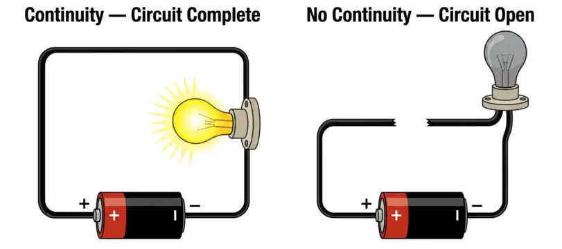
Every electrical circuit needs a complete path for current to flow from the source to the load and back. If there is a break anywhere in this path, the circuit will not work. A continuity test is the most basic and most frequently used test in electrical work. It tells you if a wire, cable, fuse, switch, or any conductor has a complete and unbroken path for electric current.
Electricians, maintenance technicians, and electrical engineers perform continuity tests daily. This test helps identify broken wires, blown fuses, faulty switches, and bad connections. It is also used to verify that a newly installed circuit is wired correctly before energizing it. The tool most commonly used for this test is a digital multimeter set to the continuity mode. The test itself is simple, but the information it provides is extremely valuable for troubleshooting and safety verification.
In this technical guide, we will discuss everything you need to know about continuity testing, including its working principle, methods, tools, applications, relevant standards, and common mistakes. Practical examples are included throughout to help you apply these concepts in real-world scenarios confidently.
1. What is a Continuity Test?
A continuity test checks if there is a complete electrical path between two points in a circuit. The word “continuity” means an unbroken connection. If current can flow freely between the two test points, the circuit has continuity. If the path is broken, there is no continuity.
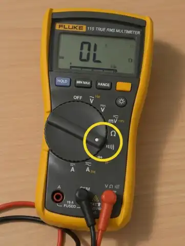
This test is always performed on de-energized circuits. You must turn off the power before performing a continuity test. The testing instrument sends a small current through the conductor being tested. If the current passes through successfully, the meter shows a low resistance reading, and most multimeters also produce an audible beep. If the current cannot pass through, the meter displays “OL” (open loop), meaning the path is broken.
A continuity test does not measure how well a circuit performs under load. It simply confirms that a path exists. Think of it like checking if a water pipe is clear before turning on the faucet. You are not measuring water pressure. You are just making sure the pipe is not blocked.
2. How Does a Continuity Test Work?
The working principle of a continuity test is straightforward. The multimeter or continuity tester has an internal battery. This battery sends a small DC current through the test leads and into the conductor being tested.
Here is the step-by-step process:
- The meter generates a small voltage (usually 1 to 3 volts DC) from its internal battery.
- This voltage pushes a small current through the test leads.
- One test lead is placed at one end of the conductor. The other test lead is placed at the other end.
- If the conductor is intact, the small current flows through it and completes the circuit inside the meter.
- The meter detects this current flow and shows a low resistance value on the display.
- Most digital multimeters also activate a built-in buzzer to produce a beep sound.
If the conductor is broken, the current cannot flow. The meter displays “OL” or “1” on the screen, which means the resistance is infinitely high. No beep is produced.
The threshold resistance for the buzzer to sound varies by meter manufacturer. Most meters beep if the resistance is below 20 to 50 ohms. Some professional-grade meters allow you to set a custom threshold.
3. Tools Used for Continuity Testing
Several tools can perform continuity tests. Each has its own advantages depending on the situation.
3.1 Digital Multimeter (DMM)
The digital multimeter is the most common tool for continuity testing in professional electrical work. Most DMMs have a dedicated continuity mode marked with a speaker or diode symbol on the dial. A quality digital multimeter is a must-have tool for any electrician or engineer.
3.2 Analog Multimeter
Older analog meters can also test continuity using the resistance (ohms) setting. The needle deflects toward zero if there is continuity. These meters are less common today but still found in some workshops.
3.3 Dedicated Continuity Tester
This is a simple device with a battery, a test lead, and a light or buzzer. It is inexpensive and easy to use. However, it does not give you a resistance reading. It only tells you if the path is complete or broken.
3.4 Insulation Resistance Tester (Megger)
A megger is used for testing insulation resistance, but it can also identify continuity issues. It applies a higher voltage (250V, 500V, or 1000V) and is used for testing cables and motor windings. This is a more advanced and specialized tool.
3.5 Low-Resistance Ohmmeter (DLRO)
For testing connections with very low resistance values, such as busbar joints and cable splices, a DLRO is used. This instrument measures in micro-ohms and milli-ohms. It is common in substation commissioning and maintenance.
4. Step-by-Step Procedure for a Continuity Test
Follow these steps to perform a continuity test safely and accurately.
Step 1: De-energize the circuit. Turn off the power supply and use a voltage tester to confirm there is no voltage present. Follow proper lockout/tagout (LOTO) procedures.
Step 2: Isolate the component. If possible, disconnect the wire or component from the rest of the circuit. This prevents parallel paths from giving you a false reading.
Step 3: Set the multimeter to continuity mode. Turn the dial to the continuity symbol (it looks like a sound wave or a diode symbol with dots).
Step 4: Test the meter leads. Touch the two test leads together. The meter should beep and show a reading close to zero ohms. This confirms the meter is working.
Step 5: Place the test leads on the two points. Put one lead on each end of the wire, fuse, switch, or component you are testing.
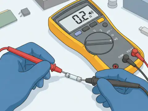
Step 6: Read the result. If the meter beeps and shows low resistance, the component has continuity. If the meter shows “OL” and does not beep, the component is open or broken.
Step 7: Record the result. Document your findings for maintenance records or commissioning reports.
5. Practical Examples of Continuity Testing
Example 1: Testing a Fuse
You suspect a fuse has blown in a control panel. Remove the fuse from its holder. Set your multimeter to continuity mode. Place one test lead on each end of the fuse. If the meter beeps, the fuse is good. If it shows “OL,” the fuse is blown and needs replacement.
Example 2: Testing a Light Switch
A light does not turn on, and you want to check if the switch is faulty. De-energize the circuit. Remove the switch from the wall box. Set your meter to continuity. Touch the leads to the two terminals of the switch. Flip the switch on. If you get a beep, the switch is good. Flip it off. The beep should stop. If there is no beep in either position, the switch is defective.
Example 3: Testing a Long Cable Run
You have pulled a new cable through conduit, and you need to verify it before termination. At one end, twist the two conductors together. Go to the other end and test between the two conductors. A beep confirms the cable is intact from end to end. This is a common practice in commercial and industrial electrical installations.
Example 4: Testing a Motor Winding
You want to check if a motor winding is open. Disconnect the motor from the circuit. Test between each pair of motor terminals (U-V, V-W, U-W for a three-phase motor). Each pair should show continuity and similar resistance values. An open reading on any pair indicates a broken winding.
6. Continuity Test vs. Insulation Resistance Test
These two tests are often confused. They serve very different purposes.
A continuity test checks if a conductor provides a complete path for current. You want the resistance to be low. A good result means the conductor is intact.
An insulation resistance test checks if the insulation around a conductor is in good condition. You want the resistance to be high. A good result means the insulation is not degraded or damaged.
| Feature | Continuity Test | Insulation Resistance Test |
|---|---|---|
| Purpose | Verify complete conductor path | Verify insulation integrity |
| Desired Result | Low resistance (good) | High resistance (good) |
| Test Voltage | 1 to 3V DC | 250V to 5000V DC |
| Tool | Multimeter | Megger |
| Performed On | Conductors, switches, fuses | Cable insulation, motor windings |
Both tests are performed on de-energized circuits. Both are standard procedures during electrical installation and maintenance. A good electrical testing program includes both.
7. Common Mistakes During Continuity Testing
Even experienced electricians can make mistakes during continuity testing. Here are the most common ones to avoid.
Testing an energized circuit: This is the most dangerous mistake. A continuity test must only be done on a de-energized circuit. Testing a live circuit can damage the meter and create a safety hazard.
Not isolating the component: If the component being tested is still connected to the rest of the circuit, parallel paths can give you a false continuity reading. Always disconnect or isolate the component before testing.
Dirty or corroded test leads: Poor contact between the test leads and the conductor can cause intermittent or false open readings. Keep your test leads clean and replace them if the tips are worn.
Ignoring resistance values: Some technicians rely only on the beep and do not look at the resistance reading. A beep with a resistance of 0.5 ohms is very different from a beep with 45 ohms. The resistance value gives you additional information about the quality of the connection.
Using the wrong meter setting: Accidentally setting the meter to voltage mode instead of continuity mode can result in no reading and confusion. Always verify your meter setting before testing.
8. Applications of Continuity Testing in Different Industries
Continuity testing is used across many industries and applications.
Residential Electrical Work: Electricians test new wiring runs, verify switch loops, and check outlet connections during rough-in and final inspections.
Commercial Buildings: Building maintenance teams use continuity tests to troubleshoot lighting circuits, HVAC controls, fire alarm wiring, and emergency power systems.
Industrial Plants: Maintenance electricians test motor circuits, control wiring, PLC I/O circuits, and power distribution connections. Continuity testing is part of preventive maintenance programs in manufacturing facilities.
Automotive Electrical Systems: Auto electricians test wiring harnesses, sensors, and connectors in vehicles. A broken wire in a wiring harness is a common cause of electrical faults in cars.
Aerospace and Aviation: Aircraft maintenance technicians perform continuity tests on flight control wiring, communication systems, and navigation equipment. These tests are documented and audited per FAA regulations.
Telecommunications: Network technicians test cable pairs for continuity before and after installation. This is standard practice for copper telephone and data cables.
Power Utilities: Utility workers test grounding conductors, substation wiring, and protective relay circuits. Continuity of grounding systems is especially important for personnel safety.
9. Conclusion
A continuity test is one of the most fundamental tests in electrical work. It confirms that a conductor, switch, fuse, or connection provides a complete path for current flow. The test is simple to perform, requires basic tools, and provides immediate results. Every electrician, technician, and electrical engineer should be proficient in performing and interpreting continuity tests.
This test plays a major role in installation verification, troubleshooting, and preventive maintenance across residential, commercial, industrial, and utility applications. Following proper procedures and safety precautions is necessary every time you pick up a meter. Always de-energize the circuit, isolate the component, and verify your meter is functioning before testing.
10. Frequently Asked Questions (FAQs)
No. A continuity test must only be performed on a de-energized circuit. Testing a live circuit can damage your meter and create a dangerous situation.
A continuity test is actually a type of resistance test. The meter measures resistance and activates a buzzer if the resistance is below a set threshold. A standard resistance test gives you only a numerical value without the audible indication. Both use the same measurement principle.
This can happen if the wire is still connected to other components in the circuit that create a parallel path. Disconnect the wire from the circuit and test it independently for an accurate result.
For most practical purposes, a reading below 1 ohm indicates good continuity for short conductors and connections. For longer cable runs, calculate the expected resistance based on wire gauge and length. Any reading well above the expected value indicates a problem.
Yes. If two wires that should be isolated from each other show continuity between them, there is a short circuit. This is a common use of continuity testing in troubleshooting.
No. Any standard digital multimeter with a continuity function can perform this test. For professional electrical work, use a meter that meets safety standards such as IEC 61010 with appropriate CAT ratings.
For new installations, continuity tests are performed before the system is energized. For existing systems, they should be part of your regular preventive maintenance program.
A basic continuity test may not detect high-resistance connections because the buzzer only activates below a certain threshold. Use the resistance measurement mode for a numerical reading if you suspect a high-resistance joint.