Transformer polarity is one of those topics that many engineers and technicians overlook during installation and commissioning. It seems like a small detail. But getting transformer polarity wrong can lead to serious problems in an electrical power system. From blown fuses to damaged equipment and incorrect metering, the consequences are real and costly.
Many field incidents and equipment failures have been traced back to incorrect polarity connections. These failures could have been avoided with proper testing and verification before energization.
In this technical guide, we will discuss in detail what happens if transformer polarity is wrong, covering its effects on parallel operation, protective relaying, metering, voltage regulation, and winding connections. Practical examples are included throughout to help you apply these concepts in real-world scenarios confidently.
1. What is Transformer Polarity?
Before we look at the consequences, let us briefly recap what transformer polarity means.
Transformer polarity indicates the instantaneous direction of the induced voltage on the secondary winding relative to the primary winding. It is marked using dot convention or by labeling terminals as H1, H2 (primary) and X1, X2 (secondary).
There are two types of polarity:
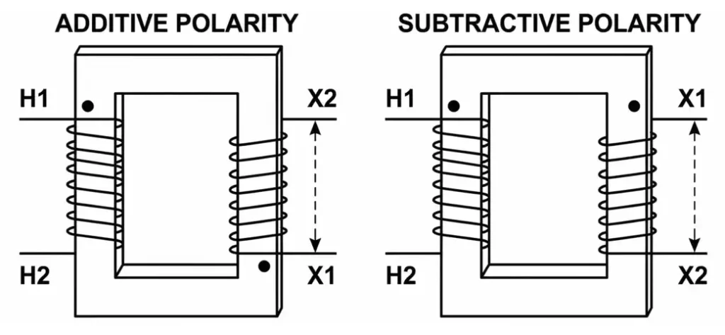
- Additive Polarity: H1 and X1 are on opposite sides of the transformer. The voltages add up when measured across H1 and X2.
- Subtractive Polarity: H1 and X1 are on the same side. The voltages subtract when measured across H1 and X2.
As per ANSI/IEEE C57.12.00, distribution transformers rated 200 kVA and below with voltage ratings of 8660 V and below use additive polarity. Power transformers and larger units use subtractive polarity.
Now, let us look at what goes wrong if this polarity is not connected correctly.
2. Effect on Parallel Operation of Transformers
One of the most dangerous consequences of wrong polarity shows up during parallel operation. Transformers are connected in parallel to share load and increase system reliability. For successful parallel operation, several conditions must be met. Same polarity is one of the most important conditions.
If two transformers with opposite polarity markings are connected in parallel, their secondary voltages will oppose each other instead of being in phase. This creates a net voltage difference across the paralleled secondaries. Since the impedance of the transformer windings is very low, even a small voltage difference will drive a very large circulating current between the two transformers.
2.1 Practical Example
Imagine two 480V transformers connected in parallel. If one transformer has correct polarity and the other has reversed polarity, the voltage difference across the parallel connection becomes 480V + 480V = 960V. This 960V drives a massive circulating current through the low-impedance path of both transformer windings. The result is immediate overheating, insulation failure, and likely an explosion or fire.
This is not a theoretical risk. There are documented cases where incorrect polarity during parallel commissioning has destroyed transformers within seconds of energization.
3. Effect on Differential Protection Schemes
Differential protection is the most common protection scheme used for power transformers. It works on the principle of comparing the current entering the transformer with the current leaving it. Under normal conditions, the difference between these two currents (after accounting for the turns ratio and CT connections) should be nearly zero. The relay only operates if it detects a difference above a set threshold, which indicates an internal fault.
If the CT polarity or the transformer polarity is wrong in this scheme, the relay will see a false differential current even during normal load conditions. This means the relay will trip the transformer immediately upon energization, even though there is no actual fault.
On the other hand, a reversed polarity connection could also cause the relay to remain stable during a real internal fault. The fault current and the through current could cancel each other out in the relay’s operating coil. This is an extremely dangerous situation because the protection will fail exactly when it is needed.
According to ANSI/IEEE C37.91 (Guide for Protecting Power Transformers), correct polarity verification of both the power transformer and the associated current transformers is a mandatory step before commissioning differential relays.
3.1 Practical Example
A 20 MVA, 132/33 kV power transformer is protected by a percentage differential relay (87T). During commissioning, if the CT on the 33 kV side is connected with reversed polarity, the relay will see the secondary current as flowing in the same direction as the primary current instead of the opposite direction. The relay interprets this as a fault current and trips the breaker. Engineers then spend hours troubleshooting a “faulty” relay, only to discover the CT leads were swapped.
4. Effect on Metering and Instrumentation
Incorrect transformer polarity directly affects metering accuracy. Current transformers (CTs) and voltage transformers (VTs or PTs) are instrument transformers. They step down high currents and voltages to measurable levels for meters, relays, and SCADA systems.
If a CT or VT is connected with wrong polarity, the measured values will have a 180-degree phase shift. This affects wattmeters, VAR meters, power factor meters, and energy meters.
A wattmeter, for example, calculates power using the product of voltage and current, considering the phase angle between them. If the CT polarity is reversed, the current signal is shifted by 180 degrees. This makes the wattmeter read negative power, or in the case of a single-phase meter, it may simply read lower than the actual value or run backward.
4.1 Practical Example
A factory installs a new revenue-grade energy meter on a 4160V feeder. The CT on Phase B is accidentally connected with reversed polarity. The meter now shows a lower energy consumption because the Phase B power is being subtracted instead of added. Over months, this error leads to significant billing discrepancies. The utility loses revenue and the customer may face back-billing when the error is eventually discovered.
In revenue metering, even a small polarity error can result in thousands of dollars in lost or incorrect billing over time. That is why ANSI C12.1 (Code for Electricity Metering) requires polarity verification as part of metering installation and testing.
5. Effect on Voltage Regulation and Tap Changer Operation
Transformers used in power distribution often have tap changers for voltage regulation. The automatic voltage regulator (AVR) monitors the output voltage and adjusts the tap position to maintain a steady voltage level at the load end.
If the polarity of the voltage sensing transformer (VT) feeding the AVR is reversed, the regulator will receive an inverted signal. It will interpret a voltage rise as a voltage drop and vice versa. The tap changer will then move in the wrong direction, making the voltage problem worse instead of correcting it.
5.1 Practical Example
A 13.8 kV distribution feeder uses a step voltage regulator with an automatic control system. The VT connected to the regulator’s control circuit has reversed polarity. The load increases and the voltage drops. The regulator senses this drop as a rise (due to the inverted signal) and lowers the tap position to reduce voltage further. The voltage continues to drop until it reaches an unacceptable level. Customers on that feeder experience brownouts and equipment damage.
This type of problem is hard to diagnose remotely because the regulator appears to be working correctly from the SCADA display. Only a field verification of VT polarity reveals the root cause.
6. Effect on Three-Phase Transformer Bank Connections
Three single-phase transformers are often connected together to form a three-phase bank in delta-delta, delta-wye, wye-delta, or wye-wye configurations. Correct polarity of each individual transformer is absolutely necessary for the bank to work properly.
If one transformer in a delta-connected bank has reversed polarity, the voltages around the delta loop will not sum to zero as they should. Instead, a net circulating voltage will exist inside the delta. This circulating voltage will drive a large circulating current through the windings, causing overheating and damage.
In an open-delta (V-V) configuration, wrong polarity on either of the two transformers will result in incorrect phase relationships at the output. The three-phase load will receive unbalanced and incorrect voltages, causing motor overheating and erratic operation.
7. Effect on Current Transformer (CT) Circuits
Current transformers have clearly marked polarity indicators. The primary polarity mark (usually H1 or a dot) corresponds to the secondary polarity mark (X1 or P1). These markings indicate the direction of current flow at any instant.
If a CT is installed with reversed polarity in a protective relay circuit, the relay receives an inverted current signal. The consequences depend on the type of protection scheme:
- Overcurrent Relays (50/51): Reversed CT polarity does not affect magnitude-only overcurrent relays since they measure current magnitude regardless of direction. However, directional overcurrent relays (67) will be severely affected because they rely on the phase angle between voltage and current to determine fault direction.
- Differential Relays (87): As discussed above, reversed CT polarity causes false tripping or failure to trip during actual faults.
- Distance Relays (21): Wrong CT polarity can cause the relay to calculate incorrect impedance values, leading to incorrect zone reach and possible misoperation.
8. Effect on Winding Connections in Auto-Transformers
Auto-transformers share a common winding between the primary and secondary. The voltage regulation in an auto-transformer depends entirely on the correct polarity of the series and common windings.
If the polarity is reversed in an auto-transformer, instead of boosting or bucking the voltage as intended, the transformer will do the opposite. A transformer meant to boost the voltage by 10% will instead reduce it by 10%, or vice versa.
8.1 Practical Example
A 120V to 132V step-up auto-transformer is used to correct low voltage at a remote facility. The series winding is connected with wrong polarity. Instead of adding 12V to the input, it subtracts 12V. The output becomes 108V instead of 132V. The equipment at the facility experiences even worse low-voltage conditions than before.
9. What Are the Physical Warning Signs of Wrong Polarity?
If transformer polarity is wrong and the transformer is energized, the following signs may appear:
- Excessive humming or buzzing sound from the transformer beyond normal levels.
- Rapid temperature rise in the transformer windings and core.
- Blown fuses or tripped breakers immediately upon energization.
- Protective relay operation (especially differential relays) without any apparent fault.
- Incorrect meter readings — negative power, reversed energy registration, or abnormally low readings.
- Smoke or burning smell from the transformer if circulating currents are large enough.
- Unbalanced voltages on the secondary side in three-phase configurations.
If any of these signs appear during commissioning, the transformer should be de-energized immediately and the polarity connections should be verified.
10. How to Avoid Wrong Polarity Connections
Preventing polarity errors requires a systematic approach during installation and commissioning:
- Always perform a polarity test before connecting the transformer to the system. This can be done using the kick test (DC method) or the AC method with a voltmeter.
- Verify terminal markings — Check that H1, H2, X1, X2 labels match the manufacturer’s nameplate drawing.
- Follow the ANSI standard conventions. Refer to ANSI/IEEE C57.12.00 for power transformers and ANSI/IEEE C57.13 for instrument transformers.
- Use phasing equipment to verify phase relationships before paralleling transformers or energizing transformer banks.
- Perform secondary injection testing on all protective relay circuits to verify correct CT and VT polarity before placing the protection in service. This is aligned with ANSI/IEEE C37.91 recommendations.
- Document everything. Create clear wiring diagrams and mark all terminal connections during installation.
11. Industry Standards Related to Transformer Polarity
Here is a summary of the relevant ANSI/IEEE standards:
| Standard | Description |
|---|---|
| ANSI/IEEE C57.12.00 | General requirements for liquid-immersed distribution, power, and regulating transformers. Covers polarity designation. |
| ANSI/IEEE C57.12.90 | Test code for liquid-immersed distribution, power, and regulating transformers. Includes polarity test procedures. |
| ANSI/IEEE C57.13 | Standard for instrument transformers (CTs and VTs). Covers polarity markings and testing. |
| ANSI/IEEE C37.91 | Guide for protecting power transformers. Addresses correct polarity in differential protection schemes. |
| ANSI C12.1 | Code for electricity metering. Requires polarity verification for revenue metering installations. |
12. Conclusion
Getting transformer polarity wrong is not just a minor wiring mistake. It can cause transformer destruction during parallel operation, protection relay malfunction, metering errors, voltage regulation failures, and overheating of three-phase transformer banks. The consequences range from financial losses due to incorrect billing to equipment damage worth hundreds of thousands of dollars.
Every transformer installation and commissioning procedure should include a polarity verification step. This applies to power transformers, distribution transformers, current transformers, and voltage transformers alike. The relevant ANSI/IEEE standards clearly define the polarity conventions and testing methods that engineers and technicians should follow.
A few minutes spent verifying polarity before energization can save weeks of troubleshooting and thousands of dollars in repairs. Make polarity testing a non-negotiable part of your commissioning checklist. It is one of the simplest tests you can perform, and it prevents some of the most damaging errors in electrical power systems.
13. Frequently Asked Questions (FAQs)
Yes. If transformers are paralleled with wrong polarity, the resulting circulating current can be extremely large. This current causes rapid overheating of the windings, which can lead to insulation failure, oil decomposition (in oil-filled transformers), and fire.
A standard non-directional overcurrent relay (50/51) responds to current magnitude only, so it is not affected by polarity direction. However, a directional overcurrent relay (67) uses the phase relationship between voltage and current to determine fault direction. Wrong CT polarity will cause this relay to operate incorrectly.
The simplest method is the DC kick test. Connect a DC source (like a battery) to the primary winding and observe the deflection on an analog voltmeter connected to the secondary. A positive kick on closing the circuit indicates the marked polarity terminal is correct. Alternatively, the AC method involves shorting H1 to X1 and measuring voltage across H2-X2 to determine if the polarity is additive or subtractive.
Yes, it matters if the transformer feeds metering circuits, protective relays, or if it will ever be paralleled with another transformer in the future.
Wrong polarity will not usually cause physical damage to a digital power meter. However, the meter will display incorrect readings. It may show negative power or register energy in the wrong direction.
Neither is better. They are simply conventions. Additive polarity is used for smaller distribution transformers per ANSI standards, and subtractive polarity is used for larger power transformers.
The differential relay will see a false differential current during normal load conditions. This will cause the relay to trip the transformer even though there is no internal fault. Alternatively, it could prevent the relay from tripping during an actual internal fault, which is even more dangerous.