The polarity test of a single phase transformer is a standard electrical test performed during transformer commissioning, installation, and maintenance. This test determines the instantaneous phase relationship between the primary and secondary windings. Getting the polarity right matters because transformers are often connected in parallel or grouped into three-phase banks. A wrong polarity connection can cause large circulating currents, transformer overheating, insulation failure, and even complete equipment damage.
In this technical guide, we will discuss everything you need to know about single phase transformer polarity testing, including terminal identification, types of polarity (additive and subtractive), step-by-step AC voltage test procedure, the DC kick test method, safety precautions, observation tables, and relevant ANSI/IEEE standards. Practical examples are included throughout to help you apply these concepts in real-world scenarios confidently.
1. What is Transformer Polarity?
Transformer polarity is defined as the instantaneous phase relationship between the primary and secondary windings of a transformer at any given moment. It describes which terminals on the primary and secondary sides have the same instantaneous polarity (positive or negative) at a particular instant in time.
In alternating current (AC) systems, the voltage and polarity at transformer terminals are constantly changing as the AC waveform oscillates. However, at any specific instant in time, one terminal carries a positive potential while the other carries a negative potential. The polarity test is a diagnostic procedure that identifies which primary and secondary terminals have matching instantaneous polarities—that is, which terminals are simultaneously positive or simultaneously negative.
1.1 Practical Example of Same & Opposite Polarity
Transformer polarity is important because it determines how transformers behave when connected together or integrated into electrical systems.
Imagine you have two identical 50 kVA, 480V to 240V single-phase transformers that you want to connect in parallel to share the electrical load in a commercial building’s electrical distribution system.
If both transformers have the same polarity (both additive or both subtractive), they work together each supplying 50 amperes to the 240V secondary bus totaling 100 amperes to serve the building’s lighting and equipment loads.
However, if one transformer has additive polarity and the other has subtractive polarity, a large circulating current will flow between them even when there is no load connected to the secondary.
Here’s what happens physically: When the primary voltage reaches +480V on both transformers simultaneously, the transformer with additive polarity produces +240V on terminal X1, while the transformer with subtractive polarity produces -240V on the corresponding terminal position. This creates a 480V potential difference between the two secondary sides, causing a massive circulating current to flow between the transformer secondaries through their interconnecting cables.
Each transformer now carries its share of the load current plus this entire circulating current doubling the actual current flowing through the windings.
This circulating current causes both transformers to overheat due to excessive copper losses, and they can suffer severe damage within hours.
2. Terminal Identification and Marking
Transformer terminals follow standardized naming conventions established by ANSI (American National Standards Institute) and IEEE (Institute of Electrical and Electronics Engineers). The primary standard governing transformer terminal markings and polarity is IEEE C57.12.00 (IEEE Standard for General Requirements for Liquid-Immersed Distribution, Power, and Regulating Transformers).
Primary Winding Terminals: Labeled H1 and H2 (High Voltage side)
Secondary Winding Terminals: Labeled X1 and X2 (Low Voltage side)

Per ANSI/IEEE convention, H1 and X1 always have the same instantaneous polarity. This means that at any instant when H1 is positive, X1 is also positive. This is true for both additive and subtractive polarity transformers. The difference between additive and subtractive polarity is only about the physical position of these terminals on the transformer, not about the electrical relationship between H1 and X1.
2.1 Dot Convention in Schematic Diagrams
Many transformer manufacturers and engineers use dot markings in circuit diagrams to indicate polarity. A dot is placed at one terminal of the primary winding and one terminal of the secondary winding. The two dotted terminals have the same instantaneous polarity.
If current enters the dotted terminal of the primary winding, the induced voltage at the dotted terminal of the secondary winding will have the same polarity. This convention simplifies circuit analysis and eliminates ambiguity in complex electrical drawings.
3. Types of Transformer Polarity
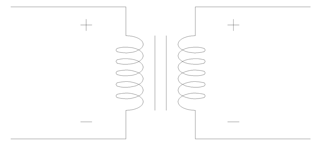
3.1 Additive Polarity
Additive polarity occurs when terminals H1 and X1 are located on the same side of the transformer. If you stand facing the low-voltage side, H1 is on the left and X1 is also on the left. H2 and X2 are both on the right side.
In the polarity test, a jumper wire connects H1 to X1 (since they are on the same side). A voltmeter measures the voltage between H2 and X2. Because H1 and X1 have the same instantaneous polarity and are connected together, the secondary voltage adds to the primary voltage in the measurement loop.
Additive Polarity Formula:
\(V_{Total}=V_{1}+V_{2}\)
Where:
- \(V_1\) = Primary winding voltage
- \(V_2\) = Secondary winding voltage
- \(V_{Total}\) = Voltage measured between opposite terminals
Example: A 230V/115V transformer with additive polarity is tested with 100V applied to the primary. The secondary voltage is 50V (because of the 2:1 turns ratio). The voltage measured between H2 and X2 will be approximately 150V (100V + 50V). This confirms additive polarity.
Per IEEE C57.12.00, additive polarity is standard for single-phase transformers rated 200 kVA and below with high-voltage ratings of 8660V and below.
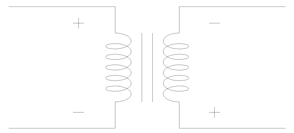
3.2 Subtractive Polarity
Subtractive polarity occurs when terminals H1 and X1 are located on opposite sides of the transformer. If you stand facing the low-voltage side, H1 is on the left but X1 is on the right. H2 is on the right and X2 is on the left. The terminals with the same instantaneous polarity are diagonally opposite to each other.
In the polarity test, a jumper wire connects H1 to X1 (which are on opposite sides, so the jumper crosses over). A voltmeter measures the voltage between H2 and X2. Because of the terminal arrangement, the secondary voltage subtracts from the primary voltage in the measurement loop.
Subtractive Polarity Formula:
\(V_{Total}=V_1−V_2\)
Example: The same 230V/115V transformer with subtractive polarity is tested with 100V on the primary. The secondary voltage is 50V. The voltage between H2 and X2 will be approximately 50V (100V − 50V). This confirms subtractive polarity.
Per IEEE C57.12.00, subtractive polarity is standard for single-phase transformers rated above 200 kVA or with high-voltage ratings above 8660V.
Note: The formula \(V_{Total}=V_1−V_2\) gives the absolute magnitude. A voltmeter reads the magnitude regardless of sign. So for a step-up transformer where \(V_2\) is greater than \(V_1\), the meter will read \(V_2−V_1\), which is simply the absolute value of the difference.
4. Why is the Polarity Test Performed?
4.1 Parallel Operation of Transformers
Connecting two or more transformers in parallel requires that all transformers have the same polarity. If transformers with opposite polarities are connected in parallel, the secondary windings develop voltages that are 180° out of phase. This creates a low-impedance circulating path between the transformer secondaries. A large circulating current flows through both transformers even with no load connected.
This current causes excessive copper losses, rapid overheating, and can destroy the transformers. Protective devices like circuit breakers and fuses may also trip, causing unplanned power outages.
4.2 Three-Phase Bank Connection
Three single-phase transformers are sometimes connected together to form a three-phase bank in delta or wye configurations. Each transformer in the bank must have its polarity correctly identified before connection. If one transformer has its polarity reversed, the three-phase output will have incorrect phase-angle relationships. This causes unbalanced voltages and currents, which can damage motors, drives, and other three-phase equipment connected to the system.
4.3 Protection and Metering Systems
Current transformers (CTs) and potential transformers (PTs) used in protective relaying and metering systems must have correct polarity. If a CT is connected with reversed polarity, the protective relay receives a current signal in the wrong direction. This can cause the relay to not operate during a fault condition or to operate incorrectly during normal conditions.
Energy meters and power factor meters will also give wrong readings if the CT or PT polarity is reversed. This leads to billing errors and incorrect system monitoring.
4.4 Equipment Protection and Personnel Safety
Correct polarity identification prevents accidental short circuits caused by reversed connections. It supports safe parallel operation without excessive currents. It helps maintain design voltage levels throughout the electrical system. It extends transformer lifespan by preventing thermal damage. And it protects personnel from unexpected high currents and equipment failures during commissioning and operation.
5. Polarity Test Procedure for Single Phase Transformer (AC Voltage Method)
5.1 Equipment and Apparatus Required
| Equipment | Specification | Quantity |
|---|---|---|
| Single Phase Transformer | Rated transformer under test | 1 |
| Autotransformer (Variac) | 0-250V AC, rated for test current | 1 |
| Voltmeter 1 (V1) | 0-300V AC, preferably digital | 1 |
| Voltmeter 2 (V2) | 0-300V AC, preferably digital | 1 |
| Voltmeter 3 (V3) | 0-1000V AC or higher if additive polarity expected | 1 |
| Connecting Wires | Properly insulated PVC wires | As required |
| Safety Equipment | Gloves, goggles, mat | 1 set |
5.2 Step-by-Step Test Procedure
Step 1: Initial Preparation and De-energization
Make sure the transformer is completely de-energized and isolated from all power sources. Use a voltage tester to verify that no residual voltage remains on any terminal. Inspect all connecting wires and test equipment for damaged insulation. Verify that all test equipment is properly grounded.
Put on your personal protective equipment including insulated gloves, safety goggles, and stand on a rubber insulating mat.
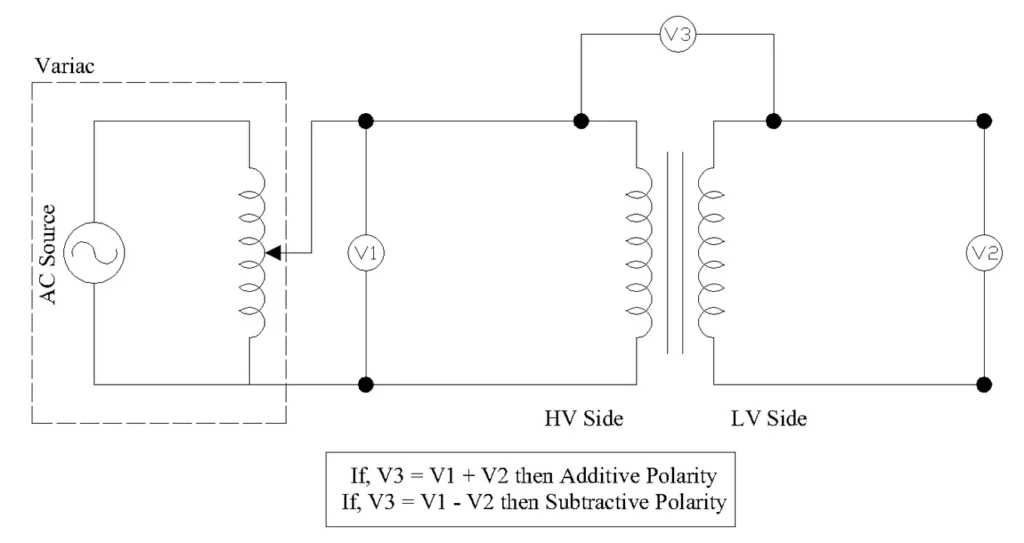
Step 2: Connect the Jumper Wire
Connect a jumper wire between terminal H1 on the primary (high voltage) side and terminal X1 on the secondary (low voltage) side. This jumper creates an electrical connection between one primary terminal and one secondary terminal. This connection is necessary for the test circuit to work. Without this jumper, V3 cannot be measured because the primary and secondary circuits would be electrically isolated from each other.

Step 3: Connect the Voltmeters
Connect Voltmeter V1 across the primary winding terminals H1 and H2. This meter reads the applied primary voltage.
Connect Voltmeter V2 across the secondary winding terminals X1 and X2. This meter reads the induced secondary voltage.
Connect Voltmeter V3 between terminal H2 and terminal X2. This meter reads the test voltage that determines the polarity type.
All three voltmeters are AC voltmeters. AC voltmeters do not have positive and negative terminals — they measure voltage magnitude regardless of probe orientation. Simply connect one probe to each terminal as described.
Step 4: Connect the Autotransformer (Variac)
Connect the autotransformer input to the AC supply (230V, 50Hz or 120V, 60Hz depending on your location). Connect the autotransformer output to the primary winding terminals H1 and H2. Set the autotransformer output to ZERO volts before switching on the supply.
Step 5: Apply Reduced Voltage to the Primary Winding
Switch on the AC supply to the autotransformer. Slowly increase the autotransformer output to apply approximately 50V to 120V to the primary winding. Do NOT apply the full rated voltage.
A reduced voltage is sufficient for this test and protects the transformer insulation. Watch all three voltmeters as you increase the voltage. If anything unusual happens (sparks, smoke, unusual sounds, or rapidly increasing current), immediately reduce the voltage to zero and switch off.
Step 6: Record Voltage Readings
Once the applied voltage is stable, record the readings from all three voltmeters.
- V1 = Voltage across primary winding (H1 to H2)
- V2 = Voltage across secondary winding (X1 to X2)
- V3 = Voltage between H2 and X2
Example readings:
- V1 = 100V
- V2 = 50V
- V3 = ?
Step 7: Determine Polarity Based on V3 Reading
Compare the V3 reading with the calculated values.
If V3 ≈ V1 + V2 (approximately 150V in our example):
The transformer has ADDITIVE POLARITY. Terminals H1 and X1 (which are connected by the jumper) are on the same side of the transformer physically.
If V3 ≈ V1 − V2 (approximately 50V in our example):
The transformer has SUBTRACTIVE POLARITY. Terminals H1 and X1 (which are connected by the jumper) are on opposite sides of the transformer physically.
Allow a tolerance of ±3% in the voltage readings. Small differences are normal due to instrument accuracy, transformer impedance, and supply voltage fluctuations.
Step 8: Mark the Terminal Polarity
After determining the polarity type, mark the transformer terminals using permanent markers, stickers, or engraved labels. Place dot markings (●) on terminals that have the same instantaneous polarity (H1 and X1). Record the results in the transformer test report or commissioning documentation.
Step 9: De-energize and Disconnect
Gradually reduce the autotransformer voltage to zero. Switch off the AC supply. Wait a few moments for any residual energy to dissipate. Disconnect all voltmeters, the jumper wire, and the autotransformer. Remove the transformer from the test setup safely.
6. Alternative Testing Methods
6.1 DC Kick Test Method (Battery Kick Test)
The DC kick test is a quick and simple method to verify winding polarity without applying AC voltage. It is especially useful in the field where an autotransformer or AC supply may not be readily available.
Procedure:
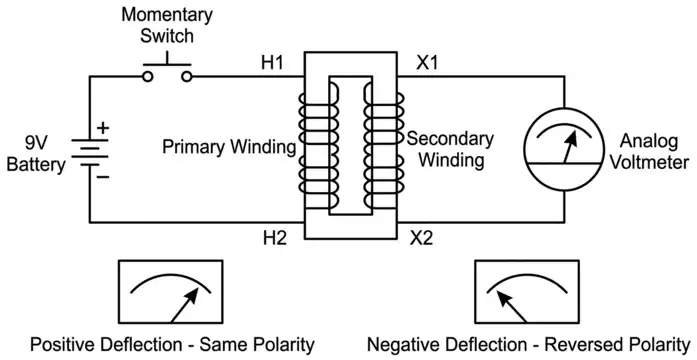
- Connect a low-voltage DC source (a 9V battery works well) to the primary terminals H1 and H2. Connect the positive terminal of the battery to H1 and the negative terminal to H2.
- Connect an analog DC voltmeter (with a center-zero scale if available) to the secondary terminals. Connect the positive probe to X1 and the negative probe to X2.
- Momentarily touch the battery leads to the primary terminals for less than one second. This creates a brief DC pulse (a “kick”) in the primary winding.
- Observe the analog meter needle on the secondary side.
- If the needle deflects in the positive direction (to the right), then H1 and X1 have the same instantaneous polarity. Your polarity assumption is correct.
- If the needle deflects in the negative direction (to the left), then H1 and X1 do NOT have the same polarity. The terminals are reversed from your assumption.
Advantages of the DC Kick Test:
- Quick and simple to perform
- Requires only a battery and an analog meter
- No AC power source needed
- Safe, low-voltage test
- Can be performed on rewound or repaired transformers
Limitations of the DC Kick Test:
- It only confirms or denies the polarity relationship between two specific terminals. It does not directly tell you whether the transformer is additive or subtractive. You need to know the physical terminal positions and combine that information with the test result to determine the polarity type.
- Requires an analog meter. Digital meters respond too slowly to capture the brief pulse.
- Requires practice to reliably interpret the needle deflection, which is very brief.
6.2 Comparison with the AC Voltage Method
The AC voltage method described in Section 5 is the standard and most reliable method. It gives a clear numerical result \((V_{total} = V_1 + V_2\) or \(V_{total} = V_1 − V_2)\) that directly indicates additive or subtractive polarity. The DC kick test is best used as a quick field check or a secondary confirmation. For formal commissioning reports and official test documentation, the AC voltage method is preferred.
7. Observation Table and Documentation
7.1 Standard Observation Table Format
| Serial No. | Primary Voltage (V1) in Volts | Secondary Voltage (V2) in Volts | Test Voltage (V3) in Volts | Polarity Type | Remarks |
|---|---|---|---|---|---|
| 1 | |||||
| 2 | |||||
| 3 | |||||
| Average |
7.2 Calculation and Result Interpretation
After recording readings:
- Calculate Expected Values:
- For additive polarity: \(V3_{expected} = V_1 + V_2\)
- For subtractive polarity: \(V3_{expected} = V_1 – V_2\)
- Compare Measured vs. Expected:
- If measured V3 ≈ (V1 + V2) within ±3% tolerance → ADDITIVE POLARITY
- If measured V3 ≈ (V1 – V2) within ±3% tolerance → SUBTRACTIVE POLARITY
- Record Conclusion:
- Transformer polarity: ____________
- Terminals with same polarity: H1 & X1 (for additive), or H1 & X2 (for subtractive)
- Test conducted by: ____________
- Date and time: ____________
8. Safety Precautions and Best Practices
8.1 Electrical Safety
- De-energize completely: Ensure the transformer is completely disconnected from all power sources before testing
- Use insulated tools: Always use insulated pliers, screwdrivers, and test probes
- Verify zero voltage: Confirm with a voltage tester that no voltage remains before beginning work
- Never touch live terminals: Always keep hands away from exposed energized terminals
- Ground properly: Ensure all test equipment is properly grounded to prevent electrical shock
8.2 Test Voltage Limitations
- Apply reduced voltage: Use 50-120V for test voltage to protect transformer insulation
- Use autotransformer: Employ a step-down autotransformer to safely reduce voltage from the main supply
- Gradual voltage rise: Slowly increase voltage using the autotransformer to observe any abnormalities
- Emergency stop: Have someone ready to quickly de-energize if any abnormality is detected
8.3 Equipment Protection
- Voltmeter range selection: Ensure the voltmeter range is sufficient to measure expected voltages without damage
- Prevent short circuits: Never accidentally short primary and secondary terminals together
- Check winding insulation: Verify that transformer winding insulation is not compromised before testing
- Avoid overheating: Do not conduct extended tests that might overheat the transformer
8.4 Personal Protection Equipment (PPE)
- Safety gloves: Wear insulated rubber gloves rated for the test voltage
- Safety goggles: Protect eyes from potential sparks or dust
- Safety footwear: Use grounded footwear in the laboratory
9. Conclusion
The polarity test of a single phase transformer is a straightforward but important test that every electrical engineer and technician should know how to perform. It determines the instantaneous voltage relationship between primary and secondary windings. This information is needed for safe parallel operation of transformers, correct assembly of three-phase transformer banks, and proper functioning of protection relays and metering systems.
The AC voltage method using an autotransformer and three voltmeters gives a clear and reliable result. The DC kick test provides a quick field verification. Both methods require careful attention to connections, safety precautions, and proper documentation. Transformers should never be connected in parallel or into three-phase banks without first confirming that their polarities are compatible. Taking a few minutes to perform this test can prevent equipment damage, system outages, and safety hazards.
10. Frequently Asked Questions (FAQs)
Additive polarity means that the primary terminal H1 and secondary terminal X1 are located on the same side of the transformer. In the polarity test, the measured voltage V3 equals V1 + V2. Subtractive polarity means that H1 and X1 are on opposite sides of the transformer. The measured voltage V3 equals V1 − V2.
A reduced voltage (50V to 120V) is used for safety and equipment protection. The polarity test only needs to establish the voltage ratio and phase relationship between the primary and secondary windings. Full rated voltage is not necessary for this purpose.
No. The DC kick test produces a very brief voltage pulse on the secondary winding that lasts only a fraction of a second. Digital multimeters have a sampling rate that is too slow to capture this brief pulse.
A large circulating current flows between the two transformer secondaries. This current is not related to the load — it flows even with no load connected. The magnitude of this circulating current is limited only by the internal impedances (winding resistance and leakage reactance) of the two transformers, which are very low. This causes rapid overheating of both transformers, damage to winding insulation, and can lead to transformer failure.
Three-phase transformers have their polarity verified as part of the vector group test rather than a standalone polarity test. The vector group test determines both the polarity and the phase displacement between primary and secondary windings.
The polarity test is performed during initial commissioning of a new transformer and after any rewinding or repair work. It is also done before connecting a transformer in parallel with another transformer or assembling a three-phase bank. The polarity of a transformer does not change during normal operation, so the test does not need to be repeated periodically unless the transformer has been rewound or its internal connections have been modified.
The dot convention is a marking system used in schematic diagrams. A dot is placed at one terminal of each winding to indicate that those terminals have the same instantaneous polarity. If current enters the dotted terminal of the primary winding, the voltage induced at the dotted terminal of the secondary winding has the same polarity.
Yes. If a current transformer or potential transformer is connected with wrong polarity in a metering or protection circuit, the relay or meter receives signals in the wrong direction. An energy meter may register negative power flow or give incorrect kWh readings. A protective relay may fail to operate during a fault or may operate spuriously during normal conditions.