
Leakage flux and leakage reactance are important concepts for understanding the practical behavior of a transformer. An ideal transformer would have perfect magnetic coupling between its primary and secondary windings. In a real transformer, however, a small portion of the magnetic flux produced by each winding does not link the other winding.
This portion is called leakage flux.
The electrical effect associated with leakage flux is represented in the transformer equivalent circuit as leakage reactance. It contributes to the transformer’s internal impedance and therefore affects voltage regulation, load voltage, short-circuit current, and parallel operation.
The basic relationship can be summarized as:
Leakage Flux → Leakage Inductance → Leakage Reactance → Transformer Impedance → Voltage Drop and Fault-Current Limitation
This article explains what leakage flux and leakage reactance are, why they occur, how they are represented mathematically, how they affect transformer performance, and how leakage reactance can be determined from a short-circuit test.
1. Leakage Flux and Leakage Reactance: Quick Answer
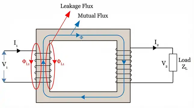
Leakage flux is the portion of the magnetic flux produced by a transformer winding that does not link the other winding.
Leakage reactance is the inductive reactance associated with this leakage flux. It is represented as a series reactance in the practical transformer equivalent circuit.
Mathematically, leakage reactance is expressed as:
\(X_L = 2 \pi f L_L\)
Where:
- \(X_L\) = leakage reactance in ohms (Ω)
- \(f\) = frequency in hertz (Hz)
- \(L_L\) = leakage inductance in henrys (H)
A higher leakage reactance generally causes a greater internal voltage drop under load, but it also limits the current that can flow during a short circuit.
Imagine a simple single-phase transformer with two windings placed on a common iron core. If the primary winding produces 100 units of flux, perhaps 97 units will successfully link with the secondary winding through the core. The remaining 3 units will leak through the air around the primary coil. Those 3 units are the primary leakage flux.
1.1 Leakage Flux vs Mutual Flux
| Feature | Mutual Flux | Leakage Flux |
|---|---|---|
| Links both windings? | Yes | No |
| Main path | Primarily through the magnetic core | Mainly through surrounding air/non-magnetic regions |
| Main effect | Provides magnetic coupling | Produces leakage inductance/reactance |
| Energy transfer between windings | Responsible for coupling | Does not provide useful mutual coupling |
| Location | Common magnetic path | Around individual windings |
2. What Is Leakage Flux in a Transformer?
When an alternating voltage is applied to the primary winding of a transformer, current flows through the winding and establishes magnetic flux.
Ideally, this flux would travel entirely through the transformer core and link both the primary and secondary windings.
In an actual transformer, the magnetic field is distributed through three-dimensional space. Because the windings have finite dimensions and are separated by insulation and other materials, not all of the flux produced by one winding links the other winding.
The portion that links primarily with the winding that produces it is called leakage flux.
There are therefore two commonly considered components:
- Primary leakage flux — associated primarily with the primary winding.
- Secondary leakage flux — associated primarily with the secondary winding.
The exact distribution depends on transformer construction, winding arrangement, physical dimensions, and the magnetic properties of the surrounding materials.
2.1 Why Does Leakage Flux Exist?
Leakage flux exists because magnetic coupling between two real windings cannot be perfectly confined to one common magnetic path.
Factors such as:
- winding separation,
- winding height and width,
- radial and axial dimensions,
- insulation thickness,
- winding arrangement,
- core/window geometry,
influence the amount of leakage flux.
A transformer with tightly coupled windings generally has lower leakage reactance than one with greater magnetic separation between the windings.
3. What Is Leakage Reactance?
Leakage flux produces an associated leakage inductance. When alternating current flows through this inductance, it produces an inductive opposition to current change.
This opposition is represented by leakage reactance.
The fundamental relationship is:
\(X_L = 2 \pi f L_L\)
Therefore, for a given leakage inductance, increasing frequency increases leakage reactance.
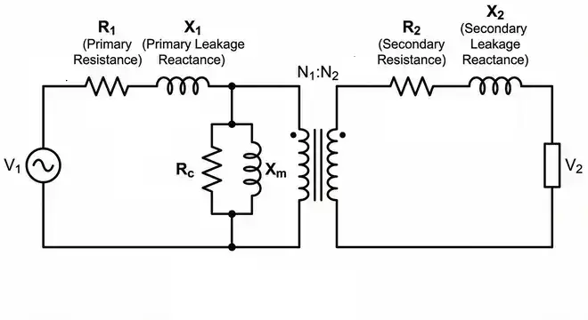
In a transformer equivalent circuit, leakage reactance is represented as a series element.
For example, on the primary side:
\(Z_1=R_1+jX_1\)
where:
- \(R_1\) = primary winding resistance
- \(X_1\) = primary leakage reactance
Similarly, for the secondary:
\(Z_2=R_2+jX_2\)
where:
- \(R_2\) = secondary winding resistance
- \(X_2\) = secondary leakage reactance
The two winding impedances can be referred to the same side of the transformer using the turns ratio.
4. How Leakage Flux Produces Leakage Reactance
The relationship between leakage flux and leakage reactance is easier to understand in three steps.
Step 1: Current produces magnetic flux
Current flowing through a winding produces magnetic flux.
Step 2: Some flux does not link the other winding
Because the windings are physically separated and the magnetic field is not perfectly confined to the core, some flux links only the winding that produces it.
This is leakage flux.
Step 3: Leakage flux produces inductive reactance
The leakage flux is associated with leakage inductance.
That inductance produces an inductive reactance:
\(X_L=2\pi fL_L\)
Therefore:
More leakage inductance → higher leakage reactance.
5. What Causes Leakage Flux in Transformers?
Leakage flux is primarily determined by the physical and electromagnetic design of the transformer.
5.1 Distance Between Windings
Greater physical separation between the primary and secondary windings generally reduces their magnetic coupling and increases leakage flux.
Conversely, bringing the windings closer together generally improves coupling and reduces leakage reactance.
However, transformer design must also provide sufficient insulation and withstand electrical, thermal, and mechanical stresses.
5.2 Winding Arrangement
The arrangement of the primary and secondary windings has a major influence on leakage flux.
For example, winding arrangements that place the windings close together can provide stronger magnetic coupling.
Interleaved winding arrangements can also be used in suitable transformer designs to reduce leakage inductance.
The actual arrangement is selected based on the transformer’s voltage, current, insulation, cooling, mechanical-strength, and impedance requirements.
5.3 Winding Dimensions
The height, radial thickness, number of turns, and physical position of the windings influence the leakage-flux distribution.
Transformer designers use these parameters to achieve the desired impedance rather than simply trying to minimize leakage reactance.
5.4 Insulation and Physical Spacing
Insulation is essential for safe transformer operation. However, the physical space required for insulation between windings contributes to their separation.
Therefore, electrical insulation requirements and leakage reactance must be considered together during transformer design.
5.5 Core and Window Geometry
The dimensions of the transformer core and window affect the magnetic-field distribution around the windings.
A suitable combination of core geometry and winding dimensions helps the designer achieve the required magnetic coupling and impedance.
5.6 Winding Construction
Disc windings, helical windings, layer windings, sandwich windings, and other winding arrangements have different leakage-field distributions.
The choice depends on transformer rating and application.
6. Is Core Saturation the Same as Leakage Flux?
No.
Core saturation and leakage flux are different phenomena and should not be confused.
Leakage flux exists because magnetic coupling between real windings is not perfect.
Core saturation occurs when the magnetic core approaches a region where a relatively large increase in magnetizing force produces only a small increase in flux density.
Saturation can cause:
- excessive magnetizing current,
- waveform distortion,
- increased heating,
- increased noise,
- protection problems.
Therefore, core saturation should not be described as the normal primary cause of transformer leakage flux.
7. Leakage Reactance in the Transformer Equivalent Circuit
A real transformer has winding resistance as well as leakage reactance.
A simplified equivalent circuit therefore contains:
- Primary resistance (R_1)
- Primary leakage reactance (X_1)
- Secondary resistance (R_2)
- Secondary leakage reactance (X_2)
- Magnetizing branch
- Core-loss component
When all series quantities are referred to one side, they can be combined into equivalent resistance and reactance.
The equivalent impedance is:
\(Z_{eq}=R_{eq}+jX_{eq}\)
where:
\(R_{eq}=R_1+R_2’\)
and:
\(X_{eq}=X_1+X_2’\)
The magnitude is:
\(|Z_{eq}|=\sqrt{R_{eq}^2+X_{eq}^2}\)
Transformer impedance contains both resistance and reactance.
For more information about transformer impedance, see Transformer Impedance: Definition, Formula & Examples.
8. Effects of Leakage Reactance on Transformer Performance
Leakage reactance has several important effects on transformer operation.
8.1 Voltage Drop Under Load
When transformer current flows through leakage reactance, a reactive voltage drop occurs.
For a simplified transformer model, the internal voltage drop associated with the series impedance can be represented by:
\(V_{drop}=IZ\)
The exact voltage relationship depends on current magnitude and phase angle.
Therefore, as transformer loading increases, the effect of leakage reactance becomes more significant.
8.2 Voltage Regulation
Leakage reactance is an important contributor to transformer voltage regulation.
For a lagging power-factor load, an approximate expression for voltage regulation is:
\(\%VR\approx \frac{I(R_{eq}\cos\phi+X_{eq}\sin\phi)} {V_{rated}}\times100\)
For a leading power-factor load, the reactive component changes sign:
\(%VR\approx \frac{I(R_{eq}\cos\phi-X_{eq}\sin\phi)} {V_{rated}}\times100\)
Therefore, a higher leakage reactance generally produces greater voltage variation under lagging loads.
For a detailed explanation, see Transformer Voltage Regulation: Formula, Calculation & Examples.
8.3 Limiting Short-Circuit Current
One of the most important practical effects of transformer leakage reactance is that it limits fault current.
During a short circuit, the transformer impedance restricts the current supplied by the transformer.
A simplified relationship is:
\(I_{SC}\approx\frac{V}{Z_{eq}}\)
In per-unit terms, if resistance is neglected for a simplified estimate:
\(I_{SC}\approx\frac{I_{rated}}{Z_{pu}}\)
For percentage impedance:
\(I_{SC}\approx I_{rated}\times\frac{100}{%Z}\)
For example, a transformer with 5% impedance has a theoretical initial symmetrical short-circuit current of approximately:
\(I_{SC}\approx20I_{rated}\)
before considering system impedance and other practical factors.
This is why transformer impedance is an important parameter in fault-current studies and switchgear selection.
For more information, see Short-Circuit Level of a Transformer: Calculation & Examples.
8.4 Effect on Parallel Operation
When transformers operate in parallel, their impedance values and impedance angles influence how they share load.
Transformers intended for parallel operation generally need compatible:
- voltage ratios,
- polarity,
- phase displacement,
- frequency,
- percentage impedance,
- impedance angle.
Significant differences in impedance can result in unequal load sharing.
Therefore, leakage reactance is not just a theoretical parameter; it is relevant to practical transformer-system design.
8.5 Effect on Transformer Fault Stress
Lower transformer impedance allows greater fault current to flow.
Higher impedance restricts fault current but causes greater voltage drop during normal loading.
This creates an important engineering trade-off:
Lower impedance → better voltage regulation but higher fault current
Higher impedance → lower fault current but greater voltage drop
The optimum impedance depends on the transformer’s application and the requirements of the electrical system.
9. Leakage Reactance and Percentage Impedance
Transformer leakage reactance is closely related to transformer percentage impedance.
During a short-circuit test, one winding is short-circuited while a reduced voltage is applied to the other winding.
The voltage required to circulate rated current is called the impedance voltage.
Percentage impedance is:
\(\%Z= \frac{V_{SC}}{V_{rated}}\times100\)
For example, if a transformer has a rated voltage of 11,000 V and rated current is obtained during the short-circuit test when 550 V is applied:
\(\%Z=\frac{550}{11000}\times100\)
\(\%Z=5\%\)
Thus, the transformer has a 5% impedance.
The actual impedance contains both resistance and reactance:
\(Z_{eq}=R_{eq}+jX_{eq}\)
Therefore, percentage impedance should not automatically be treated as exactly equal to percentage leakage reactance.
In many power transformers, the reactive component is larger than the resistance component, but both components should be considered for accurate calculations.
10. How Is Leakage Reactance Calculated?
Leakage reactance can be obtained from the equivalent impedance and equivalent resistance.
First calculate the equivalent impedance:
\(Z_{eq}=\frac{V_{SC}}{I_{SC}}\)
Then calculate equivalent resistance:
\(R_{eq}=\frac{P_{SC}}{I_{SC}^{2}}\)
Finally:
\(X_{eq}=\sqrt{Z_{eq}^{2}-R_{eq}^{2}}\)
where:
- \(V_{SC}\) = short-circuit test voltage
- \(I_{SC}\) = short-circuit test current
- \(P_{SC}\) = short-circuit test power
- \(Z_{eq}\) = equivalent impedance
- \(R_{eq}\) = equivalent resistance
- \(X_{eq}\) = equivalent reactance
The calculated reactance represents the transformer’s equivalent series reactance referred to the side on which the measurements are made.
11. Worked Example: Calculate Transformer Leakage Reactance
Consider the following short-circuit test results:
- Short-circuit voltage = 187 V
- Short-circuit current = 10.4 A
- Short-circuit power = 750 W
Step 1: Calculate Equivalent Impedance
\(Z_{eq}=\frac{V_{SC}}{I_{SC}}\)
\(Z_{eq}=\frac{187}{10.4}\)
\(Z_{eq}\approx17.98\Omega\)
Step 2: Calculate Equivalent Resistance
\(R_{eq}=\frac{P_{SC}}{I_{SC}^{2}}\)
\(R_{eq}=\frac{750}{(10.4)^2}\)
\(R_{eq}\approx6.93\Omega\)
Step 3: Calculate Equivalent Reactance
\(X_{eq}=\sqrt{Z_{eq}^{2}-R_{eq}^{2}}\)
\(X_{eq}=\sqrt{17.98^2-6.93^2}\)
\(X_{eq}\approx16.59\Omega\)
Therefore:
\(\boxed{X_{eq}\approx16.59\Omega}\)
The equivalent reactance referred to the test side is approximately 16.59 Ω.
This value can then be used in transformer equivalent-circuit, voltage-regulation, and fault-current calculations.
For a complete explanation of the test itself, see Short-Circuit Test of a Transformer.
12. How Is Leakage Reactance Measured?
The most common practical method for determining transformer series impedance is the short-circuit test.
The basic procedure is:
- Short-circuit one transformer winding.
- Apply a low AC voltage to the other winding.
- Increase the applied voltage gradually.
- Stop when the specified test current, commonly rated current, is reached.
- Record voltage, current, and power.
- Calculate (Z_{eq}), (R_{eq}), and (X_{eq}).
The applied voltage is only a fraction of the transformer’s rated voltage, so the core flux during the test is low and core loss is comparatively small.
The test provides valuable information about:
- equivalent impedance,
- equivalent resistance,
- equivalent reactance,
- copper/load losses,
- percentage impedance.
13. Is Leakage Reactance Always Undesirable?
No.
It is tempting to assume that transformer designers should always minimize leakage reactance. However, transformer impedance is deliberately controlled according to the application.
Leakage reactance has an undesirable effect because it contributes to voltage drop and can worsen voltage regulation.
At the same time, it provides an important benefit:
It limits short-circuit current.
Consider two simplified transformers:
| Transformer | Percentage Impedance | Approx. Fault Current |
| Transformer A | 5% | 20 × rated current |
| Transformer B | 10% | 10 × rated current |
These are simplified calculations assuming transformer impedance is the dominant limiting impedance.
Therefore, transformer designers must balance:
- voltage regulation,
- fault-current limitation,
- thermal performance,
- mechanical short-circuit strength,
- parallel-operation requirements,
- system fault levels.
The objective is not necessarily the lowest possible leakage reactance. The objective is the appropriate impedance for the intended application.
14. How Do Transformer Designers Control Leakage Reactance?
Leakage reactance is controlled primarily through transformer geometry and winding construction.
Some design approaches include:
14.1 Reducing Winding Separation
Closer windings generally improve magnetic coupling and reduce leakage reactance, provided insulation requirements can still be satisfied.
14.2 Optimizing Winding Arrangement
Appropriate concentric, sandwich, disc, helical, or interleaved arrangements can be selected according to the required impedance.
14.3 Interleaving Windings
In suitable transformer designs, interleaving sections of primary and secondary windings can improve coupling and reduce leakage inductance.
14.4 Optimizing Winding Dimensions
Winding height, radial dimensions, and relative positioning influence leakage-field distribution.
14.5 Designing for a Required Impedance
The final transformer design must achieve the required impedance rather than simply minimizing leakage.
This is particularly important in power transformers where the specified impedance is part of the overall system design.
15. Leakage Reactance vs Magnetizing Reactance
These two terms are sometimes confused because both are represented as reactances in a transformer equivalent circuit.
| Feature | Leakage Reactance | Magnetizing Reactance |
| Associated flux | Leakage flux | Main/mutual flux |
| Circuit location | Series branch | Shunt/magnetizing branch |
| Main purpose | Represents imperfect winding coupling | Represents current required to establish core flux |
| Effect | Load-dependent voltage drop | Determines magnetizing current |
| Importance during short-circuit test | Significant | Much less important because applied voltage is low |
A simple way to remember the difference is:
Leakage reactance is a series effect.
Magnetizing reactance is a shunt effect.
16. Can Leakage Reactance Be Zero?
In a real transformer, leakage reactance cannot realistically be reduced to exactly zero.
Perfect magnetic coupling would require all flux produced by one winding to link the other winding.
Real transformers have:
- finite winding dimensions,
- insulation,
- physical spacing,
- leakage fields,
- three-dimensional magnetic-field distributions.
Therefore, some leakage inductance and leakage reactance remain.
The engineering objective is to design the transformer with an appropriate value rather than attempting to eliminate leakage reactance completely.
17. Key Takeaways
The most important points to remember are:
- Leakage flux is the portion of transformer flux that does not link both windings.
- Leakage flux produces leakage inductance.
- Leakage inductance produces leakage reactance.
- Leakage reactance is given by:
\(X_L=2\pi fL_L\)
- Leakage reactance forms part of the transformer’s series impedance.
- Higher leakage reactance generally causes greater voltage drop under load.
- Transformer impedance limits short-circuit current.
- Leakage reactance is not the same as total transformer impedance.
- Leakage reactance can be determined from short-circuit test data.
- Transformer designers control leakage reactance according to the required balance between voltage regulation and fault-current limitation.
18. Conclusion
Leakage flux is an unavoidable consequence of the finite geometry and imperfect magnetic coupling of real transformer windings. The portion of flux that does not link both windings produces leakage inductance, which appears electrically as leakage reactance.
The resulting leakage reactance is an important component of transformer impedance. It contributes to load-dependent voltage drop and voltage regulation, while also limiting short-circuit current during faults.
The key relationship is:
\(\boxed{\text{Leakage Flux}\rightarrow\text{Leakage Inductance}\rightarrow\text{Leakage Reactance}}\)
Understanding this relationship makes it easier to understand several other transformer concepts, including transformer impedance, voltage regulation, short-circuit testing, percentage impedance, and fault-current calculations.
For further study, explore the related Wiringuru guides on Transformer Impedance, Transformer Voltage Regulation, Transformer Short-Circuit Test, and Transformer Short-Circuit Level.
12. Frequently Asked Questions (FAQs)
Leakage flux is the portion of magnetic flux produced by a winding that does not link with the other winding. It completes its path through the air or non-magnetic material instead of traveling through the iron core.
Leakage flux is caused by the physical separation between windings, air gaps in the magnetic circuit, core saturation, and the geometry of the winding arrangement.
Leakage reactance causes a voltage drop inside the transformer that increases with load current. A higher leakage reactance results in poorer voltage regulation because the output voltage drops more from no-load to full-load conditions.
No, leakage flux can never be completely eliminated in a practical machine. It can only be minimized through better winding design, closer winding spacing, and optimized core geometry.
Leakage reactance is due to the leakage flux that links with only one winding. Magnetizing reactance is due to the mutual flux that flows through the core and links both windings. Magnetizing reactance represents the current needed to establish the core flux.
Leakage reactance is measured using the short-circuit test. The secondary winding is short-circuited, a reduced voltage is applied to the primary, and the impedance is calculated. The reactive component of this impedance is the leakage reactance.
Higher leakage reactance reduces the starting torque of an induction motor. The starting torque is inversely proportional to the total leakage reactance of the motor circuit.
Yes. Leakage reactance is directly proportional to frequency (X_L = 2πfL_L). A transformer operating at 60 Hz will have a higher leakage reactance than the same transformer operating at 50 Hz, assuming the leakage inductance remains constant.