
Transformer core saturation is one of those topics that every electrical engineer should understand clearly. It affects the performance of power transformers, distribution systems, and electronic circuits in ways that can lead to serious operational problems.
Transformer core saturation happens when the magnetic material inside a transformer cannot carry any more magnetic flux. The core loses its ability to respond to increases in the applied magnetic field. This leads to a sharp drop in inductance, a rise in magnetizing current, and a range of problems like heat, noise, and distortion.
In this technical guide, we will discuss everything you need to know about transformer core saturation, including its working principle, types, causes, effects, practical examples, calculation methods, and prevention strategies. Practical examples are included throughout to help you apply these concepts in real-world scenarios confidently.
1. What Is a Transformer Core and Why Does It Matter?
Before getting into saturation, it helps to understand the role of the transformer core itself.
A transformer core is the magnetic structure that links the primary winding to the secondary winding. It is made from magnetic materials like silicon steel, ferrite, or amorphous metal. The core provides a low-reluctance path for the magnetic flux to travel between windings.
Without the core, most of the magnetic flux produced by the primary winding would scatter into the surrounding air. Very little flux would link with the secondary winding, and the transformer would be highly inefficient. The core keeps the flux confined and channeled from one winding to the other.
The core has a property called permeability. High permeability means the material allows magnetic flux to pass through it easily. This is a good quality in a transformer core because it means you need less magnetizing current to set up the required flux.
However, every magnetic material has a limit to how much flux it can carry. Once you push beyond that limit, the material reaches saturation. That is exactly where the problem begins.
2. The Basic Concept of Magnetic Flux and the B-H Curve
To understand saturation properly, you need to know about the B-H curve, also called the magnetization curve.
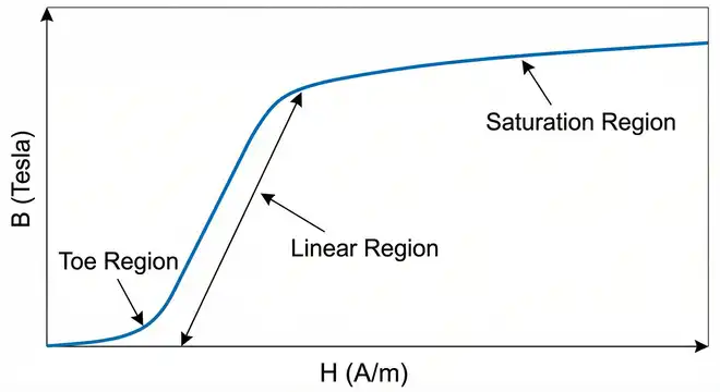
In magnetic materials, B refers to the magnetic flux density measured in Tesla (T). It tells you how much magnetic flux is passing through a unit area of the core.
H refers to the magnetic field intensity measured in Ampere-turns per meter (A/m). It tells you how much magnetizing force is being applied to the core. H is directly related to the current flowing through the primary winding.
When you plot B on the vertical axis and H on the horizontal axis, you get the B-H curve. This curve tells the whole story of how a magnetic material responds to an increasing magnetizing force.
In the early part of the curve, B increases nearly in proportion to H. The relationship is almost linear. This is the normal operating region for a well-designed transformer.
As H continues to increase, B starts to rise more slowly. The curve begins to bend. The core is approaching its magnetic limit.
Eventually, the curve becomes nearly flat. Even if you continue to increase H significantly, B barely changes. The material has reached saturation. All the magnetic domains inside the material are already aligned. There is no more room for additional flux.
The point at which the curve starts to flatten noticeably is called the saturation point. For silicon steel used in power transformers, this is around 1.5 to 2.0 Tesla.
A practical way to think about this is to imagine filling a sponge with water. At first, the sponge absorbs water easily. Then it starts to slow down. At some point, you can keep pouring water but the sponge simply cannot absorb any more. The core behaves in a similar way with magnetic flux.
3. What Exactly is Transformer Core Saturation?
Transformer core saturation is the condition where the magnetic core of a transformer reaches its maximum magnetic flux density. Beyond this point, the core material cannot support any further increase in flux, even if the applied voltage or current continues to rise.
In normal operation, the primary voltage drives a small magnetizing current through the primary winding. This magnetizing current sets up a magnetic flux in the core. The flux then induces a voltage in the secondary winding. The ratio of primary to secondary voltage matches the turns ratio of the transformer.
The magnetizing current is normally very small, usually around 1% to 5% of full-load current for a well-designed power transformer. The core operates in the linear region of the B-H curve where permeability is high.
Once the core saturates, the effective permeability of the core drops sharply. Permeability is the ratio of B to H. In the saturated region, B barely changes while H increases rapidly. So the ratio B/H falls dramatically.
Lower permeability means the inductance of the primary winding falls sharply. Lower inductance means the winding offers very little opposition to changes in current. The magnetizing current then rises to very high levels, almost like the primary winding is short-circuited.
This sudden spike in magnetizing current is a clear sign of saturation. It can be many times the normal operating current. This large current causes excessive heating of the windings, additional losses in the core, voltage distortion, and mechanical stress on the windings.
4. How the Magnetizing Current Changes During Saturation
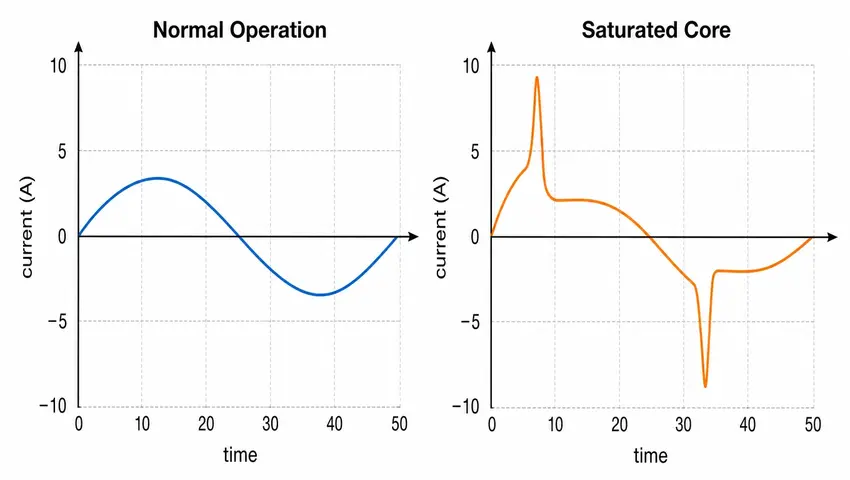
One of the most visible signs of transformer saturation is the change in the shape of the magnetizing current waveform.
In normal operation, if the applied voltage is sinusoidal, the flux in the core is also roughly sinusoidal. The magnetizing current is relatively small and smooth.
Once the core saturates, the situation changes. The flux still tries to follow the sinusoidal pattern because it is driven by a sinusoidal voltage. But each time the flux reaches the peak of the sine wave, the core saturates briefly at the top and bottom of each cycle.
At these moments, the magnetizing current spikes sharply to very high values. The waveform of the magnetizing current is no longer smooth. It becomes heavily distorted and peaky. Engineers describe this as a “peaky” or “spiky” magnetizing current waveform.
This distorted current contains odd harmonics, especially the third harmonic and fifth harmonic. These harmonics can cause problems in connected equipment, create interference in communication circuits, and affect protection relays in substation applications.
5. Common Causes of Transformer Core Saturation
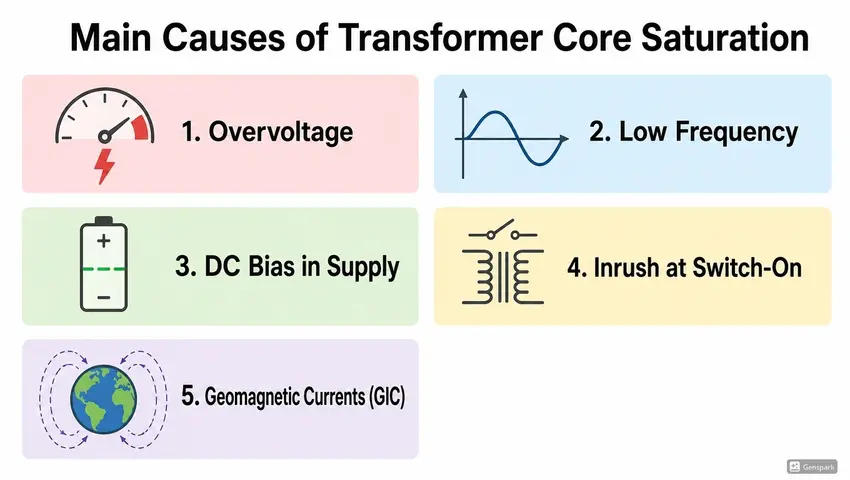
Several conditions can push a transformer core into saturation. Let us look at each one clearly.
5.1 Overvoltage
The most common cause of saturation is overvoltage. The flux in a transformer core is directly proportional to the applied voltage and inversely proportional to the frequency and number of turns.
The formula is:
\(\Phi_{max}=\dfrac{V}{4.44\times f\times N}\)
Where:
- \(\Phi_{max}\) = peak flux
- \(V\) = applied RMS voltage
- \(f\) = frequency in Hz
- \(N\) = number of turns
If the voltage rises above the design level, the flux increases. If the flux exceeds the saturation flux density of the core material, saturation occurs.
5.2 Low Frequency Operation
Looking at the same formula, if the frequency drops while voltage stays the same, the flux must increase. This can happen if a transformer rated for 60 Hz is operated at 50 Hz. The flux would increase by 60/50 = 1.2 times, which is a 20% increase. This may be enough to saturate the core.
5.3 DC Bias or DC Offset in the Supply
A transformer core is designed to handle alternating magnetic flux. The flux swings symmetrically between positive and negative peaks during each cycle.
If a DC component appears in the supply voltage, it adds a constant unidirectional bias to the flux. The flux no longer swings symmetrically. It shifts toward one side of the B-H curve.
This means the positive peak of flux is pushed much higher than the negative peak. The positive peak may enter the saturation region even though the applied AC voltage is within normal limits.
DC offset in transformer supplies can come from half-wave rectifier loads, geomagnetically induced currents (GIC) during solar storms, or neutral current imbalance in three-phase systems.
5.4 Geomagnetically Induced Currents (GIC)
This is a real-world problem for high-voltage transmission transformers. During solar storms, the earth’s magnetic field changes rapidly. This induces quasi-DC currents in long transmission lines and through transformer windings.
These DC currents are small in magnitude but they cause severe half-cycle saturation in large power transformers. The magnetizing current distortion from GIC events has caused transformer failures and widespread blackouts.
The Quebec blackout of March 1989 is a well-documented example. A severe geomagnetic storm induced currents in the Hydro-Québec transmission system, saturated transformers, and eventually caused a complete system collapse affecting millions of people.
5.5 Inrush Phenomenon at Switch-On
Every time a transformer is energized, there is a transient period called the inrush period. The residual flux remaining in the core from the previous de-energization, combined with the new flux built up by the applied voltage, can together exceed the saturation flux density.
This happens because the flux starts to build from the residual value rather than from zero. If the transformer is switched on at an unfavorable point of the voltage waveform, the flux can reach nearly twice its normal peak value.
This causes a large inrush current that can be 8 to 12 times the full-load current. The inrush current decays over a few seconds as the core flux settles into its steady-state pattern.
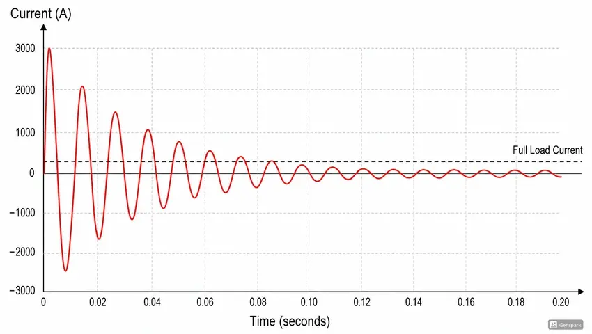
Inrush saturation is temporary and is not a fault condition. But protection relays must be set carefully to avoid tripping the transformer during inrush. Differential protection relays use harmonic restraint to distinguish between inrush currents and actual fault currents.
5.6 Core Geometry and Material Limitations
If a transformer is poorly designed with insufficient core cross-section area, the core may reach saturation even at rated voltage and frequency. This is a design error that should be caught during the design stage.
Similarly, if the wrong core material is selected for the application, the saturation flux density may be too low for the required operating flux density.
6. Effects of Transformer Core Saturation
Saturation causes a range of problems that can affect both the transformer itself and the wider electrical system. Let us go through the main effects.
6.1 Excessive Magnetizing Current
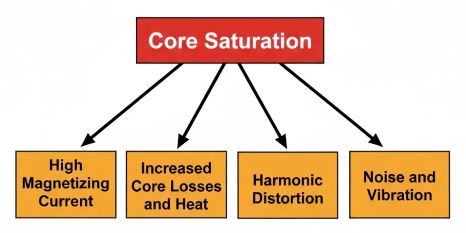
As discussed earlier, saturation causes the magnetizing current to spike. This large current flows through the primary winding even with no load connected. The winding heats up. The insulation deteriorates over time.
6.2 Increased Core Losses
In the saturated region, the core undergoes rapid changes in its magnetic domain structure during each cycle. This increases both hysteresis losses and eddy current losses in the core. The core temperature rises.
For large power transformers, this additional heat can overwhelm the cooling system. Oil temperature rises. The transformer may operate above its rated temperature, which accelerates insulation aging. The general rule is that every 10°C rise above the rated temperature halves the insulation life of the transformer.
6.3 Harmonic Generation
Saturation causes the magnetizing current to contain large amounts of harmonic frequencies. The third harmonic is usually the largest. In three-phase systems, third harmonics are zero-sequence quantities and can cause problems with neutral conductors and grounding systems.
These harmonics also cause voltage distortion, which can affect other equipment connected to the same bus. Sensitive electronic equipment, variable frequency drives, and power quality meters may all be affected.
6.4 Noise and Vibration
A saturated core produces more magnetostrictive force than a non-saturated core. Magnetostriction is the slight change in the physical dimensions of the magnetic material as it magnetizes. When this happens at twice the supply frequency and with harmonics present, it generates audible noise and mechanical vibration.
A transformer going into saturation will produce a noticeable hum or buzzing sound that is louder and higher-pitched than its normal operating noise.
6.5 Relay Maloperation
Current transformers (CTs) used in protection systems can themselves saturate. When a high fault current flows through the primary circuit, the CT core may saturate before the secondary current signal accurately represents the primary current. This can cause protection relays to measure incorrect values and either fail to operate or operate incorrectly.
In differential protection schemes, CT saturation during external faults can cause the relay to see a false differential current and trip the protected transformer unnecessarily.
7. Transformer Saturation in Practical Systems
Let us look at some practical scenarios to make these concepts more concrete.
7.1 Scenario 1: Distribution Transformer in a Rural Feeder
A 11 kV/415 V, 100 kVA distribution transformer is connected at the end of a long rural feeder. During light load conditions at night, the feeder voltage rises to 12.5 kV due to the Ferranti effect and poor voltage regulation.
The transformer was designed for a maximum flux density of 1.7 T at 11 kV. At 12.5 kV, the flux density rises to approximately 1.7 × (12.5/11) = 1.93 T. This exceeds the saturation level of the core material.
The transformer draws a large magnetizing current, heats up, and produces audible noise. If this condition persists regularly, the insulation will degrade and the transformer will fail prematurely.
The solution here is to either adjust the tap changer to reduce the secondary voltage, install voltage regulation equipment, or ensure proper reactive power compensation along the feeder.
7.2 Scenario 2: Power Supply Transformer in an Industrial Drive
A 480 V/120 V isolation transformer feeds the control electronics of an industrial motor drive. The plant adds a large rectifier load on the same bus. The rectifier draws non-sinusoidal current and causes voltage distortion.
The distorted voltage contains a DC offset that persists for periods. This DC offset causes the flux in the isolation transformer to drift toward saturation. The transformer overheats, and the control electronics experience unstable supply voltage.
The fix involves adding a line reactor or an active filter to eliminate the DC component from the supply.
8. How to Calculate the Saturation Point
Engineers need to calculate whether a transformer core will saturate under specific conditions. Here is a straightforward approach.
The peak flux density in a transformer core is given by:
\(B_{max} = \dfrac{V_{rms}}{4.44\times f\times N\times A_c}\)
Where:
- \(B_{max}\) = peak flux density in Tesla
- \(V_{rms}\) = applied RMS voltage in Volts
- \(f\) = supply frequency in Hz
- \(N\) = number of turns in the winding
- \(A_c\) = cross-sectional area of the core in square meters
To avoid saturation, \(B_{max}\) must remain below the saturation flux density of the core material \((B_{sat})\).
For silicon steel, \(B_{sat}\) is approximately 1.5 to 2.0 Tesla depending on the specific grade.
8.1 Example Calculation:
A single-phase transformer has:
- Primary turns N = 500
- Core area A_c = 0.002 m²
- Supply frequency f = 50 Hz
- Rated voltage V = 230 V
\(B_{max} = \dfrac{230}{4.44 \times 50 \times 500 \times 0.002}\)
\(B_{max} = \dfrac{230}{222}\)
\(B_{max} \approx 1.04 \text{ Tesla}\)
This is safely below the saturation level of silicon steel. The transformer has a comfortable margin.
Now if the voltage rises to 280 V:
\(B_{max} = \dfrac{280}{222} \approx 1.26 \text{ Tesla}\)
Still safe, but the margin is smaller.
If the voltage rises to 350 V:
\(B_{max} = \dfrac{350}{222} \approx 1.58 \text{ Tesla}\)
This is approaching the saturation region. The core may begin to saturate.
9. How to Prevent Transformer Core Saturation
Prevention is far better than dealing with the consequences of saturation. Here are the main strategies engineers use.
9.1 Proper Voltage Regulation
Maintaining the supply voltage within the rated limits is the most direct way to prevent overvoltage-induced saturation. Voltage regulators, automatic voltage stabilizers, and on-load tap changers (OLTCs) all help achieve this.
9.2 Conservative Core Design
Designing the transformer with a lower operating flux density gives a larger margin before the saturation point is reached. Many designers target a flux density of around 1.5 to 1.7 Tesla for 50/60 Hz power transformers using grain-oriented silicon steel, which has a saturation level of about 2.0 Tesla.
This leaves adequate headroom for overvoltage events without driving the core into saturation immediately.
9.3 Using Core Materials with Higher Saturation Flux Density
Some special iron-cobalt alloys like Permendur can achieve saturation flux densities of up to 2.4 Tesla. Using such materials allows the transformer to handle higher flux levels without saturating.
However, these materials are expensive. They are mainly used in aerospace and military applications where size and weight are more important than cost.
9.4 DC Blocking Techniques
To prevent DC bias from entering the transformer, engineers use series capacitors, DC blocking circuits, or active compensation devices. These are especially important for transformers feeding rectifier loads or systems prone to GIC events.
9.5 Pre-fluxing at Controlled Energization
Some modern transformer switching systems control the point on the voltage waveform at which the transformer is energized. By switching the transformer in at the correct phase angle, residual flux and initial flux can add constructively without pushing the core into saturation. This reduces inrush current significantly.
This technique is called controlled switching or point-on-wave switching. It is used on large generator transformers and important transmission transformers.
9.6 Protection Relay Settings
Overvoltage protection relays (V/Hz relays or volts-per-hertz relays) monitor the ratio of voltage to frequency. If this ratio exceeds a set threshold, the relay trips the transformer. This is especially important in generator step-up transformers where both voltage and frequency can vary during startup and shutdown.
10. Saturation in Current Transformers vs. Power Transformers
It is worth noting that saturation affects current transformers (CTs) differently from power transformers.
A power transformer saturates mainly due to excessive applied voltage or DC bias. A CT saturates mainly due to excessive primary current or a high burden on the secondary side.
When a CT saturates, the secondary current waveform becomes distorted and no longer accurately represents the primary current. This is a serious problem for protection relays that depend on accurate current measurement.
CT saturation standards are covered in IEC 61869 and IEEE C57.13. Engineers select CTs with a sufficient accuracy limit factor (ALF) or C class voltage rating to ensure they do not saturate during fault conditions.
11. Conclusion
Transformer core saturation is a real and well-defined phenomenon that engineers encounter across power generation, transmission, distribution, and electronics. It occurs when the magnetic core reaches its maximum flux capacity and can no longer respond linearly to the applied magnetizing force.
The consequences range from excessive magnetizing current and increased losses to harmonic distortion and protection relay problems. In large power systems, saturation events can contribute to equipment damage and even system-wide failures as seen in documented geomagnetic storm events.
12. Frequently Asked Questions (FAQs)
Transformer core saturation is the condition where the magnetic material inside a transformer can no longer carry more magnetic flux. When this happens, the inductance of the winding drops sharply and the magnetizing current rises to very high values, causing heat, noise, and distortion.
The main causes are overvoltage, low supply frequency, DC bias in the supply current, residual flux at energization (inrush), and geomagnetically induced currents.
Signs include excessive heating with no load, audible buzzing or humming louder than normal, distorted or spiky current waveforms on the primary side, and high harmonic distortion levels measured with a power quality analyzer.
Inrush current is caused by temporary saturation of the core at the moment the transformer is switched on. It is a transient condition that lasts for a few seconds and then disappears.
If the transformer has been operating in saturation for a long time, the insulation may be damaged. In that case, rewinding or replacement may be needed. If saturation was brief, removing the cause (reducing voltage, eliminating DC bias) may restore normal operation without permanent damage.