
A PN junction diode can be tested using a multimeter in two ways using the diode test mode or the resistance (ohmmeter) mode. Both the methods checks whether the diode conducts in forward direction and blocks in the reverse direction.
A good diode will show a low voltage drop (or low resistance) in forward direction and a very high or infinite resistance in reverse direction.
1. What You Need Before Starting?
Only a digital multimeter and the diode that is to be tested is needed for conducting the test. The diode must be removed from the circuit before testing. Testing a diode while it is still connected to a circuit gives inaccurate readings because other components in the circuit interfere with the measurement.
Also identify the diode terminals. The anode is the positive terminal and the cathode is the negative terminal. Most diodes have a silver or white band printed on the cathode end of the body as shown in the figure below.

2. Method 1: Using the Diode Test Mode
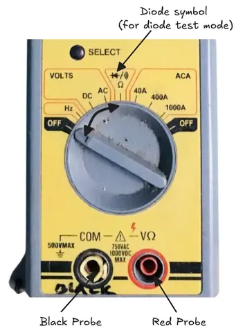
Modern digital multimeters has a dedicated diode symbol on the selector dial. It looks like a triangle pointing into a vertical line. This mode is the most accurate way to test a diode.
Step 1: Set the Multimeter
Rotate the selector dial to the diode test symbol. Plug the red probe into the VΩ port and the black probe into the COM port.
Step 2: Forward Bias Test
Touch the red probe to the anode and the black probe to the cathode to connect the diode in forward bias. A good silicon diode should show a voltage drop reading between 0.5V and 0.8V on the display and a good germanium diode shows voltage drop between 0.2V and 0.3V.
This reading confirms that the diode is conducting properly in the forward direction.
Step 3: Reverse Bias Test
Now swap the probes. Touch the red probe to the cathode and the black probe to the anode to put the diode in reverse bias mode. A healthy diode will show OL (overload) or 1 on the display. This means that the resistance is too high to measure and the diode is blocking current in the reverse direction as it should.
Step 4: Read the Results
| Condition | Forward Bias Reading | Reverse Bias Reading | Verdict |
|---|---|---|---|
| Good Diode | 0.5V – 0.8V (Silicon) | OL or 1 | Diode is working |
| Shorted Diode | 0V or near 0V | 0V or near 0V | Diode is shorted |
| Open Diode | OL or 1 | OL or 1 | Diode is open |
3. Method 2: Using the Ohmmeter or Resistance Mode
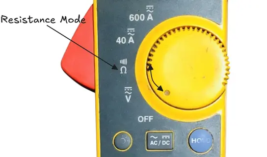
If the multimeter does not have a diode test mode, you can use the resistance mode.
Forward Bias Test
Set the multimeter to the low resistance range.
Connect the red probe to the anode and the black probe to the cathode. A healthy diode will show a low resistance value in between fraction of an ohm to a few hundred ohms.
Reverse Bias Test
Set the multimeter to the high resistance range.
Swap the probes to connect the red probe to the cathode and black probe to the anode. The multimeter should show a very high resistance or infinite resistance (OL). This confirms the diode is blocking reverse current.
Note: The ohmmeter method is less accurate than the diode test mode. The exact resistance value varies between different multimeters because each meter uses a different internal voltage for the ohmmeter function. Use the diode test mode whenever possible
4. Summary
Testing a PN junction diode with a multimeter is very simple. The diode test mode in modern multimeters gives the most accurate results. A healthy diode shows a forward voltage drop between 0.5V and 0.8V (for silicon) and OL in reverse. Any deviation in both readings being 0V or both showing OL means the diode has failed.
This test takes less than a minute and saves time during circuit troubleshooting.
5. Frequently Asked Questions (FAQs)
A silicon diode shows a forward voltage drop between 0.5V and 0.8V. The most common reading for a standard rectifier diode like 1N4007 is around 0.6V to 0.7V.
No. Other components connected in parallel with the diode will affect the reading.
It means the diode is open and the internal PN junction is broken. The diode is not conducting at all and needs to be replaced.
No. A reading of 0.00V in both directions means the diode is shorted. The junction has failed and current flows freely in both directions. Replace the diode.
Yes. Set the analog multimeter to the low resistance range (Rx1 or Rx10). In forward bias, the needle should deflect to the right showing low resistance. In reverse bias, the needle should barely move, showing high resistance.