The vector group test is one of the most important pre-commissioning tests performed on three-phase transformers. This test verifies the phase relationships and angular displacement between the high voltage (HV) and low voltage (LV) windings of a transformer. Before a transformer is energized or connected in parallel with other transformers, engineers must confirm that the winding connections and phase shifts match the nameplate specifications. A wrong vector group connection can lead to large circulating currents, transformer overheating, insulation damage, and even complete transformer failure.
Every electrical engineer working in transformer testing, commissioning, and power system maintenance should have a solid grasp of vector group testing. The test is straightforward in concept but requires careful attention to terminal connections, voltage measurements, and interpretation of results. Mistakes during this test can have serious consequences for both equipment and personnel safety.
In this technical guide, we will discuss everything you need to know about the vector group test of transformers, including its working principle, vector group notation, detailed test procedures for all common vector groups, test conditions, measurement techniques, and parallel operation requirements. Practical examples are included throughout to help you apply these concepts in real-world scenarios confidently.
1. What is a Vector Group of a Transformer?
A vector group is the IEC standardized method of describing the winding configuration of a three-phase transformer and the phase angle difference between its HV and LV windings. The International Electrotechnical Commission (IEC) developed this classification system under the IEC 60076-1 standard to provide a universal language for transformer winding arrangements.
The vector group designation tells us three things. First, it describes how the HV winding is connected — whether in Delta, Star, or Zigzag configuration. Second, it describes the LV winding connection type. Third, it indicates the phase displacement between the HV and LV windings expressed as a multiple of 30 degrees.
In the notation system, uppercase letters represent the HV winding and lowercase letters represent the LV winding. The letter “D” or “d” stands for Delta connection. The letter “Y” or “y” stands for Star connection. The letter “Z” or “z” stands for Zigzag connection. The letter “N” or “n” indicates that the neutral point is brought out and accessible.
For example, consider the vector group designation Dyn11. Here, “D” means the HV winding is connected in Delta. The lowercase “y” means the LV winding is connected in Star. The “n” means the LV neutral is brought out. The number “11” indicates the phase displacement using clock notation, which we will discuss next.
2. Clock Notation for Vector Groups
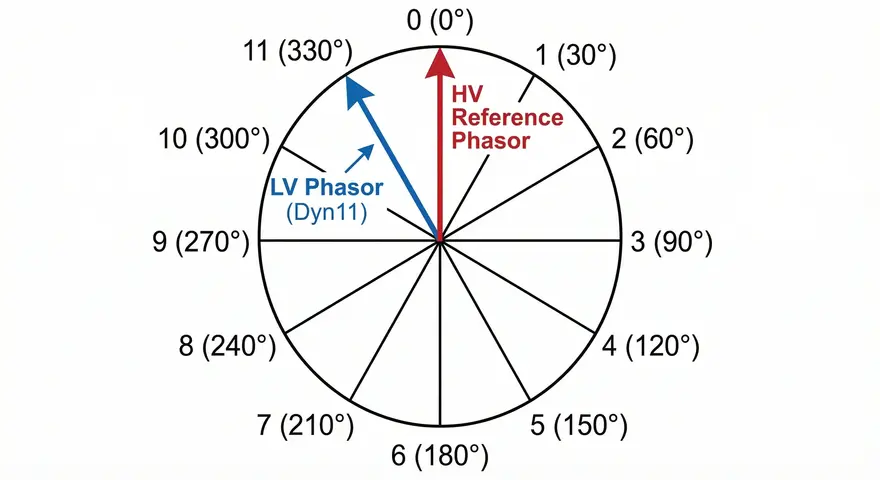
The IEC uses a clock notation system to express the phase displacement between HV and LV windings. This is an elegant and easy-to-remember system that works as follows.
Imagine a clock face. The HV winding phasor is always fixed at the 12 o’clock position. This is the reference phasor that does not move. The LV winding phasor points to a position on the clock face that indicates its phase displacement relative to the HV winding. Each hour on the clock represents 30 degrees of phase shift. The phasor rotation follows the counterclockwise direction.
Let us look at some examples to make this clear.
Clock position 0 (12 o’clock): The LV phasor is at 12 o’clock, meaning 0° phase displacement. The HV and LV windings are in phase. Examples include Yy0 and Dd0.
Clock position 6: The LV phasor is at 6 o’clock, meaning 180° phase displacement. The LV winding is completely out of phase with the HV winding. Examples include Yy6 and Dd6.
Clock position 1: The LV phasor is at 1 o’clock, meaning the LV lags the HV by 30°. Examples include Yd1 and Dy1.
Clock position 11: The LV phasor is at 11 o’clock, meaning the LV leads the HV by 30°. Examples include Yd11 and Dy11.
This clock notation makes it very easy to visualize the phase relationship. If someone tells you a transformer has a Dyn11 vector group, you immediately know that the LV side leads the HV side by 30 degrees.
3. Why is Vector Group Testing Necessary?
Vector group testing serves multiple purposes in power transformer commissioning and maintenance. Let us examine each reason in detail.
3.1 Parallel Operation of Power Transformers
Transformers can only be connected in parallel if they share the same vector group. This is one of the most fundamental rules in power system engineering. If two transformers with different vector groups are connected in parallel, a voltage difference will exist between their secondary windings even at no-load condition. This voltage difference drives large circulating currents through both transformers.
For example, if you try to parallel a Dyn11 transformer with a Dyn1 transformer, there will be a 60-degree phase difference between their secondary voltages. This creates a voltage difference that drives circulating currents large enough to trip protective devices or damage the transformer windings.
3.2 Manufacturing Verification and Quality Assurance
The vector group test confirms that the transformer manufacturer has built the unit according to the specified design and customer requirements. Winding connection errors can occur during the manufacturing process. A single wrong connection at the bushing terminal can change the entire vector group of the transformer. The vector group test catches such errors before the transformer is put into service.
3.3 Power System Protection and Grounding
Different vector groups have different grounding capabilities and fault current characteristics. A Star-connected winding with a brought-out neutral allows for solid grounding or impedance grounding. A Delta-connected winding does not provide a neutral point for grounding. The vector group test confirms that the transformer will meet the power system’s grounding and protection requirements.
3.4 Harmonic Performance
Certain vector groups handle harmonic currents better than others. Delta windings provide a circulating path for third harmonic currents, preventing them from appearing in the line voltages. This is one reason why the Dyn11 configuration is so popular in distribution networks. The vector group test verifies that the transformer has the correct winding arrangement for the intended harmonic mitigation strategy.
3.5 Safety of Personnel and Equipment
An incorrect vector group can create dangerous operating conditions. Phase mismatches can cause unexpected voltages at transformer terminals, leading to equipment damage and safety hazards for maintenance personnel. The vector group test is a mandatory safety verification step before any transformer is energized.
4. Equipment Required for Vector Group Testing
Before starting the vector group test, you need to gather the following test equipment and safety gear.
Three-Phase Power Supply: A 415V AC three-phase source is the standard test voltage used for vector group testing. This voltage is high enough to provide clear and measurable readings on the LV side but low enough to be safely applied to the HV winding.
Digital Voltmeters: You need high-accuracy digital voltmeters capable of measuring AC voltages. At least two voltmeters are recommended — one for reference measurements and one for test point measurements. The accuracy should be within ±0.5% or better.
Phase Sequence Meter: Before applying the three-phase supply to the transformer, you must verify that the supply has the correct positive phase sequence (R-Y-B or U-V-W). A wrong phase sequence will produce incorrect test results.
Connection Cables and Test Leads: Use properly rated and insulated test leads for all connections. The cables must be suitable for the test voltage level. Color-coded cables help prevent connection errors.
Safety Equipment: This includes personal protective equipment (PPE) such as insulating gloves, safety glasses, insulating mats, and safety barriers to keep unauthorized personnel away from the test area.
Transformer Turn Ratio (TTR) Tester (Optional): Modern TTR testing instruments come with automatic vector group detection capabilities. These advanced devices can perform ratio tests on each phase, measure phase shifts automatically, display vector group results directly on screen, and store test data for documentation. Using a TTR tester with automatic vector group detection can save considerable time and reduce the chance of human error during manual testing.
5. General Procedure for Vector Group Testing
The vector group test follows a systematic procedure that applies to all vector groups. Here are the general steps.
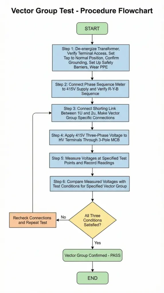
Step 1: Preparation and Safety Checks
Make sure the transformer is completely de-energized and isolated from all power sources. Verify that all HV and LV terminals are open and accessible for connections. Check that the transformer tap changer is set to the normal (principal) tap position. Confirm that the transformer tank is properly grounded. Set up safety barriers around the test area and ensure all personnel are wearing appropriate PPE.
Step 2: Verify Supply Phase Sequence
Connect the phase sequence meter to the 415V three-phase supply. Confirm that the supply has positive phase sequence (R-Y-B). If the phase sequence is incorrect, swap any two phases to correct it. This step is very important because an incorrect phase sequence will produce misleading test results.
Step 3: Make Test Connections
Connect the specified HV and LV terminals together according to the vector group being tested. The most common connection is to short the HV R-phase terminal (1U) to the LV r-phase terminal (2u) using a jumper cable. This creates a common reference point for voltage measurements. For star-connected windings with a neutral, the neutral point may need to be grounded or left floating depending on the specific vector group.
Step 4: Apply Test Voltage
Connect the 415V three-phase supply to the HV winding through a 3-pole MCB (Miniature Circuit Breaker). Apply voltage to the HV terminals 1U, 1V, and 1W. The LV winding will develop a proportional voltage based on the turns ratio.
Step 5: Measure and Record Voltages
Using the digital voltmeter, measure voltages at the specified test points for each vector group. Take measurements carefully and record all readings in a structured test data sheet. Repeat each measurement at least twice to confirm consistency.
Step 6: Compare with Test Conditions
Compare the measured voltages against the theoretical test conditions for the specified vector group. All three conditions must be satisfied for the vector group to be confirmed.
6. Connection Diagram for Vector Group Test
The basic connection arrangement for the vector group test is shown below. The 415V three-phase supply (R, Y, B phases) is connected through a 3-pole MCB to the HV bushings of the transformer (1U, 1V, 1W). A shorting link is placed between the HV terminal 1U and the LV terminal 2u. The LV terminals (2u, 2v, 2w) and the neutral point (if available) are kept accessible for voltage measurements.

Note that the HV terminals use uppercase notation (1U, 1V, 1W) and LV terminals use lowercase notation (2u, 2v, 2w) following IEC convention.
7. Detailed Test Conditions for Each Vector Group
Now let us go through the test conditions for each common vector group. For each vector group, three conditions must be satisfied simultaneously to confirm the correct vector group designation.
7.1 YNyn0 Vector Group Test
The YNyn0 vector group has both HV and LV windings connected in Star configuration with 0° phase displacement. Both neutral points are brought out. The LV phasor sits at the 12 o’clock position, meaning both windings are perfectly in phase.

Connection Method:
Connect HV R-phase terminal (1U) to LV r-phase terminal (2u) using a jumper cable. Keep the neutral points of both windings floating (not grounded). Apply 415V three-phase voltage to the HV winding.
Test Conditions to be Satisfied:
| Serial No | Condition |
| 1 | V(1U1N) = V(1U2n) + V(1N2n) |
| 2 | V(1W2w) = V(1V2v) |
| 3 | V(1W2w) < V(1W2v) |
Explanation: In a 0° displacement Star-Star transformer, the HV and LV phasors are aligned. Condition 1 verifies that the voltage across the HV phase winding equals the sum of two specific inter-winding voltages, which is only true when the phasors are in phase. Condition 2 confirms symmetry between phases. Condition 3 provides a magnitude check that distinguishes 0° displacement from other configurations.
7.2 YNyn6 Vector Group Test
The YNyn6 vector group has both HV and LV windings connected in Star configuration with 180° phase displacement. The LV phasor sits at the 6 o’clock position, meaning the LV winding voltages are completely opposite in polarity to the HV winding voltages.

Connection Method:
Connect HV R-phase terminal (1U) to LV r-phase terminal (2u) using a jumper cable. Keep the neutral points of both windings floating. Apply 415V three-phase voltage to the HV winding.
Test Conditions to be Satisfied:
| Serial No. | Condition |
| 1 | V(1N2n) = V(1U1N) + V(2u2n) |
| 2 | V(1W2v) = V(1V2w) |
| 3 | V(1w2w) > V(1W2v) |
Explanation: In a 180° displacement configuration, the phasors are inverted. Condition 1 shows that the neutral-to-neutral voltage equals the sum of the individual phase voltages — a hallmark of anti-phase alignment. The inequality in Condition 3 is reversed compared to YNyn0, which is how we distinguish between 0° and 180° displacement.
7.3 Dd0 Vector Group Test
The Dd0 vector group has both HV and LV windings connected in Delta configuration with 0° phase displacement. Since both windings are Delta-connected, there are no neutral points available.

Connection Method:
Connect HV R-phase terminal (1U) to LV r-phase terminal (2u) using a jumper cable. Since both windings are Delta-connected, there are no neutral points. Apply 415V three-phase voltage to the HV winding.
Test Conditions to be Satisfied:
| Serial No | Condition |
| 1 | V(1U1W) = V(1W2w) + V(1U2w) or V(1U1V) = V(1U2v) + V(1V2v) |
| 2 | V(1W2v) = V(1V2w) |
| 3 | V(1W2v) > V(1W2w) |
Explanation: The Delta-Delta 0° configuration means the line voltages on both sides are in phase. Condition 1 uses the relationship between HV line voltage and inter-winding voltages to confirm this alignment. Two alternative formulations are provided for Condition 1 — either one can be used.
7.4 Dd6 Vector Group Test
The Dd6 vector group has both HV and LV windings connected in Delta configuration with 180° phase displacement. The LV line voltages are exactly opposite in polarity to the HV line voltages.

Connection Method:
Connect HV R-phase terminal (1U) to LV r-phase terminal (2u) using a jumper cable. Both windings are Delta-connected. Apply 415V three-phase voltage to the HV winding.
Test Conditions to be Satisfied:
| Serial No | Condition |
|---|---|
| 1 | V(1W2w) = V(1W1U) + V(1U2w) |
| 2 | V(1W2w) = V(1V2v) |
| 3 | V(1V2v) > V(1V2w) |
Explanation: The 180° displacement in a Delta-Delta transformer inverts the voltage relationships compared to Dd0. Condition 1 shows that the inter-winding voltage V(1W2w) now equals the sum of V(1W1U) and V(1U2w), which only holds true when the LV phasor is anti-phase to the HV phasor.
7.5 YNd1 Vector Group Test
The YNd1 vector group has the HV winding connected in Star and the LV winding connected in Delta. The phase displacement is 30° lagging — the LV phasor sits at the 1 o’clock position, meaning the LV lags the HV by 30 degrees.

Connection Method:
Connect HV R-phase terminal (1U) to LV r-phase terminal (2u) using a jumper cable. The HV neutral point (1N) is used as a measurement reference point. Apply 415V three-phase voltage to the HV winding.
Test Conditions to be Satisfied:
| Serial No | Condition |
|---|---|
| 1 | V(1U1N) = V(2v1N) + V(1U2v) |
| 2 | V(1W2v) = V(1V2v) |
| 3 | V(1W2w) < V(1V2w) |
Explanation: The 30° lag means the LV Delta phasors are shifted clockwise by 30° relative to the HV Star phasors. The HV neutral (1N) serves as a convenient reference point for measurements since the Delta winding does not have a physical neutral point.
7.6 YNd11 Vector Group Test
The YNd11 vector group has the HV winding connected in Star and the LV winding connected in Delta. The phase displacement is 30° leading — the LV phasor sits at the 11 o’clock position, meaning the LV leads the HV by 30 degrees. This is one of the most common vector groups found in power transformers used in transmission systems.

Connection Method:
Connect HV R-phase terminal (1U) to LV r-phase terminal (2u) using a jumper cable. The HV neutral point (1N) should be connected to earth and used as a reference. Keep all other terminals open for measurements. Apply 415V three-phase voltage to the HV winding.
Test Conditions to be Satisfied:
| Serial No | Condition |
|---|---|
| 1 | V(1U1N) = V(1N2w) + V(1U2w) |
| 2 | V(1W2w) = V(1V2w) |
| 3 | V(1W2v) > V(1V2v) |
Explanation: The 30° lead means the LV Delta phasors are shifted counterclockwise by 30° relative to the HV Star phasors. Notice how Condition 3 has the inequality direction reversed compared to YNd1 — this is how the test distinguishes between the 1 and 11 clock positions.
7.7 Dyn1 Vector Group Test
The Dyn1 vector group has the HV winding connected in Delta and the LV winding connected in Star with the neutral brought out. The phase displacement is 30° lagging — the LV phasor sits at the 1 o’clock position.

Connection Method:
Connect HV R-phase terminal (1U) to LV r-phase terminal (2u) using a jumper cable. Connect the LV neutral point (2n) to earth. Apply 415V three-phase voltage to the HV winding.
Test Conditions to be Satisfied:
| Serial No | Condition |
|---|---|
| 1 | V(1U1W) = V(1W2n) + V(1U2n) |
| 2 | V(1W2w) = V(1W2v) |
| 3 | V(1V2w) > V(1V2v) |
Explanation: In the Dyn1 configuration, the Delta HV winding does not have a neutral, so the LV Star neutral (2n) serves as the grounding and reference point. Condition 2 shows a different symmetry relationship compared to the Dyn11 case, and the inequality in Condition 3 helps distinguish between the two.
7.8 Dyn11 Vector Group Test
The Dyn11 vector group has the HV winding connected in Delta and the LV winding connected in Star with the neutral brought out. The phase displacement is 30° leading — the LV phasor sits at the 11 o’clock position. Dyn11 is the most widely used vector group in distribution transformers worldwide. It is popular because the Delta primary provides a path for circulating third harmonic currents, and the Star secondary with neutral allows for single-phase loads and grounding.

Connection Method:
Connect HV R-phase terminal (1U) to LV r-phase terminal (2u) using a jumper cable. Ground the neutral point of the LV Star winding (2n). Apply 415V three-phase voltage to the HV winding.
Test Conditions to be Satisfied:
| Serial No | Condition |
|---|---|
| 1 | V(1U1V) = V(1V2n) + V(1U2n) |
| 2 | V(1V2w) = V(1V2v) |
| 3 | V(1W2v) > V(1W2w) |
Explanation: The Dyn11 test conditions are specifically designed to verify the 30° leading relationship between the Delta HV and Star LV windings. Condition 1 uses the HV line voltage V(1U1V) and its relationship with inter-winding voltages involving the LV neutral. Condition 3 inequality direction is opposite to Dyn1, providing a clear distinction between the two configurations.
7.9 Summary Table of Vector Group Test Conditions
The following table summarizes all test conditions for quick reference during field testing.
| Vector Group | Connection | Phase Shift | Condition 1 | Condition 2 | Condition 3 |
|---|---|---|---|---|---|
| YNyn0 | 1U-2u, N float | 0° | V(1U1N) = V(1U2n) + V(1N2n) | V(1W2w) = V(1V2v) | V(1W2w) < V(1W2v) |
| YNyn6 | 1U-2u, N float | 180° | V(1N2n) = V(1U1N) + V(2u2n) | V(1W2v) = V(1V2w) | V(1W2w) > V(1W2v) |
| Dd0 | 1U-2u | 0° | V(1U1W) = V(1W2w) + V(1U2w) | V(1W2v) = V(1V2w) | V(1W2v) > V(1W2w) |
| Dd6 | 1U-2u | 180° | V(1W2w) = V(1W1U) + V(1U2w) | V(1W2w) = V(1V2v) | V(1V2v) > V(1V2w) |
| YNd1 | 1U-2u | 30° lag | V(1U1N) = V(2v1N) + V(1U2v) | V(1W2v) = V(1V2v) | V(1W2w) < V(1V2w) |
| YNd11 | 1U-2u | 30° lead | V(1U1N) = V(1N2w) + V(1U2w) | V(1W2w) = V(1V2w) | V(1W2v) > V(1V2v) |
| Dyn1 | 1U-2u, N earth | 30° lag | V(1U1W) = V(1W2n) + V(1U2n) | V(1W2w) = V(1W2v) | V(1V2w) > V(1V2v) |
| Dyn11 | 1U-2u, N earth | 30° lead | V(1U1V) = V(1V2n) + V(1U2n) | V(1V2w) = V(1V2v) | V(1W2v) > V(1W2w) |
8. Measurement Recording Format
A well-organized test data sheet helps maintain accuracy and traceability. Here is a recommended format for recording vector group test results.
| Parameter | Measurement | Unit | Acceptable Range |
|---|---|---|---|
| Applied Voltage (Line-to-Line) | — | V | 415 ± 5% |
| Phase-1 HV Voltage V(1U,1N) or V(1U,1V) | — | V | Rated ±2% |
| Phase-2 HV Voltage V(1V,1N) or V(1V,1W) | — | V | Rated ±2% |
| Phase-3 HV Voltage V(1W,1N) or V(1W,1U) | — | V | Rated ±2% |
| Measurement Point 1 | — | V | As per Condition 1 |
| Measurement Point 2 | — | V | As per Condition 2 |
| Measurement Point 3 | — | V | As per Condition 3 |
| Vector Group Confirmed | Yes/No | — | All conditions met |
9. Acceptance Criteria
The vector group test is considered successful when all three test conditions are satisfied within acceptable tolerance. Measured voltages should match theoretical values derived from the phasor diagrams. The percentage deviation between measured and calculated values should be less than 2-3%. The phase sequence must be correctly identified. There should be no indication of winding faults or incorrect terminal connections.
10. Vector Groups and Parallel Operation of Transformers
One of the primary reasons for performing vector group testing is to verify that transformers are suitable for parallel operation. Let us discuss the requirements and compatibility rules in detail.
10.1 Requirements for Parallel Operation
For two or more transformers to operate successfully in parallel, the following conditions must be met.
Same vector group — this is mandatory and non-negotiable. Transformers with different vector groups will have different phase displacements, causing circulating currents at no-load.
Same voltage ratio — the turns ratio and tap positions must match. A mismatch in voltage ratio causes a voltage difference that drives circulating currents proportional to the ratio mismatch.
Same percentage impedance — if the percentage impedances differ, the transformers will not share load proportionally. The transformer with lower impedance will carry a larger share of the load.
Same X/R ratio — differences in the X/R ratio cause unequal sharing of reactive power between the paralleled transformers.
Same phase sequence — both transformers must be connected with the same phase sequence at their terminals.
10.2 Vector Group Compatibility for Parallel Operation
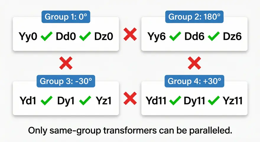
Transformers can be paralleled only if they belong to the same compatibility group. The four compatibility groups are:
Group 1 (0° displacement): Yy0, Dd0, Dz0 — these can be paralleled with each other.
Group 2 (180° displacement): Yy6, Dd6, Dz6 — these can be paralleled with each other.
Group 3 (30° lagging): Yd1, Dy1, Yz1 — these can be paralleled with each other.
Group 4 (30° leading): Yd11, Dy11, Yz11 — these can be paralleled with each other.
A transformer from Group 1 cannot be paralleled with a transformer from Group 2, 3, or 4. Similarly, a transformer from Group 3 cannot be paralleled with one from Group 4. There is a 60-degree phase difference between Group 3 and Group 4, which would produce dangerously high circulating currents if attempted.
10.3 What Happens with Incorrect Parallel Operation?
If two transformers with different vector groups are connected in parallel, the following consequences will occur:
Large circulating currents will flow between the transformers even with no external load connected. These currents can be several times the rated current of the transformers. The transformers will overheat rapidly due to the high circulating current, causing accelerated insulation degradation. Protective relays and circuit breakers may trip due to the overcurrent condition. In severe cases, the insulation may fail, leading to internal short circuits and possible transformer explosion. Personnel working near the transformers will be exposed to serious safety hazards.
This is why the vector group test is always performed before any attempt at parallel operation.
11. Common Vector Groups Used in Power Systems
Different vector groups serve different purposes in electrical power systems. Here is a quick overview of the most commonly used configurations.
Dyn11 is the most popular vector group for distribution transformers in the 11kV/415V class. The Delta primary eliminates third harmonics, and the Star secondary provides a neutral for single-phase loads and grounding.
YNyn0 is commonly used for auto-transformers and in transmission systems where the primary and secondary voltages are of similar magnitude.
YNd11 is used in generator step-up transformers and HV transmission transformers. The Star primary allows grounding at the generator voltage level, and the Delta secondary traps third harmonics.
Dd0 is less common but finds use in special applications where neither side requires a neutral point and zero-phase-shift is needed.
Dyn1 and YNd1 are used in certain regions and applications based on local utility standards and historical practices.
12. Conclusion
The vector group test is a mandatory pre-commissioning procedure that confirms the phase relationships and winding configurations of three-phase power transformers. This test protects transformers from the damaging effects of incorrect parallel operation. It also verifies that the manufacturer has built the transformer according to the specified design.
In this guide, we covered the vector group notation system, clock convention, and detailed test conditions for eight common vector groups — YNyn0, YNyn6, Dd0, Dd6, YNd1, YNd11, Dyn1, and Dyn11. We also discussed the practical procedure, equipment requirements, measurement recording format, and parallel operation compatibility rules.
Every transformer commissioning engineer should memorize or keep a printed copy of the vector group test conditions summary table for quick reference during field testing. Accurate execution of this test, combined with proper documentation, contributes directly to the safe and reliable operation of electrical power systems.
13. Frequently Asked Questions (FAQs)
The vector group test is a pre-commissioning test that verifies the phase displacement and winding connection arrangement between the HV and LV windings of a three-phase transformer. It is performed by applying a three-phase voltage to one winding and measuring voltages at specific terminal combinations to confirm the transformer’s vector group matches its nameplate designation.
Large circulating currents will flow between the transformers even at no-load condition. These circulating currents can cause severe overheating, insulation failure, protection system tripping, and in extreme cases, complete transformer failure.
Dyn11 is the most widely used vector group in distribution transformers around the world. The Delta primary winding provides a circulating path for third harmonic currents. The Star secondary winding with neutral provides a grounding point and allows connection of single-phase loads.
Yes, the vector group can be determined using a single-phase supply with specific terminal connections. However, the three-phase method described in this guide provides more accurate and reliable results because it tests all phases simultaneously and gives clearer voltage discrimination between different vector groups.
The standard test voltage is 415V three-phase AC applied to the HV winding. This voltage is convenient because it is readily available from standard industrial power supplies.
Dyn11 has a Delta HV winding and a Star LV winding with neutral. YNd11 has a Star HV winding with neutral and a Delta LV winding. Both have a 30° leading phase displacement. Dyn11 is commonly used in distribution transformers, and YNd11 is more common in generator step-up transformers and transmission applications.
Vector group testing is performed during factory acceptance testing, before initial commissioning at site, and after any major repair work that involves the transformer windings or bushing connections. It is not a routine periodic maintenance test because the vector group of a transformer does not change during normal operation.
The number represents the phase displacement between HV and LV windings using clock notation. Each number corresponds to 30 degrees of phase shift. For example, “11” means 11 × 30° = 330°, which is equivalent to the LV leading the HV by 30°. A “0” means 0° displacement and “6” means 180° displacement.
No. A Dyn1 transformer has 30° lagging displacement and a Dyn11 has 30° leading displacement. The phase difference between them is 60°, which would cause dangerous circulating currents if paralleled.
Modern Transformer Turn Ratio (TTR) testers and transformer analyzers have automatic vector group detection capabilities. These instruments apply test voltages phase by phase, measure the resulting voltages and phase angles, and determine the vector group automatically.