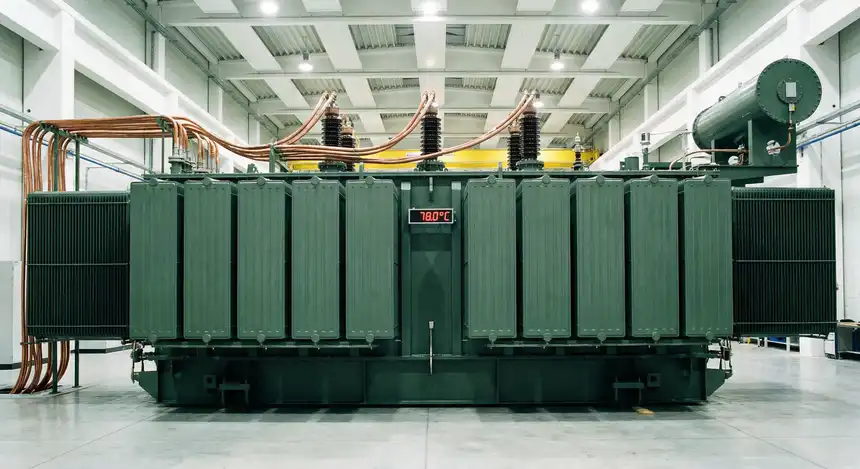
Every transformer generates heat during operation. This heat is a natural result of electrical losses occurring in the windings and the core. If the temperature inside a transformer exceeds safe limits, the insulation starts to degrade. Over time, this leads to reduced lifespan and even complete failure of the transformer. That is why measuring how much the temperature rises above the ambient during full-load operation is so important.
The temperature rise test is one of the most important type tests performed on power transformers and distribution transformers. It helps manufacturers and engineers verify that the transformer design can handle its rated load without overheating. This test is also a requirement under major international and national standards such as IEEE and IEC. Utilities and industrial buyers often require temperature rise test reports before accepting delivery of a new transformer.
In this technical guide, we will discuss everything you need to know about the temperature rise test for transformers, including its working principle, test methods, applicable standards, acceptance criteria, practical calculation examples, common challenges, and troubleshooting tips. Practical examples are included throughout to help you apply these concepts in real-world scenarios confidently.
1. What is the Temperature Rise Test for Transformers?
The temperature rise test measures how much the temperature of the transformer windings and oil increases above the surrounding ambient temperature during sustained loading conditions. The result is expressed in degrees Celsius (°C) and is called the “temperature rise.”
It is important to understand that the test does not measure the absolute temperature of the transformer. Instead, it measures the difference between the transformer’s operating temperature and the ambient temperature. For example, if the ambient temperature is 25°C and the average winding temperature reaches 90°C, the temperature rise is 65°C.
This test is performed at the factory before the transformer is shipped to the site. It falls under the category of “type test” or “design test” according to most standards. Some customers may also request it as a routine test for large power transformers or transformers intended for high-reliability applications.
2. Why is the Temperature Rise Test Important?
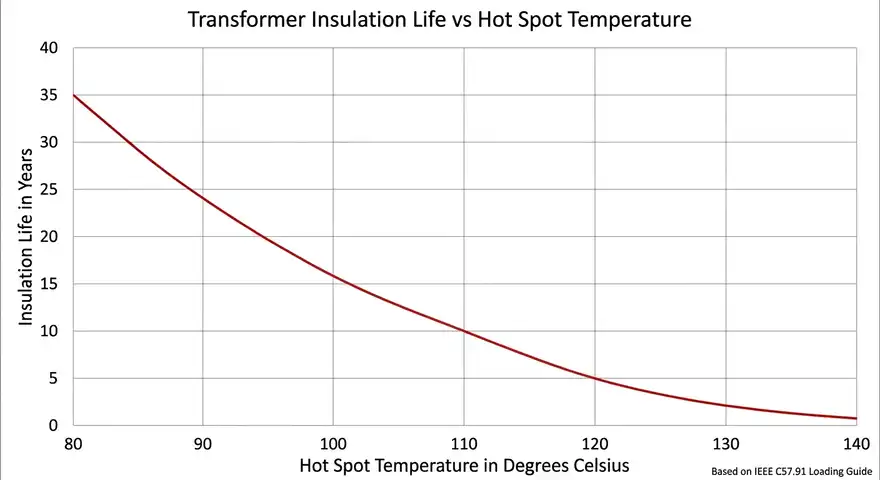
Heat is the primary enemy of transformer insulation. The life of a transformer is directly related to the thermal aging of its insulation. According to a well-known rule of thumb in electrical engineering, for every 6°C to 10°C increase above the rated hot spot temperature, the insulation life is roughly cut in half. This relationship makes it clear why controlling and verifying temperature rise matters so much.
Here are the main reasons this test holds such importance:
1. Insulation Life Verification: The insulation materials used in transformers are rated for specific temperature classes. If the actual temperature rise exceeds the design limit, the insulation will age faster and fail prematurely.
2. Cooling System Validation: The test confirms that the fans, radiators, oil pumps, and natural convection paths are working as intended. A transformer may look correct on paper, but the actual thermal performance can only be confirmed through testing.
3. Contractual and Standards Compliance: Buyers specify temperature rise limits in their purchase specifications. The test proves that the manufacturer has met those requirements.
4. Safety and Reliability: A transformer that runs too hot is a safety hazard. It can cause oil degradation, gas generation, and in extreme cases, fire or explosion.
3. Applicable Standards and Codes
Several international and national standards govern the temperature rise test for transformers. Engineers and test personnel should be familiar with the applicable standard for their region and application.
3.1 IEEE / ANSI Standards
- IEEE C57.12.00 – General requirements for liquid-immersed distribution, power, and regulating transformers. This standard specifies temperature rise limits for different insulation classes.
- IEEE C57.12.90 – Standard test code for liquid-immersed distribution, power, and regulating transformers. This standard describes the detailed test procedures for conducting the temperature rise test.
- ANSI C57.12.00 – This is essentially aligned with IEEE C57.12.00 and is widely referenced in North American specifications.
3.2 IEC Standards
- IEC 60076-2 – Power transformers – Part 2: Temperature rise for liquid-immersed transformers. This is the primary IEC standard covering temperature rise testing.
- IEC 60076-11 – Dry-type transformers. This standard covers temperature rise requirements for dry-type transformers.
3.3 Temperature Rise Limits (Per IEEE C57.12.00 / ANSI C57.12.00)
| Component | Insulation Class (105°C) | Insulation Class (220°C) |
|---|---|---|
| Average winding rise | 55°C | 150°C |
| Hot spot rise | 65°C | 180°C |
| Top oil rise | 55°C | — |
For modern transformers with 65°C rise insulation systems (which is the most common today):
| Component | Limit |
|---|---|
| Average winding temperature rise | 65°C |
| Hot spot temperature rise | 80°C |
| Top oil temperature rise | 65°C |
These values assume a maximum ambient temperature of 40°C and an average ambient temperature of 30°C over a 24-hour period as specified in ANSI C57.12.00.
4. Test Methods for Temperature Rise Test
There are three main methods used to conduct the temperature rise test on transformers. The choice of method depends on the size of the transformer, available test equipment, and the applicable standard.
4.1 Short-Circuit Method (Most Common)
This is the most widely used method for large power transformers. In this method, the test is divided into two phases:
4.1.1 Phase 1 – Total Loss Run (Heating Phase)
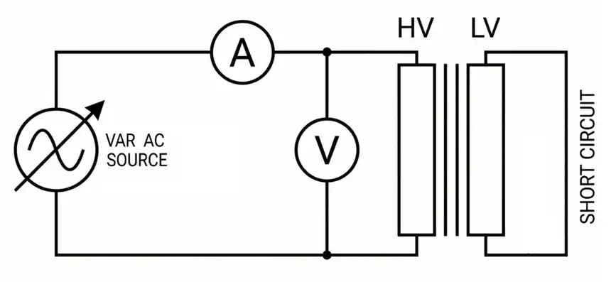
The transformer is short-circuited on one side (usually the LV side). A reduced voltage is applied to the other side (HV side) to circulate rated current through the windings. The applied voltage is adjusted so that the total losses (copper losses + iron losses) are injected into the transformer. Since a short-circuited transformer at rated current only requires a small fraction of rated voltage, the iron losses from this reduced voltage are much less than the actual iron losses at rated voltage. To compensate, additional current (slightly above rated) is circulated so that the total I²R losses plus stray losses equal the total losses of the transformer.
Alternatively, the iron losses can be supplied separately. In many test setups, the transformer is first energized at rated voltage with no load to generate iron losses. Then the load is applied to generate copper losses. Some laboratories combine both simultaneously.
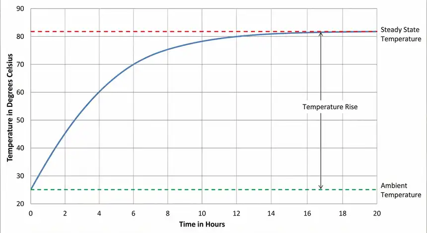
The heating run continues until the top oil temperature reaches a steady state. A steady state is achieved when the rate of temperature change is less than 1°C per hour for three consecutive hours. This process can take 8 to 20 hours depending on the transformer size.
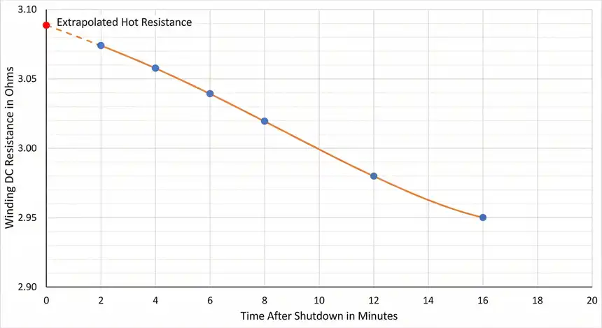
4.1.2 Phase 2 – Winding Resistance Measurement (Cooling Phase)
Immediately after the heating run is completed, the power supply is disconnected. The winding resistance is measured at several time intervals during the cooling period, starting as quickly as possible (ideally within 1 to 2 minutes after shutdown). These resistance readings are extrapolated back to the instant of shutdown to determine the winding temperature at the end of the heating run.
4.2 Back-to-Back Method (Opposed Test / Sumpner’s Test)
This method is used when two identical transformers are available. The two transformers are connected in parallel with their secondaries opposing each other. One supply provides the magnetizing current (at rated voltage) to generate iron losses. Another supply provides the circulating current (at rated current) to generate copper losses.
The advantage of this method is that the total power drawn from the supply is only equal to the total losses of the transformer, not the full rated power. This makes it suitable for testing very large transformers where a full-load test would require impractical amounts of power.
4.3 Actual Loading Method
In this method, the transformer is loaded at its rated kVA with an actual load bank. This is the most straightforward approach but is generally only practical for small distribution transformers. For large power transformers rated at several hundred MVA, providing a full-load test setup is extremely expensive and often impossible.
5. Step-by-Step Procedure for the Short-Circuit Method
Let us walk through the step-by-step procedure for performing a temperature rise test using the short-circuit method, which is the most common approach.
Step 1: Preparation
Record the ambient temperature using at least three thermometers placed around the transformer at a distance of 1 to 2 meters. The thermometers should be shielded from direct sunlight and heat radiation from the transformer. Note the transformer nameplate data including rated kVA, rated voltage, rated current, impedance, and total losses.
Step 2: Initial Resistance Measurement
Measure the DC resistance of all windings at the ambient temperature before starting the test. This cold resistance measurement will be used later to calculate the average winding temperature rise.
Step 3: Short-Circuit Connection
Short-circuit the LV terminals using heavy copper bus bars or cables rated for the full load current. Connect the variable power supply to the HV terminals.
Step 4: Heating Run
Apply voltage to circulate rated current through the windings. Adjust the current so that the total losses injected into the transformer match the total losses specified on the test report (sum of no-load losses and load losses). Monitor and record the top oil temperature at regular intervals (every 15 to 30 minutes). Continue the test until the top oil temperature reaches steady state.
Step 5: Shutdown and Resistance Measurement
Once steady state is reached, quickly disconnect the power supply. Immediately begin measuring the winding DC resistance. Take readings at multiple time points (for example, at 1, 2, 4, 8, 12, and 16 minutes after shutdown). Record the exact time of each measurement.
Step 6: Extrapolation
Plot the resistance values against time on a graph. Extrapolate the curve back to the instant of shutdown (time = 0) to determine the hot resistance of the winding at the end of the test.
Step 7: Calculation
Use the hot resistance value to calculate the average winding temperature. Then subtract the ambient temperature to get the average winding temperature rise.
6. Calculations Involved in the Temperature Rise Test
The temperature of the winding is determined indirectly through DC resistance measurement. The relationship between resistance and temperature for copper and aluminum conductors is well established.
6.1 Formula for Average Winding Temperature
For copper windings:
\(T_2 = \left(\dfrac{R_2}{R_1}\right) \times \left(T_1 + 234.5\right) − 234.5\)
For aluminum windings:
\(T_2 = \left(\dfrac{R_2}{R_1}\right) \times \left(T_1 + 225\right) − 225\)
Where:
- \(T_1 =\) Temperature at which cold resistance was measured (°C)
- \(T_2 =\) Average winding temperature at the end of the test (°C)
- \(R_1 =\) Cold resistance measured at temperature \(T_1 (\Omega)\)
- \(R_2 =\) Hot resistance extrapolated to the instant of shutdown \((\Omega)\)
- \(234.5 =\) Temperature constant for copper
- \(225 =\) Temperature constant for aluminum
6.2 Temperature Rise Calculation
Average Winding Temperature Rise = T₂ − Ambient Temperature during test
Top Oil Temperature Rise = Top Oil Temperature (steady state) − Ambient Temperature during test
6.3 Practical Example
Let us work through a practical example to make this clear.
Given Data:
- Transformer: 10 MVA, 66/11 kV, ONAN cooling
- Cold resistance of HV winding \((R_1): 2.500 \Omega\) at 25°C
- Hot resistance of HV winding \((R_2)\) extrapolated to shutdown instant: \(3.085 \Omega\)
- Ambient temperature during test: 28°C
- Top oil temperature at steady state: 82°C
Step 1: Calculate average winding temperature (copper winding)
\(T_2 = \left(\dfrac{3.085}{2.500}\right) \times (25 + 234.5) − 234.5\)
\(T_2 = 1.234 \times 259.5 − 234.5\)
\(T_2 = 320.22 − 234.5\)
\(T_2 = 85.72°C\)
Step 2: Calculate average winding temperature rise
\(\text{Average winding rise} = 85.72 − 28 = 57.72°C\)
Step 3: Calculate top oil temperature rise
\(\text{Top oil rise} = 82 − 28 = 54°C\)
Step 4: Compare with limits (per IEEE C57.12.00 for 65°C rise class)
- Average winding rise limit: 65°C → Measured: 57.72°C → PASS
- Top oil rise limit: 65°C → Measured: 54°C → PASS
The transformer passes the temperature rise test.
7. Hot Spot Temperature and Its Importance
The average winding temperature rise tells us the overall thermal condition of the winding. But the hottest point in the winding called the “hot spot” is always higher than the average. The hot spot is usually located near the top of the winding, where the oil temperature is highest and the heat dissipation is least effective.
The hot spot temperature is calculated using the following relationship:
Hot Spot Temperature = Top Oil Temperature + Hot Spot Gradient
The hot spot gradient is the difference between the hot spot temperature and the top oil temperature. It depends on the winding design, conductor size, insulation thickness, and oil flow pattern.
Per IEEE C57.12.00, the hot spot temperature rise limit for a 65°C rise transformer is 80°C above ambient. The hot spot factor (also called the hot spot multiplier) is usually between 1.1 and 1.3 for most transformer designs.
In practice, fiber optic temperature sensors are sometimes installed inside the winding during manufacturing to directly measure the hot spot temperature. This approach provides the most accurate data and is increasingly common for large power transformers.
8. Factors Affecting Temperature Rise in Transformers
Several factors influence the temperature rise during the test and during actual service conditions.
1. Transformer Losses: Higher losses mean more heat generation. Both no-load losses (core losses) and load losses (copper losses and stray losses) contribute to the total heat produced.
2. Cooling System Design: The type of cooling like ONAN (Oil Natural Air Natural), ONAF (Oil Natural Air Forced), OFAF (Oil Forced Air Forced), or ODAF (Oil Directed Air Forced) directly affects how efficiently heat is removed from the transformer.
3. Ambient Temperature: A higher ambient temperature results in a higher absolute operating temperature, even if the temperature rise remains the same. Transformers installed in hot climates may need derating or enhanced cooling.
4. Oil Quality: Degraded or contaminated transformer oil has reduced thermal conductivity. This leads to higher temperature gradients within the transformer.
5. Winding Design: The conductor cross-section, number of turns, and arrangement of cooling ducts within the winding all influence how well heat is transferred from the conductors to the oil.
6. Altitude: At higher altitudes, the air is thinner and less effective at cooling. Standards such as IEEE C57.12.00 require derating of the temperature rise limits for installations above 1000 meters.
9. Test Duration and Practical Challenges
The temperature rise test is one of the longest tests performed on transformers. It commonly takes 10 to 24 hours to complete. For very large power transformers with ONAN cooling, the time to reach thermal steady state can exceed 20 hours.
9.1 Common Challenges
1. Achieving Steady State: Ambient temperature fluctuations during a long test can make it difficult to confirm that steady state has been reached. Testing during nighttime or in temperature-controlled facilities helps reduce this issue.
2. Quick Resistance Measurement: After shutdown, the winding temperature drops rapidly. The resistance measurement must begin within 1 to 2 minutes. Any delay introduces error in the extrapolation. Modern digital resistance meters with automatic recording capabilities have greatly improved this process.
3. Power Supply Limitations: Injecting total losses into a large transformer requires a power supply capable of handling significant current at low voltage. Test facilities need appropriately rated variable voltage sources and current transformers.
4. Multiple Cooling Modes: Many large transformers have multiple cooling stages (for example, ONAN/ONAF/OFAF). The temperature rise test must be performed for each cooling mode, which multiplies the test duration.
5. Tap Position Effects: The test is usually performed at the principal tap. However, some specifications require testing at extreme tap positions as well, since the losses change with tap position.
10. Relationship Between Temperature Rise and Transformer Loading
In practice, transformers are not always operated at exactly rated load. They may be overloaded for short periods or operated at partial load most of the time.
The temperature rise test result helps engineers determine how much overloading a transformer can tolerate. IEEE C57.91 (Guide for Loading Mineral-Oil-Immersed Transformers) provides detailed guidance on this topic. It uses the temperature rise test data as input to calculate the loss of insulation life and maximum allowable loading under different conditions.
For example, a transformer with a measured temperature rise of 55°C (against a limit of 65°C) has a 10°C margin. This margin can be used to allow temporary overloading without exceeding the hot spot temperature limit. The exact overloading capacity depends on the transformer’s thermal time constants, which are derived from the temperature rise test.
This relationship between temperature rise test results and transformer loading guides is one of the reasons why accurate test data is so valuable for asset management and power system planning.
11. Preventive Maintenance and Temperature Monitoring in Service
The temperature rise test is conducted at the factory. But temperature monitoring continues throughout the transformer’s service life. Utilities and industrial operators use several tools to monitor transformer temperatures in the field:
1. Oil Temperature Indicators (OTI): These measure the top oil temperature using a bulb-type or electronic sensor installed in the top portion of the transformer tank.
2. Winding Temperature Indicators (WTI): These simulate the winding hot spot temperature using a combination of the oil temperature and a heater element driven by a CT (current transformer) output proportional to the load current.
3. Fiber Optic Sensors: Direct measurement of the winding hot spot temperature using fiber optic probes embedded in the winding. This is the most accurate method available.
4. Dissolved Gas Analysis (DGA): While not a temperature measurement method, DGA can detect thermal faults by identifying gases generated due to overheating.
Regular comparison of field temperature data with the original temperature rise test report helps identify cooling system degradation, oil pump failures, blocked radiators, or other problems before they cause a failure.
12. Conclusion
The temperature rise test is one of the most important performance verification tests for transformers. It directly demonstrates whether a transformer can operate at its rated load without exceeding safe temperature limits. The test validates the design of the cooling system, the adequacy of the insulation class, and the overall thermal performance of the transformer.
Engineers and test professionals should have a solid understanding of the test procedures, applicable standards like IEEE C57.12.00, IEEE C57.12.90, and IEC 60076-2, and the calculations involved. Accurate execution of this test and proper interpretation of results protect the transformer investment and support reliable power system operation for decades.
The temperature rise test data also serves as a baseline for ongoing condition monitoring and loading decisions throughout the transformer’s operational life. Every electrical engineer working with transformers should appreciate the value of this test and the information it provides.
13. Frequently Asked Questions (FAQs)
The purpose is to verify that the transformer’s temperature rise at rated load does not exceed the limits specified by applicable standards such as IEEE C57.12.00 or IEC 60076-2. It confirms that the cooling system is adequate and the insulation will not be subjected to excessive thermal stress.
The test duration varies based on transformer size and cooling type. For small distribution transformers, it may take 6 to 10 hours. For large power transformers with ONAN cooling, it can take 15 to 24 hours or even longer.
The average winding temperature rise is the overall average temperature increase of the entire winding above ambient. The hot spot temperature rise is the temperature increase at the hottest point of the winding above ambient. The hot spot is always higher than the average.
If the measured rise exceeds the standard limit, the transformer fails the test. The manufacturer must investigate the cause and take corrective action. This may involve adding more radiators, improving oil circulation, or modifying the winding design.
The temperature rise test is normally a factory test. Performing it at site is very difficult due to the need for precise power supplies, controlled ambient conditions, and quick resistance measurement equipment. However, field temperature monitoring can provide ongoing data to compare with factory test results.
For the 65°C rise insulation system (most common), the average winding temperature rise limit is 65°C and the top oil temperature rise limit is 65°C above a 30°C average ambient.
Thermocouples can only measure the temperature at the point where they are placed. They cannot capture the average temperature of the entire winding. The resistance method gives the true average winding temperature because the resistance of the entire winding conductor changes uniformly with temperature.
Per IEEE C57.12.90, the temperature rise test is classified as a design test (type test). It is not performed on every transformer unit produced. However, customers may request it as a special test for specific orders.