A Star Delta Starter is one of the most widely used reduced voltage starting methods for three-phase induction motors in industrial plants. It is also known as a Wye-Delta Starter in regions that follow ANSI/NEMA standards. This starting method is preferred for motors rated above 75kW because it limits the high inrush current during startup effectively.
In our plant, we use Star Delta Starters for induction motors rated at 90kW and above. These motors operate on a 440V three-phase power supply. The starter first connects the motor windings in star configuration during startup. Once the motor reaches approximately 80% of its full load speed, the circuit automatically transitions to delta configuration. This entire process happens within a few seconds through a timer-controlled switching mechanism.
Many engineers and electricians are familiar with the theoretical circuit diagrams of a Star Delta Starter. However, very few have seen what a Star Delta Starter actually looks like inside a real motor control panel. That is exactly what this article focuses on.
In this practical guide, we will discuss everything you need to know about the Star Delta Starter in real-world applications, including its actual components, contactor arrangement, overload relay settings, motor terminal connections, control circuit elements, and measuring instruments. Real photographs from an actual industrial Star Delta Starter panel are included throughout to help you visualize and apply these concepts in your workplace confidently.
1. Why is a Star Delta Starter Used in Industrial Applications?
A three-phase induction motor draws an extremely high current at the moment of starting. This high current is commonly referred to as inrush current or starting current. The inrush current can be 6 to 8 times the full load current of the motor. This happens because the rotor is stationary before starting and there is no back EMF (counter electromotive force) to oppose and limit the current flow.
If this inrush current is not controlled, it can cause serious problems. The motor windings can overheat and suffer insulation damage. The voltage at the supply bus can drop sharply, affecting other equipment connected to the same electrical system. In extreme cases, the motor can burn out completely during the starting period.
A Star Delta Starter solves this problem by reducing the voltage applied to each motor winding during startup. In star configuration, each winding receives only 1/√3 (approximately 57.7%) of the full line voltage. As a result, the starting current is reduced to approximately one-third (1/3) of the Direct-On-Line (DOL) starting current. The starting torque is also reduced to one-third of the DOL starting torque.
After a preset time delay of around 5 to 10 seconds, the timer triggers the transition from star to delta. In delta configuration, each winding receives the full line voltage and the motor runs at its rated capacity. This method of motor starting is both cost-effective and reliable for large industrial motors.
As per ANSI/NEMA ICS 2 standards, motor starters must be designed to handle the electrical and mechanical stresses during starting. The Star Delta Starter meets these requirements for reduced voltage starting applications.
2. What Does a Practical Star Delta Starter Look Like?
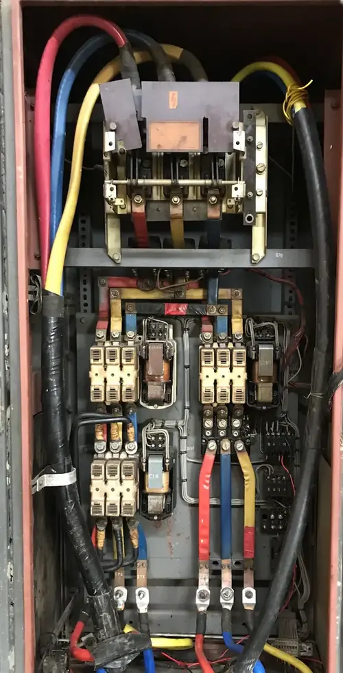
Most textbooks and online resources show the circuit diagram of a Star Delta Starter. But the actual physical layout inside a motor control panel looks quite different from the schematic. The components are arranged in a compact enclosure with heavy-duty wiring and bus bars connecting them together.
The photograph above shows a real Star Delta Starter panel used in our plant for a 90kW induction motor. You can see the isolator mounted at the top section of the panel. The three contactors are arranged in the middle section. The outgoing power cables exit from the bottom of the panel toward the motor terminal box.
Let us now go through each component one by one and understand its function and placement inside the starter panel.
3. Components of a Star Delta Starter
3.1 Isolator (Disconnecting Switch)
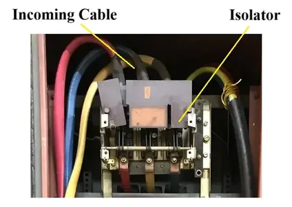
The isolator is the first component in the power flow path of a Star Delta Starter. It is mounted at the top section of the starter panel. The incoming three-phase power cable from the supply source connects directly to this isolator.
An isolator is a manually operated switching device. Its primary purpose is to disconnect the starter from the main power supply during maintenance or repair work. Once the isolator handle is turned to the OFF position, the entire starter panel becomes de-energized.
Some isolators come with built-in HRC (High Rupturing Capacity) fuses. These fuses provide short-circuit protection for the downstream circuit and motor. If a severe fault occurs, the fuse element melts and breaks the circuit before the fault current can damage the contactors or motor windings.
According to ANSI/NEMA ICS 2 and NEC Article 430, every motor circuit must have a disconnecting means that can isolate the motor and its controller from the supply. The isolator serves this exact purpose in a Star Delta Starter.
During any maintenance activity, always turn the isolator to the OFF position first. Apply a lockout/tagout (LOTO) device on the isolator handle. Then verify with a multimeter that no voltage is present at the contactor terminals before touching any internal component.
3.2 Contactors (Main, Star, and Delta)
The contactors are the heart of the Star Delta Starter. A contactor is an electrically operated switching device that can make or break the motor power circuit remotely. It is controlled through a low-voltage control circuit using ON and OFF push buttons.
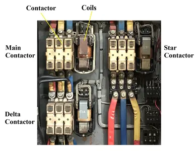
A Star Delta Starter uses three contactors:
- Main Contactor (KM1): This contactor connects the incoming three-phase supply to one end of the motor windings. It remains closed during both star and delta modes of operation.
- Star Contactor (KM2): This contactor short-circuits the other ends of the motor windings together to form the star (Y) connection. It remains closed only during the starting period.
- Delta Contactor (KM3): This contactor connects the motor winding ends to the supply lines to form the delta (Δ) connection. It closes after the star contactor opens.
Sequence of Operation:
- The operator presses the START button.
- The Main Contactor (KM1) and Star Contactor (KM2) close simultaneously.
- The motor starts running in star configuration with reduced voltage across each winding.
- The timer begins counting.
- After the preset time (say 5 seconds), the timer sends a signal.
- The Star Contactor (KM2) opens first.
- After a brief delay of about 50 milliseconds, the Delta Contactor (KM3) closes.
- The motor now runs in delta configuration at full voltage.
A very important point to note: The Star Contactor and Delta Contactor must never close at the same time. If both close simultaneously, it will create a direct short circuit across the three-phase supply. To prevent this, electrical interlocking is provided in the control circuit. The normally closed (NC) auxiliary contact of the Star Contactor is wired in series with the Delta Contactor coil circuit and vice versa. Some starters also use mechanical interlocking between the Star and Delta Contactors for added safety.
Are all three contactors of the same rating? Not necessarily. In many practical installations, the Main Contactor is rated for the full line current of the motor. The Star Contactor handles only the starting current for a short duration and can sometimes be of a lower rating. The Delta Contactor carries approximately 1/√3 (about 58%) of the line current during normal running. However, in our plant, all three contactors are of the same rating for standardization and ease of replacement.
Each contactor has an electromagnetic coil. This coil is energized from the control circuit. The coil creates a magnetic field that pulls the moving contacts toward the fixed contacts and closes the power circuit. The coil voltage is usually 240V AC or 110V AC depending on the control transformer used in the panel.
3.3 Thermal Overload Relay (OLR)
The Thermal Overload Relay is the primary protective device in a Star Delta Starter for motor overload protection. It protects the motor from sustained overcurrent conditions that can damage the stator windings.
A Thermal Overload Relay is an electromechanical device. It contains bimetallic strips that heat up when current flows through them. If the motor draws current above the set value for a prolonged period, the bimetallic strips bend and trigger a trip mechanism. This trip mechanism opens the control circuit and de-energizes the contactor coils. As a result, all contactors open and the motor stops.
The overload relay works on an inverse time characteristic. This means that the higher the overcurrent, the faster the relay trips. For example, if the overload setting is 150A and the motor draws 170A, the relay may trip after about 10 minutes. But if the motor draws 300A, the relay will trip within a few seconds.
Setting the Overload Relay:
For the Star Delta Starter shown in our photographs, the motor has a full load current (FLC) of 151 Amps. The overload relay is set at approximately 150A. This setting should be between 100% and 105% of the motor’s full load current as a general guideline.
The thermal overload relay does not protect against short circuits. Short-circuit protection is provided by the HRC fuses in the isolator or by an upstream circuit breaker (MCCB). Both types of protection must work together to keep the motor safe.
3.4 Control Circuit
The control circuit is a low-voltage circuit that governs the operation of all three contactors in the Star Delta Starter. It is the brain of the entire starting system. The control circuit includes the following components:
- Control Fuses: These fuses protect the control circuit wiring and components from short circuits. If a control wire develops a fault, the control fuse blows and prevents further damage.
- ON (Start) Push Button: This is a momentary normally open (NO) push button. Pressing it energizes the main contactor coil and star contactor coil to start the motor. A holding contact (auxiliary NO contact of the main contactor) keeps the circuit latched after the button is released.
- OFF (Stop) Push Button: This is a normally closed (NC) push button. Pressing it breaks the control circuit and de-energizes all contactor coils. The motor stops immediately.
- Timer: The timer is a very important component in the control circuit. It controls the time delay between the star and delta transition. The timer starts counting as soon as the motor starts in star mode. After the preset time expires, the timer output switches. This de-energizes the star contactor coil and energizes the delta contactor coil.
- Auxiliary Contacts (NO/NC): These are small contacts mounted on the contactors. They are used for interlocking, holding circuits, and indication purposes.
- Contactor Coils: Each contactor has an electromagnetic coil that is powered from the control circuit. The coil voltage is stepped down from the main supply using a control transformer in some designs.
The ON and OFF push buttons are usually mounted in a push button station located near the motor at the field location. Control cables run from this push button station back to the starter panel.
3.5 Measuring Instruments (Ammeter and Current Transformers)
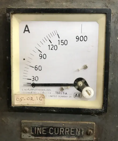
The measuring circuit in a Star Delta Starter helps the operator monitor the motor’s electrical parameters during operation. It usually consists of an ammeter and current transformers (CTs). Some panels also include a voltmeter for voltage measurement.
Current Transformers (CTs): A CT is an instrument transformer that steps down the high line current to a lower measurable value. For example, the ammeter shown in our photograph has a CT ratio of 150/5A. This means when the motor draws 150A through the primary conductor, the CT secondary produces 5A. The ammeter is calibrated to read the primary current directly.
Ammeter: The ammeter displays the motor’s line current. In the photograph, you can notice the ammeter has two scales. The normal scale reads up to 150A for regular operating current. The extended scale reads up to 900A for capturing the high inrush current during motor startup. This dual-scale feature is very useful for observing the current spike during starting and the normal running current after the transition to delta.
4. Motor Terminal Block Connection in Star Delta Starter
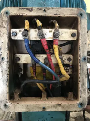
The motor terminal block connection in a Star Delta Starter is different from a DOL (Direct-On-Line) starter. In a DOL starter, the motor terminal box has links or jumper plates that connect the windings either in permanent star or permanent delta. But in a Star Delta Starter, these links are removed completely. All six terminals of the motor are left independent.
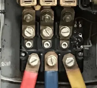
The motor terminal box has six terminals labeled as U1, V1, W1 (winding start terminals) and U2, V2, W2 (winding end terminals). The photograph above shows a real motor terminal box with all six terminals clearly visible.
Two separate sets of three-core cables run from the starter panel to the motor terminal box:
- First cable set comes from the Main Contactor output and connects to terminals U1, V1, W1.
- Second cable set comes from the Star/Delta Contactor output and connects to terminals U2, V2, W2.
During star mode, the Star Contactor shorts terminals U2, V2, and W2 together at the starter panel end. This creates the star point. Each winding receives only 1/√3 of the line voltage.
During delta mode, the Delta Contactor connects U2 to V1, V2 to W1, and W2 to U1 at the starter panel end. This creates the delta connection. Each winding now receives the full line voltage.
5. Safety Precautions for Star Delta Starter Maintenance
Working on a Star Delta Starter involves handling high-voltage and high-current electrical equipment. Following proper safety procedures is absolutely necessary.
- Turn OFF the isolator before opening the starter panel door. Move the isolator handle to the OFF position firmly.
- Apply Lockout/Tagout (LOTO) on the isolator. Use a padlock and a danger tag with your name and date. This prevents someone else from turning the isolator ON while you are working inside the panel.
- Verify zero voltage using a properly rated voltmeter or multimeter. Check between all phase-to-phase and phase-to-ground combinations at the contactor terminals.
- Never bypass the thermal overload relay. Some maintenance personnel bypass the overload relay to keep the motor running after a trip. This is extremely dangerous and removes the only overload protection the motor has.
- Wear appropriate PPE including insulated gloves, safety shoes, and safety glasses. For panels rated above 240V, an arc flash risk assessment should be performed as per NFPA 70E standards.
- Do not touch the contactor coils immediately after de-energizing. The coils can retain residual magnetism and some control circuits may have capacitors that hold charge.
6. Common Troubleshooting Tips for Star Delta Starters
Here are some common problems you may encounter with Star Delta Starters in the field and how to diagnose them:
6.1 Motor does not start at all
- Check if the isolator is in the ON position.
- Check the control fuses. A blown control fuse will prevent the contactor coils from energizing.
- Check the overload relay. If it has tripped, the reset button needs to be pressed.
- Check the START/STOP push button wiring for loose connections.
6.2 Motor starts in star but does not switch to delta
- The timer may be faulty. Check the timer output by measuring voltage at the delta contactor coil terminals.
- The delta contactor coil may be burnt out. Measure the coil resistance with a multimeter.
- The auxiliary interlock contact of the star contactor may be stuck or damaged.
6.3 Motor trips on overload immediately after switching to delta
- The timer setting may be too short. If the motor has not reached sufficient speed in star mode, the current spike during delta transition will be very high. Increase the timer delay.
- The overload relay setting may be too low. Verify the setting against the motor nameplate FLC.
- There may be a mechanical problem with the driven equipment causing excessive load.
6.4 Loud humming but motor does not rotate:
- This usually indicates a single phasing condition. One phase of the supply may be missing. Check all three phases at the motor terminal box.
- Check for a blown fuse in the isolator.
7. Conclusion
The Star Delta Starter remains one of the most common and cost-effective motor starting solutions in industrial electrical systems. It reduces the starting current to one-third of the DOL value and protects both the motor and the power distribution network from electrical stress during startup.
In this article, we explored the actual components of a Star Delta Starter using real photographs from an industrial installation. We covered the isolator, contactors, thermal overload relay, control circuit, measuring instruments, and motor terminal connections in detail. We also discussed the star-to-delta transition, interlocking, safety precautions, and the troubleshooting tips for this starting method.
8. Frequently Asked Questions (FAQs)
A DOL (Direct-On-Line) Starter connects the motor directly to the full supply voltage during starting. This results in a very high inrush current of 6 to 8 times the full load current. A Star Delta Starter first starts the motor in star configuration at reduced voltage and then switches to delta at full voltage. The starting current in a Star Delta Starter is reduced to approximately one-third of the DOL starting current.
No. The motor must have all six winding terminals brought out to the terminal box. The motor must also be rated for delta connection at the available supply voltage. For example, on a 440V supply, the motor should be rated 440V in delta. If the motor nameplate shows only a star rating of 440V, you cannot use a Star Delta Starter on a 440V supply because the delta voltage would be too high for the windings.
The overload relay setting depends on its placement in the circuit. If the overload relay is placed in the main line (between the main contactor and the star/delta junction), set it at 100% to 105% of the motor’s full load current.
If both contactors close simultaneously, it creates a direct short circuit across the three-phase power supply. This will result in an extremely high fault current that can destroy the contactors, damage the bus bars, blow the fuses, and may even cause an arc flash.
This usually happens because the timer setting is too short. If the motor has not accelerated to at least 75-80% of its full speed during the star period, the current drawn during the delta transition will be very high. Increasing the timer delay allows the motor more time to accelerate in star mode.
In star configuration, the starting current is approximately one-third (1/3) of the DOL starting current. For example, if a motor draws 900A during DOL starting, it will draw approximately 300A during star delta starting.
Yes. A Variable Frequency Drive (VFD) or soft starter can replace a Star Delta Starter. A VFD offers much smoother starting with adjustable acceleration and deceleration profiles.
The timer setting depends on the motor size, load inertia, and application. For most industrial motors in the 75kW to 150kW range, a timer setting of 5 to 15 seconds is common.
The timer controls the automatic transition from star mode to delta mode. It starts counting as soon as the motor begins running in star configuration. After the preset time expires, the timer output de-energizes the star contactor coil and energizes the delta contactor coil.
No. The starting torque in star mode is only one-third of the DOL starting torque. Applications that require high starting torque such as loaded conveyors, crushers, and ball mills are not suitable for Star Delta starting.