When a power transformer is switched on or energized, it draws an extremely high current for a brief period—often 5 to 30 times its full-load current. This phenomenon, known as transformer inrush current or magnetizing inrush current, is a critical concept that every electrical engineer must understand to ensure safe transformer operation, proper protection coordination, and reliable power system performance.
Transformer inrush current knowledge is essential for designing protection systems, sizing circuit breakers, selecting proper fuses, and preventing nuisance tripping that can disrupt power supply to critical loads.
In this technical guide we will discuss what transformer inrush current is, why it occurs, how to calculate it, and most importantly, how to mitigate its effects using proven engineering techniques.
What is Transformer Inrush Current?
Transformer inrush current is the instantaneous high-magnitude current drawn by the primary winding of a transformer when it is first energized with the secondary winding open-circuited or under no-load conditions. This transient current exists for a very short duration (typically 0.1 to 1 second), but its magnitude can be extremely high, ranging from 5 to 30 times the transformer’s full-load current (FLC).
During normal steady-state operation, a transformer draws a small magnetizing current to establish the required magnetic flux in its core. However, during the energization process, the magnetic flux in the core must rise from zero (or from residual flux levels) to its steady-state value. If the transformer is energized at an unfavorable instant in the voltage cycle, the resulting flux can temporarily exceed the core’s saturation limit, causing the core to saturate deeply.
When the transformer core saturates, its magnetic permeability drops and the impedance offered by the primary winding decreases substantially. This sharp reduction in impedance allows an extremely large current (the inrush current) to flow from the source into the primary winding.
This phenomenon is purely electromagnetic in nature and does not create any permanent damage to the transformer under normal conditions. However, it can cause several operational challenges if not properly managed.
Why Does Transformer Inrush Current Occur?
To fully understand why transformer inrush current occurs, we need to examine the relationship between voltage, flux, and current in a transformer during the energization process.
The Voltage-Flux Relationship
According to Faraday’s law of electromagnetic induction, when an alternating voltage is applied to the primary winding of a transformer, it induces a time-varying magnetic flux in the core. The relationship between voltage and flux is given by:
\(V = N \time \frac{d\Phi}{dt}\)
Where:
- V is the applied voltage
- N is the number of turns in the primary winding
- Φ is the magnetic flux
- dΦ/dt is the rate of change of flux
This equation tells us that the flux waveform lags the voltage waveform by 90 degrees during steady-state operation. When the voltage is at its maximum value, the rate of change of flux (dΦ/dt) is maximum, and when the voltage crosses zero, the flux reaches its peak value.
The Doubling Effect: Core Saturation During Energization
During steady-state operation, if the voltage is at zero at time t=0, the flux should ideally be at its maximum negative value. However, when a transformer is switched on at the instant when the applied voltage is zero, the flux cannot instantaneously jump to its maximum negative value, it must start from zero (or from the residual flux value if any remains in the core from previous operation).
Since the flux must follow the integral of the voltage waveform, and it starts from zero instead of its maximum negative value, the flux builds up to twice its normal steady-state peak value during the first half-cycle. This phenomenon is called the doubling effect.
Maximum Transient Flux = 2 × Normal Steady-State Flux
This doubled flux drives the transformer core deep into saturation. Once the core saturates, the relationship between flux and magnetizing current becomes highly nonlinear—a small increase in flux requires a dramatically large increase in current. This is why the inrush current magnitude becomes so high.
Factors Contributing to Inrush Current
The magnitude and duration of transformer inrush current depend on several interrelated factors:
| Factor | Effect on Inrush Current |
|---|---|
| Switching angle (voltage phase) | Maximum at zero crossing, minimum at voltage peak |
| Residual flux in core | High residual flux increases inrush magnitude |
| Transformer size (MVA rating) | Larger transformers produce higher inrush |
| System impedance | Low impedance allows higher peak currents |
| Core material properties | Better permeability reduces inrush |
| Core flux density design | Higher flux density design increases inrush |
| Temperature | Cold conditions may delay flux stabilization |
1. Switching Angle (Point on Voltage Wave)
The instant at which the transformer is energized has the most significant impact on inrush current magnitude. If the transformer is switched on when the voltage waveform is passing through zero (0° or 180°), the resulting inrush current is maximum. Conversely, if energization occurs when the voltage is at its peak (90° or 270°), the inrush current is minimal or may even be absent.
This is because switching at voltage peak ensures that the flux starts from zero and rises to only its normal steady-state maximum value, avoiding core saturation. This principle forms the basis of point-on-wave switching techniques for inrush mitigation.
2. Residual Flux in the Core
When a transformer is de-energized, some amount of magnetic flux remains trapped in the core material due to its hysteresis properties. This is called residual flux or remanent flux, and its magnitude can be as high as 70-80% of the rated peak flux density.
If the transformer is re-energized such that the initial flux change is in the same direction as the residual flux, the total flux can reach extremely high values (potentially up to 2.5 to 2.8 times the normal peak flux), causing severe core saturation and very high inrush currents.
3. Transformer Size and Rating
Larger transformers with higher MVA ratings typically produce higher inrush current magnitudes. This is because they have larger core volumes, store more magnetic energy, and have lower per-unit impedance values. A small distribution transformer (< 1 MVA) might have inrush currents of 5-8 times FLC, while large power transformers (> 10 MVA) can experience inrush currents of 10-14 times FLC or even higher.
4. System Source Impedance
The impedance of the supply system plays a crucial role in limiting inrush current. A stiff supply system with low source impedance allows higher peak inrush currents to flow, whereas higher system impedance naturally limits the current magnitude. However, higher system impedance also causes greater voltage dips during energization.
5. Core Material and Design
Modern transformers use high-grade cold-rolled grain-oriented (CRGO) silicon steel with superior magnetic properties. These materials have lower core losses and allow operation at higher flux densities (typically 1.6-1.8 Tesla), which improves efficiency. However, this also means the core operates closer to its saturation knee point, resulting in higher inrush currents compared to older transformers that operated at lower flux densities.
Characteristics of Transformer Inrush Current
Transformer inrush current has several distinctive characteristics that help distinguish it from other types of currents, particularly fault currents. Understanding these characteristics is essential for proper protection relay design and coordination.
Waveform Shape and Nature
The inrush current waveform is highly asymmetrical and peaky, quite different from the smooth sinusoidal waveform of normal load current or even short-circuit fault current. The waveform has the following features:
- Unidirectional peaks: The current peaks are predominantly in one direction during the initial cycles
- Strong DC component: The waveform contains a significant DC offset that decays gradually
- Exponential decay: The magnitude decreases exponentially over time as the flux stabilizes
- Non-sinusoidal shape: The waveform is highly distorted due to core saturation nonlinearity
Harmonic Content
One of the most important distinguishing features of inrush current is its rich harmonic content. When the core is saturated, the relationship between current and flux becomes nonlinear, producing significant harmonic components:
- Second harmonic: Typically 30-70% of the fundamental frequency component
- Third harmonic: Usually 10-30% of the fundamental
- Higher-order harmonics: Present but in smaller magnitudes
The predominance of the second harmonic (100 Hz in 50 Hz systems, 120 Hz in 60 Hz systems) is particularly useful because fault currents typically contain less than 20% second harmonic. This difference forms the basis of second harmonic restraint techniques used in transformer differential protection relays.
Duration and Decay Pattern
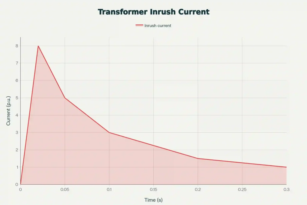
Inrush current is a transient phenomenon that decays over time as the magnetic flux in the core stabilizes and returns to its normal alternating pattern. The typical duration is:
- Initial peak: Maximum magnitude occurs in the first cycle (0.02 seconds in 50 Hz systems)
- Significant magnitude: Remains at 2-5 times FLC for 0.1-0.3 seconds
- Complete decay: Returns to normal magnetizing current within 0.3-1.0 seconds
The exact decay time depends on the system damping provided by resistance in the circuit and the transformer’s magnetic properties.
| Transformer Type/Rating | Typical Inrush (times FLC) | Duration (seconds) |
|---|---|---|
| Distribution transformer (< 1 MVA) | 5-8 times | 0.1-0.5 |
| Distribution transformer (1-10 MVA) | 8-12 times | 0.2-0.8 |
| Power transformer (> 10 MVA) | 10-14 times | 0.3-1.0 |
| Toroidal transformers | Up to 60 times | 0.1-0.3 |
| Dry-type transformers | 6-10 times | 0.1-0.6 |
| Oil-filled transformers | 8-12 times | 0.2-0.8 |
Inrush Current vs. Fault Current: Key Differences
It is critically important to distinguish between inrush current and internal fault current, as both appear as differential currents to protection relays but require completely different responses. Incorrect discrimination can lead to either nuisance tripping (false trip during inrush) or failure to trip (missing a real fault).
| Parameter | Inrush Current | Internal Fault Current |
|---|---|---|
| Magnitude | 5-30 times FLC | 2-20 times FLC (depends on fault) |
| Duration | 0.1 to 1 second | Continuous until cleared |
| Waveform shape | Highly asymmetrical, peaky | Symmetrical or slightly distorted |
| Harmonic content | Rich in 2nd and 3rd harmonics | Predominantly fundamental frequency |
| DC component | Strong DC component | Minimal or no DC component |
| Occurrence | During energization or voltage recovery | Due to insulation failure or short circuit |
| Both sides of transformer | Appears only on energized side | Appears on both sides |
| Decay pattern | Exponentially decays with time | Remains constant or increases |
Calculating Transformer Inrush Current: Formulas and Examples
While exact calculation of inrush current is complex due to the nonlinear nature of core saturation, several simplified formulas and methods are used in practice for estimation and coordination studies.
Simplified Calculation Method
The most commonly used simplified formula for estimating transformer inrush current is:
\(I_p = \frac{1.414 \times V_m}{R}\)
Where:
- \(_Ip\) = Peak inrush current (Amperes)
- \(V_m\) = Peak magnitude of applied voltage (Volts)
- \(R\) = DC winding resistance of the primary (Ohms)
This formula assumes worst-case conditions: energization at voltage zero crossing with maximum residual flux in the same direction as the initial flux change.
Practical Calculation Example
Let’s work through a detailed example to understand how to calculate transformer inrush current and interpret the results.
Given Data:
- Transformer Rating: 100 kVA
- Primary Voltage: 11,000 V (11 kV)
- Secondary Voltage: 440 V
- Frequency: 50 Hz
- DC Winding Resistance (Primary): 2.5 Ω
Step 1: Calculate Full Load Current
For a single-phase transformer:
Full Load Current \((I_FL) = \frac{kVA \times 1000}{V}\)
\(I_FL = \frac{100 \times 1000}{11000}\)
\(I_FL = 9.09 A\)
Step 2: Calculate Peak Voltage
Peak Voltage \((V_m) = √2 \times V_rms\)
\(V_m = 1.414 × 11,000\)
\(V_m = 15,554 V\)
Step 3: Calculate Inrush Current
Inrush Current \((Ip) = \frac{1.414 \times V_m} {R}\)
\(I_p = \frac{1.414 \times 11000}{2.5}\)
\(I_p = 6,222 A\)
Step 4: Express as Multiple of Full Load Current
Inrush/FLC Ratio = 6,222 / 9.09
Ratio ≈ 684 times FLC
This extremely high value illustrates why inrush current protection and mitigation are so important in transformer applications. Note that this represents the absolute worst-case scenario; practical values are often lower due to system impedance and other damping factors.
Effect of Switching Angle on Inrush Magnitude
The switching angle, the point on the voltage waveform at which energization occurs, has a important effect on inrush current magnitude:
| Switching Angle | Relative Inrush Factor | Inrush Current (A) | Multiple of FLC |
|---|---|---|---|
| 0° (zero crossing) | 1.00 | 6,222 | 684 |
| 30° | 0.87 | 5,388 | 593 |
| 60° | 0.50 | 3,111 | 342 |
| 90° (voltage peak) | 0.00 | 0 | 0 |
Switching at 0° (voltage zero crossing) produces MAXIMUM inrush, while switching at 90° (voltage peak) produces MINIMUM or zero inrush.
This relationship forms the foundation of controlled switching techniques used to minimize inrush current in critical applications.
Problems and Effects of Transformer Inrush Current
While transformer inrush current is a transient phenomenon that does not typically cause permanent damage to the transformer itself, it can create numerous operational problems and challenges in electrical power systems.
1. Protective Relay Misoperation
The most serious problem caused by inrush current is the potential for nuisance tripping of protective relays. Differential protection relays are designed to detect internal faults by comparing currents on the primary and secondary sides of the transformer. Since inrush current appears only on the energized side (primary) and not on the secondary side, it creates a large differential current that looks exactly like an internal fault to the relay.
Without proper discrimination techniques, the relay may incorrectly interpret the inrush as a fault and trip the circuit breaker, de-energizing the transformer unnecessarily. This can cause:
- Interruption of power supply to critical loads
- Multiple re-energization attempts, each producing new inrush events
- Delay in restoring service
- Potential cascade failures in the power system
Modern transformer protection relays use harmonic restraint or harmonic blocking techniques to distinguish between inrush and fault currents based on their different harmonic content.
2. Voltage Dips and Power Quality Issues
High inrush currents flowing through the source impedance of the supply system cause significant voltage drops at the point of common coupling. These voltage dips can:
- Disrupt operation of sensitive electronic equipment
- Cause flickering of lights
- Trigger under-voltage protection in nearby equipment
- Affect power quality indices and regulatory compliance
- Disturb other loads connected to the same supply
In weak supply systems (high source impedance), voltage dips during transformer energization can be particularly severe, sometimes reaching 10-20% of nominal voltage.
3. Mechanical Stress on Transformer Windings
The extremely high magnitude of inrush current creates large electromagnetic forces on the transformer windings. These forces are proportional to the square of the current (F ∝ I²), so an inrush current of 10 times normal creates forces 100 times greater than normal operation.
Repeated exposure to these forces can cause:
- Gradual loosening of winding clamping structures
- Displacement of conductors within the winding
- Increased vibration and acoustic noise
- Eventual insulation damage due to mechanical movement
- Reduced transformer lifespan
This is particularly concerning for transformers that are frequently switched on and off, such as those in industrial applications and motor starting circuits.
4. Circuit Breaker and Fuse Sizing Challenges
Circuit breakers and fuses must be rated to withstand the high inrush current without tripping or blowing. This requires:
- Over-sizing of protective devices relative to normal load current
- Use of time-delayed or I²t-characteristic devices
- Careful coordination to ensure selectivity
- Higher installation costs
The challenge is to select devices that allow inrush to pass safely while still providing adequate short-circuit protection.
5. Harmonic Injection into the Supply System
The highly distorted inrush current waveform injects harmonics into the supply system, particularly the second and third harmonics. These harmonics can:
- Interfere with communication systems and electronic devices
- Cause resonance in power factor correction capacitor banks
- Increase losses in other transformers and cables
- Contribute to overall harmonic pollution in the system
Mitigation and Reduction Techniques for Transformer Inrush Current
While transformer inrush current cannot be completely eliminated, several proven techniques can significantly reduce its magnitude and minimize its adverse effects on the power system.
1. Point-on-Wave (Controlled) Switching
Effectiveness: Very High (60-80% reduction)
Application: Large power transformers, critical loads
Cost: High
Point-on-wave switching, also called controlled switching or synchronized switching, is the most effective method for minimizing inrush current. This technique uses intelligent circuit breakers with electronic controllers that precisely time the closing of contacts to coincide with the optimal point on the voltage waveform.
How It Works:
Modern digital controllers monitor the supply voltage waveform in real-time and calculate the optimal switching instant for each phase. For a three-phase transformer, the controller operates each pole of the circuit breaker independently:
- Phase A: Close at 90° (voltage peak) → Time = 5 ms in 50 Hz system
- Phase B: Close at 210° (120° + 90°) → Time = 11.6 ms
- Phase C: Close at 330° (240° + 90°) → Time = 18.3 ms
By energizing when the voltage is at its peak, the flux rises naturally to its steady-state value without exceeding the saturation limit, virtually eliminating inrush current.
Advantages:
- Highest effectiveness in reducing inrush
- Reduces voltage dips significantly
- Extends transformer and breaker life
- Improves system stability
Limitations:
- Requires specialized circuit breakers with independent pole operation
- High initial investment cost
- Needs accurate knowledge of breaker operating time
- Requires voltage measurement on source side
Point-on-wave switching is particularly valuable for large substation transformers and critical industrial applications.
2. Pre-insertion Resistors
Effectiveness: High (50-70% reduction)
Application: Medium to large transformers
Cost: Moderate
This method involves temporarily inserting a resistor in series with the transformer primary during the initial energization period. The resistor limits the inrush current by adding impedance to the circuit. After a few cycles (typically 50-100 ms), the resistor is bypassed by closing a second set of contacts, and the transformer operates normally.
How It Works:
The circuit breaker has two sets of contacts:
- Main contacts: Connect the transformer directly to the supply
- Pre-insertion contacts: Connect through a series resistor
The closing sequence is:
- Pre-insertion contacts close first → Current flows through resistor → Limited inrush
- After time delay (adjustable, typically 50-100 ms) → Main contacts close
- Pre-insertion contacts open → Resistor is bypassed → Normal operation
Resistor Value Calculation:
\(R = \frac{V_peak}{(k × I_FL)}\)
Where k is the desired limitation factor (typically 2-4 times FLC)
Advantages:
- Effective reduction of inrush current
- Relatively simple implementation
- No need for complex control systems
- Reduces mechanical stress
Limitations:
- Additional cost for resistors and auxiliary contacts
- Resistors must dissipate energy (heating)
- Requires maintenance of mechanical switching system
- Adds complexity to circuit breaker
3. Soft-Start and Current-Limiting Devices
Effectiveness: Moderate (40-60% reduction)
Application: Distribution transformers, sensitive loads
Cost: Moderate
Soft-start devices use power electronic switches (thyristors or IGBTs) to gradually increase the voltage applied to the transformer over several cycles, allowing the flux to build up slowly without saturation. These devices are commonly used in sensitive electronic systems and UPS applications.
Advantages:
- Smooth voltage ramping
- Good for sensitive loads
- Can be combined with other methods
Limitations:
- Power electronics cost and complexity
- Generates switching harmonics
- Requires cooling for semiconductors
4. Residual Flux Management and Demagnetization
Effectiveness: High (varies with control accuracy)
Application: Controlled de-energization systems
Cost: Moderate to High
Since residual flux significantly affects inrush magnitude, controlling or eliminating it can substantially reduce inrush current. Several methods are used:
a) Controlled De-energization:
Opening the circuit breaker at the optimal instant (when current crosses zero) minimizes residual flux left in the core.
b) Demagnetization Cycles:
Before energization, apply a series of alternating polarity DC pulses of decreasing magnitude to the transformer windings. This gradually reduces residual flux to near-zero levels.
c) Pre-fluxing Technique:
Inject a controlled DC current to establish a predetermined flux level in the core before AC energization, ensuring optimal initial conditions.
Advantages:
- Can be very effective when properly implemented
- Reduces both inrush magnitude and voltage dips
- Extends transformer life
Limitations:
- Requires knowledge of residual flux level
- Complex control algorithms needed
- Measurement and sensing challenges
5. Series Reactors (Inrush Current Limiting Reactors)
Effectiveness: Moderate (30-50% reduction)
Application: High voltage systems
Cost: Low to Moderate
Installing a series reactor (inductor) between the supply and transformer adds impedance to the circuit, limiting the peak inrush current. These reactors are designed to saturate quickly during normal operation to minimize voltage drop and losses.
Advantages:
- Simple, passive solution
- No active control required
- Reliable and maintenance-free
- Also provides fault current limitation
Limitations:
- Adds continuous voltage drop during operation
- Increases system losses
- Requires space for installation
- May affect transformer regulation
6. Delta-Wye Transformer Connection
Effectiveness: Low to Moderate
Application: General distribution systems
Cost: No additional cost (design choice)
The winding configuration of a three-phase transformer affects inrush behavior. Delta-wye (Dyn11) transformers generally experience lower line inrush currents compared to wye-wye connections because the delta winding provides a circulating path for harmonic currents.
Key Points:
- Delta connection provides lower impedance during energization
- Third harmonics circulate in delta, not appearing in line currents
- Wye secondary provides neutral for single-phase loads
- Most common configuration for distribution transformers
Comparison of Mitigation Techniques
| Technique | Effectiveness | Application | Cost |
|---|---|---|---|
| Point-on-wave switching | Very high (60-80% reduction) | Large power transformers, critical loads | High |
| Pre-insertion resistors | High (50-70% reduction) | Medium to large transformers | Moderate |
| Soft-start devices | Moderate (40-60% reduction) | Distribution transformers, sensitive loads | Moderate |
| Residual flux management | High (varies with control) | Controlled de-energization systems | Moderate to high |
| Series reactors | Moderate (30-50% reduction) | High voltage systems | Low to moderate |
| Pre-fluxing method | Very high (70-85% reduction) | Specialized applications with control systems | High |
| Delta-wye connection | Low to moderate | General distribution systems | No additional cost (design choice) |
Transformer Protection: Harmonic Restraint and Blocking
Modern transformer differential protection relays employ sophisticated algorithms to distinguish between inrush current and internal faults, preventing nuisance tripping while maintaining security against real faults.
Second Harmonic Restraint Method
This is the most widely used technique in transformer protection. The relay continuously analyzes the harmonic content of the differential current:
Operating Principle:
- Calculate fundamental (50/60 Hz) component: I₁
- Calculate second harmonic (100/120 Hz) component: I₂
- Calculate second harmonic ratio: K₂ = I₂ / I₁
- If K₂ > Threshold (typically 15-20%), block or restrain operation
- If K₂ < Threshold, allow tripping for internal fault
Typical Settings:
- Second harmonic restraint threshold: 15-20%
- Inrush currents: 30-70% second harmonic
- Fault currents: < 5% second harmonic
Harmonic Blocking Method
Instead of restraining, this method completely blocks relay operation when harmonics exceed threshold:
- Fifth harmonic blocking: Used for overexcitation protection
- Cross-phase blocking: High harmonics in one phase block all phases
- Adaptive algorithms: Dynamically adjust thresholds based on conditions
Modern Advanced Techniques
Contemporary numerical relays use multiple discrimination methods simultaneously:
- Harmonic restraint and blocking (2nd, 5th harmonics)
- Waveform shape recognition (peak detection, asymmetry analysis)
- DC component detection (inrush has significant DC offset)
- Rate of change analysis (inrush changes faster than faults)
Types of Inrush Current in Transformers
Inrush current is not limited to initial transformer energization. Several distinct types of inrush phenomena can occur:
1. Original (Energization) Inrush Current
This is the most common type, occurring when a de-energized transformer is connected to the power system. Magnitude depends on switching angle, residual flux, and transformer characteristics. Duration: typically 0.1-1.0 seconds.
2. Recovery Inrush Current
Occurs when voltage is restored after clearing an external fault. While the fault existed, voltage collapsed to near zero, and flux in the transformer core decayed. When the fault is cleared and voltage recovers suddenly, the flux must be re-established, causing inrush current similar to energization but typically of lower magnitude.
3. Sympathetic Inrush Current
When one transformer in a substation is energized, it draws large inrush current. This causes a voltage dip in the common bus, which affects other transformers already operating on that bus. These transformers experience a temporary flux disturbance and draw additional current. This “sympathetic” inrush can trigger protection on already-operating transformers if not properly coordinated.
Best Practices for Managing Transformer Inrush Current
Based on industry experience and engineering best practices, here are key recommendations:
Design Stage
- Specify transformers with lower flux density design if inrush is critical
- Choose appropriate winding configurations (Delta-Wye preferred for distribution)
- Consider transformer size and location relative to source impedance
- Plan for adequate clearances and mechanical support structures
Protection and Control
- Use modern numerical relays with harmonic restraint and multiple discrimination techniques
- Set second harmonic restraint threshold appropriately (typically 15-20%)
- Enable cross-phase blocking for three-phase transformers
- Coordinate protection settings with expected inrush magnitude and duration
- Consider time-delayed backup protection
Installation and Commissioning
- Implement point-on-wave switching for critical or large transformers
- Install pre-insertion resistors where cost-effective
- Consider series reactors in high-fault-level systems
- Perform controlled energization tests and measure actual inrush
- Verify protection relay response to inrush events
Operation and Maintenance
- Minimize frequent switching operations to reduce mechanical stress
- Monitor and record inrush events for trend analysis
- Perform periodic demagnetization on transformers with frequent switching
- Review protection settings after any system changes
- Maintain detailed event logs for troubleshooting
Conclusion
Transformer inrush current is a fundamental electromagnetic phenomenon that every electrical engineer must understand and manage effectively. While it cannot be completely eliminated, proper application of mitigation techniques—ranging from simple design choices like Delta-Wye connections to sophisticated point-on-wave switching systems—can significantly reduce its magnitude and minimize operational problems.
The key takeaways are:
- Inrush current is transient but powerful, reaching 5-30 times full-load current for 0.1-1.0 seconds
- Switching angle is the most critical factor—energizing at voltage peak minimizes inrush
- Residual flux significantly affects magnitude—proper de-energization and demagnetization help
- Second harmonic content distinguishes inrush from faults—use harmonic restraint in protection
- Multiple mitigation techniques exist—choose based on transformer size, application, and budget
- Proper protection settings prevent nuisance tripping—use modern numerical relays with advanced algorithms
Very nice….