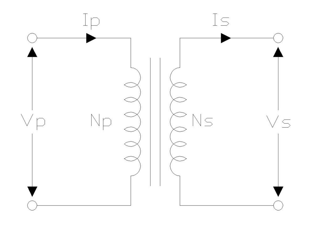
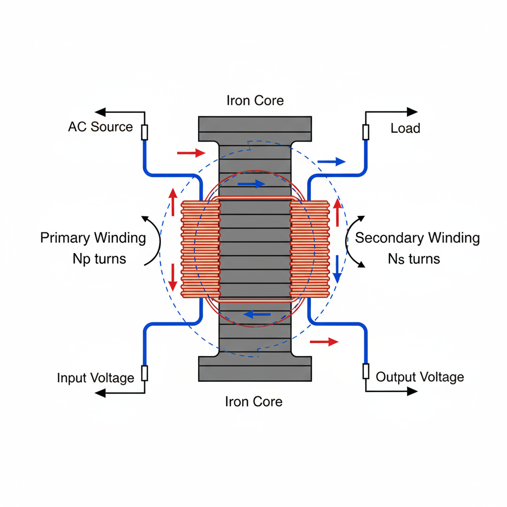
Transformer turns ratio is fundamental for electrical engineering students and professionals working with power systems. This ratio determines how voltage and current transform between the primary and secondary windings, making it one of the most critical parameters in transformer design and operation.
What is Transformer Turns Ratio?

The turns ratio of a transformer is defined as the ratio of the number of turns in the primary winding to the number of turns in the secondary winding. This seemingly simple parameter governs the voltage transformation capability of the transformer and forms the basis for understanding how these essential electrical devices operate.
Mathematically, the turns ratio is expressed as:
\( Turns \,Ratio = \frac{N_p}{N_s} \)
where \(N_p\)represents the number of turns in the primary winding and \(N_s\) represents the number of turns in the secondary winding.

The Fundamental Relationship
The beauty of transformer operation lies in the elegant relationship between turns ratio, voltage ratio, and current ratio. For an ideal transformer, these relationships are interconnected through the principle of electromagnetic induction.
The voltage ratio equals the turns ratio:
\( \frac{V_p}{V_s} = \frac{N_p}{N_s} \)
The current ratio is inversely proportional to the turns ratio:
\( \frac{I_p}{I_s} = \frac{N_s}{N_p} \)
This inverse relationship makes perfect physical sense: when voltage steps up, current steps down proportionally, maintaining power conservation in an ideal transformer.
Step-Up vs Step-Down Transformers
The turns ratio immediately tells you whether a transformer steps voltage up or down:
Step-Down Transformer: When \(N_p>N_s\), the turns ratio is greater than \(1\). The transformer reduces voltage from primary to secondary. For example, a turns ratio of \(5:1\) means the primary has five times more turns than the secondary, resulting in the secondary voltage being one-fifth of the primary voltage.
Step-Up Transformer: When \(N_p<N_s\), the turns ratio is less than \(1\). The transformer increases voltage from primary to secondary. A turns ratio of \(1:10\) indicates the secondary has ten times more turns, producing a secondary voltage ten times higher than the primary.
Calculating Turns Ratio: Worked Examples
Example 1: Finding Turns Ratio from Winding Turns
A transformer has 500 turns in its primary winding and 1000 turns in its secondary winding. Calculate the turns ratio.
Solution:
\( Turns \,Ratio = \frac{N_p}{N_s} = \frac{500}{1000} = \frac{1}{2} = 1:2 \)
This is a step-up transformer with a turns ratio of 1:2.
Example 2: Calculating Secondary Voltage
A transformer has 1000 turns on the primary winding and 200 turns on the secondary winding. If 250 V is applied to the primary, what is the secondary voltage?
Solution:
First, establish the turns ratio:
\( \frac{N_p}{N_s} = \frac{1000}{200} = 5:1 \)
Using the voltage relationship:
\( \frac{V_p}{V_s} = \frac{N_p}{N_s} \)
\( V_s = V_p \times \frac{N_s}{N_p} = 250 \times \frac{200}{1000} = 50 V \)
The secondary voltage is 50 V, confirming this is a step-down transformer.
Example 3: Finding Primary Turns
A transformer with an output voltage of 2200 V is supplied with 220 V at the primary. If the secondary winding has 2000 turns, calculate the number of turns in the primary winding.
Solution:
Using the voltage-turns relationship:
\( \frac{V_p}{V_s} = \frac{N_p}{N_s} \)
\( N_p = N_s \times \frac{V_p}{V_s} = 2000 \times \frac{220}{2200} = 200\, turns \)
The primary winding has 200 turns.
Example 4: Calculating Secondary Current
A step-down transformer has a turns ratio of 10:1. The primary winding has 1000 turns and draws a current of 2 A. What is the secondary current?
Solution:
Using the current relationship (inverse of turns ratio):
\( \frac{I_p}{I_s} = \frac{N_s}{N_p} \)
\( I_s = I_p \times \frac{N_p}{N_s} = 2 \times \frac{1000}{100} = 20 A \)
The secondary current is 20 A. Notice how the current increased as voltage decreased, maintaining power balance.
Example 5: Complete Transformer Analysis
A transformer has 600 turns on the primary and 120 turns on the secondary. 300 volts is applied to the primary and a current of 40 amps flows in the secondary. Calculate: (a) turns ratio, (b) secondary voltage, and (c) primary current.
Solution:
(a) Turns ratio:
\( \frac{N_p}{N_s} = \frac{600}{120} = 5:1 \)
(b) Secondary voltage:
\( V_s = V_p \times \frac{N_s}{N_p} = 300 \times \frac{120}{600} = 60 V \)
(c) Primary current:
\( I_p = I_s \times \frac{N_s}{N_p} = 40 \times \frac{120}{600} = 8 A \)
We can verify: Power in \(= 300 V × 8 A = 2400 W\), Power out \(= 60 V × 40 A = 2400 W\).
Practical Applications
Understanding turns ratio calculations is essential for various practical applications:
Power Distribution: Step-up transformers with turns ratios like 1:25 are used at power generation stations to increase voltage for efficient long-distance transmission, while step-down transformers reduce voltage for safe residential use.
Electronics and Chargers: Mobile phone chargers use step-down transformers with turns ratios of approximately 10:1 or higher to convert 120 V or 240 V AC mains to the low voltages required by electronic devices.
Isolation Transformers: Transformers with a 1:1 turns ratio provide electrical isolation between circuits while maintaining the same voltage level, crucial for safety in medical equipment and sensitive electronics.
Measuring Turns Ratio in Practice
While theoretical calculations use the number of turns, practical transformer turns ratio testing (TTR testing) measures the actual voltage ratio by applying a known voltage to the primary and measuring the induced voltage in the secondary under no-load conditions.
Modern TTR test equipment applies a low voltage (typically 8-10 V) to one winding and measures the output voltage, calculating the ratio with accuracy better than 0.1%. This testing is critical for:
- Verifying manufacturer specifications during commissioning
- Detecting shorted turns in windings
- Identifying tap changer problems
- Routine maintenance and preventive diagnostics
Real vs Ideal Transformers
In ideal transformers, the turns ratio exactly equals the voltage ratio. However, real transformers experience losses due to:
- Core losses: Hysteresis and eddy current losses in the magnetic core
- Copper losses: Resistive losses in the windings
- Leakage inductance: Not all magnetic flux links both windings
- Inter-winding capacitance: Capacitive effects at higher frequencies
These losses mean the actual voltage ratio may deviate slightly (typically less than 5%) from the theoretical turns ratio. This difference, known as ratio error, is why manufacturers often design transformers with slightly adjusted turns to compensate for these losses and achieve the desired voltage output.
Key Formulas Summary
For quick reference, here are the essential transformer turns ratio formulas:
Turns Ratio:
\( n = \frac{N_p}{N_s} \)
Voltage Relationship:
\( \frac{V_p}{V_s} = \frac{N_p}{N_s} = n \)
Current Relationship:
\( \frac{I_p}{I_s} = \frac{N_s}{N_p} = \frac{1}{n} \)
Power Conservation (Ideal Transformer):
\( V_p I_p = V_s I_s \)
Secondary Voltage:
\( V_s = V_p \times \frac{N_s}{N_p} \)
Secondary Current:
\( I_s = I_p \times \frac{N_p}{N_s} \)
Transformer Turns Ratio Calculator
Turns Ratio Calculator
Conclusion
Mastering transformer turns ratio calculations is essential for anyone working in electrical engineering. Whether you’re designing power systems, troubleshooting transformer issues, or simply trying to understand how voltage transformation works, the turns ratio provides the fundamental relationship that governs transformer behavior.