When a new overhead transmission line is constructed or after maintenance work is completed, it’s crucial to verify that all conductors are properly connected and in good working condition. The conductor continuity test is one of the most fundamental and important tests performed during transmission line commissioning and maintenance. This test ensures that each phase conductor (Red/R, Yellow/Y, and Blue/B phases) has continuous electrical contact throughout the entire line length and is not broken, corroded, or damaged at any point.
This blog post will walk you through the conductor continuity test procedures, help you understand what to look for, and provide real-world examples that you can apply to transmission line systems.
What is a Conductor Continuity Test?
A conductor continuity test is a non-destructive electrical test used to verify that:
- Each conductor is continuous from one end of the transmission line to the other
- Proper connections exist at all junctions, terminals, and mid-span joints
- No breaks, discontinuities, or high-resistance connections are present in the conductor
- Phase identification and marking are correct throughout the line
The test is typically performed after the insulation resistance test confirms no short circuits exist, and it ensures the mechanical and electrical integrity of the overhead line conductors before the line is energized.
Why is Conductor Continuity Test Important?
- Safety: Ensures no broken conductors that could fall and cause hazards
- Performance: Confirms that the line can carry the full rated current without excessive losses
- Reliability: Prevents unexpected outages due to conductor failures
- Quality Assurance: Validates proper installation and workmanship during line construction or maintenance
Prerequisites: Insulation Resistance Test First
Before conducting a continuity test, you must complete the insulation resistance test using a high-voltage insulation tester (typically 5kV or 10kV). The insulation test confirms:
- No short circuits between phases
- No earth faults between conductors and ground
- Proper insulation integrity of the line
Only when the insulation test results are satisfactory and show no evidence of short circuits should you proceed with the continuity test.
Important Note: Always ensure the transmission line is de-energized, isolated, and properly grounded before conducting any testing. Follow all safety procedures and use appropriate personal protective equipment (PPE).
Equipment Required for Conductor Continuity Test
To perform a proper conductor continuity test on a transmission line, you will need the following equipment:
| Equipment | Purpose | Notes |
|---|---|---|
| 5kV or 10kV Insulation Tester | To measure insulation resistance and perform continuity checks | Can measure very low resistance values (near zero ohms) |
| Multimeter (with continuity function) | Backup resistance measurement device | Useful for verification at lower voltage levels |
| Test Leads (high voltage rated) | To safely connect test equipment to line conductors | Must be properly insulated for the testing voltage |
| Ground Clamps | To establish proper reference ground at both ends | Ensures accurate measurements |
| Safety Equipment | PPE including gloves, helmet, arc-rated clothing | Essential for worker protection |
| Communication Equipment | Two-way radios or phones | For coordination between sending and receiving ends |
| Recording Sheet | To document all test results | Important for future reference and compliance |
Conductor Continuity Test Procedure
The conductor continuity test of a transmission line consists of two separate and complementary tests:
- Basic Continuity Test (to verify conductor continuity without phase consideration)
- Phase Marking Continuity Test (to verify correct phase identification and marking)
PART 1: Basic Conductor Continuity Test
This test verifies that each conductor is electrically continuous from the sending end to the receiving end of the transmission line.
Step 1: Prepare the Test Setup
- Ensure the transmission line is de-energized and properly isolated
- All ground switches should be in the OPEN position (disconnected)
- Establish clear communication between the sending end (test operator) and receiving end (assistant)
Step 2: Test Configuration for R-Phase Conductor
At the Sending End:
- CLOSE the R-Phase ground switch (connect R-Phase to ground)
- OPEN the Y-Phase and B-Phase ground switches
- All ground switches (GS) remain in open condition at receiving end
At the Receiving End:
- Connect the insulation tester to measure the insulation resistance between:
- R-Phase conductor and the reference ground (earth)
Step 3: Take Measurements
- Connect the insulation tester leads: one to the R-Phase conductor, one to ground
- The meter should show ZERO or LOW resistance
- If the reading is “HIGH” resistance, it indicates a break or severe corrosion in the conductor
Step 4: Repeat for Other Phases
Repeat the entire procedure for Y-Phase and B-Phase conductors:
- Close each respective phase ground switch at sending end
- Keep other phases open
- Record the resistance value at receiving end
Expected Results:
| Phase | Sending End Configuration | Receiving End Test | Expected Result |
|---|---|---|---|
| R-Phase | CLOSE R-Ph GS, OPEN Y-Ph GS, OPEN B-Ph GS | Test IR for R-Phase | Zero/Low |
| Y-Phase | OPEN R-Ph GS, CLOSE Y-Ph GS, OPEN B-Ph GS | Test IR for Y-Phase | Zero/Low |
| B-Phase | OPEN R-Ph GS, OPEN Y-Ph GS, CLOSE B-Ph GS | Test IR for B-Phase | Zero/Low |
PART 2: Phase Marking Continuity Test
This test verifies that the phase identification (phase marking or color coding) is correct throughout the transmission line. It ensures that the R, Y, and B phase markings correspond to the actual conductor positions.
Why Phase Marking is Important:
Incorrect phase marking can lead to:
- Improper three-phase motor operation (reverse rotation)
- Unbalanced loading on transformers
- Relay protection misalignment
- Difficulty in future maintenance and troubleshooting
Step-by-Step Procedure for Phase Marking Test:
Step 1: Connect Phases at Sending End (Create Test Circuit)
At the Sending End, connect two phases together while keeping the third phase isolated:
- Configuration 1: Connect R-Phase & Y-Phase together, OPEN B-Phase and all ground switches
- Configuration 2: Connect R-Phase & B-Phase together, OPEN Y-Phase and all ground switches
- Configuration 3: Connect Y-Phase & B-Phase together, OPEN R-Phase and all ground switches
Step 2: Measure Insulation Resistance Between Phases at Receiving End
At the Receiving End, measure the insulation resistance between the pairs of phases to verify the markings:
| Configuration | Sending End Connection | Receiving End IR Measurement | Expected Result |
|---|---|---|---|
| 1 | Connect R & Y Phase, Open B & all GS | Measure between R & Y at receiving end | Zero/Low |
| 1 (verification) | Connect R & Y Phase, Open B & all GS | Measure between B & R at receiving end | High |
| 1 (verification) | Connect R & Y Phase, Open B & all GS | Measure between B & Y at receiving end | High |
| 2 | Connect R & B Phase, Open Y & all GS | Measure between R & B at receiving end | Zero/Low |
| 2 (verification) | Connect R & B Phase, Open Y & all GS | Measure between Y & R at receiving end | High |
| 2 (verification) | Connect R & B Phase, Open Y & all GS | Measure between Y & B at receiving end | High |
| 3 | Connect Y & B Phase, Open R & all GS | Measure between Y & B at receiving end | Zero/Low |
| 3 (verification) | Connect Y & B Phase, Open R & all GS | Measure between R & Y at receiving end | High |
| 3 (verification) | Connect Y & B Phase, Open R & all GS | Measure between R & B at receiving end | High |
Step 3: Record All Results
Create a comprehensive test report documenting:
- Date and time of test
- Weather conditions
- Equipment used (model and serial number)
- All resistance measurements
- Phase identification confirmation
- Any anomalies or concerns
- Pass/Fail status
If all phase markings show continuity between connected phases and isolation between other phases, the phase marking test is PASSED.
Practical Example: 132 kV Transmission Line Continuity Test
Let’s walk through a real-world example of conducting a conductor continuity test on a 132 kV transmission line.
Scenario:
A new 132 kV, 50 km transmission line has just been completed. The line has three conductors (R, Y, B phases), each made of ACSR conductor. After the insulation test confirmed no short circuits, you are tasked with performing the conductor continuity test.
Test Execution:
Phase 1: Basic Continuity Test
- R-Phase Test: Close R-Phase ground switch at Sending End. Measure resistance from R-Phase to ground at Receiving End Tower (50 km away). Result: 0.002 ohms (PASS – shows R-Phase is continuous)
- Y-Phase Test: Close Y-Phase ground switch at Sending End. Measure resistance from Y-Phase to ground at Receiving End. Result: 0.003 ohms (PASS)
- B-Phase Test: Close B-Phase ground switch at Sending End. Measure resistance from B-Phase to ground at Receiving End. Result: 0.002 ohms (PASS)
Phase 2: Phase Marking Continuity Test
- R-Y Connection: Connect R & Y phases together at Sending End. Measure R-Y at Receiving End: 0.002 ohms (PASS – confirms R and Y are continuous and properly marked)
- R-B Connection: Connect R & B phases together at Sending End. Measure R-B at Receiving End: 0.003 ohms (PASS)
- Y-B Connection: Connect Y & B phases together at Sending End. Measure Y-B at Receiving End: 0.002 ohms (PASS)
Conclusion:
All tests passed with satisfactory results. The transmission line is ready for energization.
Transmission Line with Double Circuits
For higher voltage lines like 400 kV systems that often have double circuits (two separate transmission line circuits), the procedure is slightly more complex.
Additional Considerations:
- Double Circuit Configuration: Test each circuit separately, ensuring all switches of the non-test circuit are properly isolated
- Tower Footing Resistance: Must be low enough to provide proper grounding reference (typically < 10 ohms)
- Ambient Conditions: Temperature and humidity affect resistance measurements; document environmental conditions
- Test Voltage Selection: Use 10 kV test voltage for higher voltage systems to obtain more reliable measurements
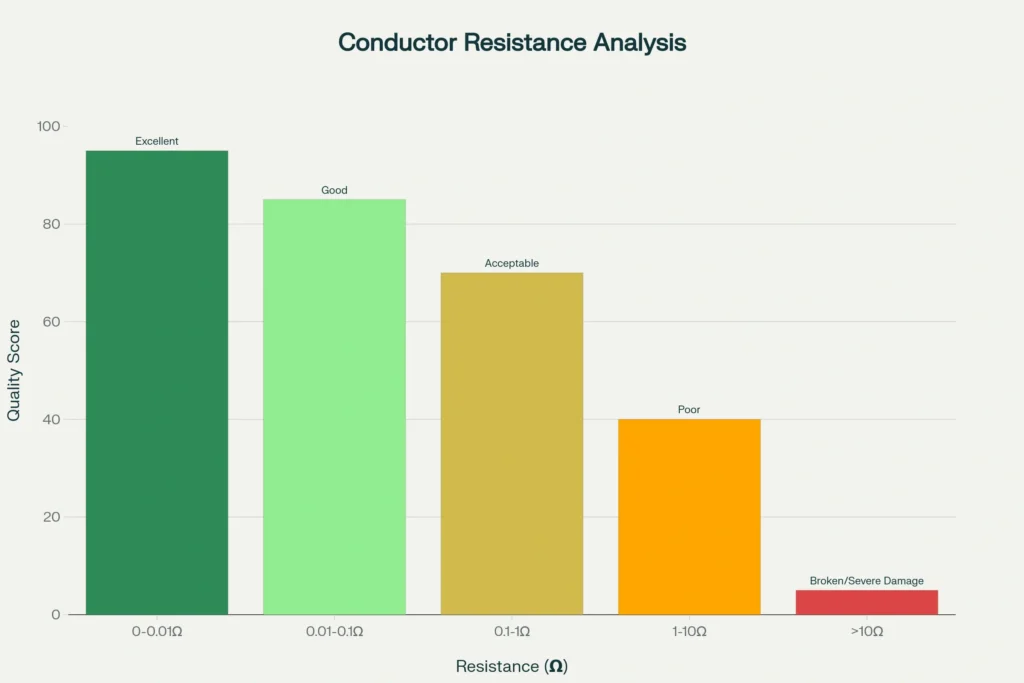
Resistance Values and What They Indicate
| Resistance Reading | Indication | Possible Causes | Action Required |
|---|---|---|---|
| 0-0.01 Ω | Excellent (Continuous) | Good conductor connection | Continue with commissioning |
| 0.01-0.1 Ω | Good | Acceptable resistance for long lines | Continue with commissioning |
| 0.1-1 Ω | Acceptable but monitor | Higher than ideal; may indicate oxidation | Document and monitor |
| 1-10 Ω | Poor continuity | Corrosion, loose connections, or damaged conductor | Investigate and repair |
| >10 Ω or “High” | Broken or severe damage | Open circuit, break in conductor, corroded joint | Stop testing and investigate |
Safety Precautions During Conductor Continuity Testing
- De-energize the Line Completely: Use lockout/tagout procedures to ensure the line cannot be accidentally energized
- Verify Absence of Voltage: Use a non-contact high-voltage detector to confirm the line is not live
- Proper Grounding: Ground the test leads and transmission line adequately to prevent electrical hazards
- Two-Person Operation: Always have at least two trained personnel – one at sending end, one at receiving end – with clear communication
- Weather Considerations: Avoid testing during lightning or heavy rainfall; moisture can affect readings
- Personal Protective Equipment: Wear arc-rated clothing, safety helmet, insulated gloves, and safety boots
- Test Equipment Calibration: Verify that the insulation tester is calibrated and functioning properly before use
Frequently Asked Questions
A: No. The insulation test must be completed first to confirm there are no short circuits. Attempting continuity testing with short circuits could produce misleading results or damage the testing equipment.
A: Use a 5kV to 10kV insulation tester. For 132 kV systems, a 5kV tester is typically sufficient, while 10kV testers provide more reliable measurements on longer transmission lines.
A: A well-maintained ACSR conductor can be tested for continuity over distances exceeding 50 km and still show very low resistance (typically 0.001-0.01 ohms per km depending on conductor size and temperature).
A: A “High” reading indicates the conductor is either broken, severely corroded, or has a high-resistance joint. This requires investigation and repair before the line can be energized.
A: No. Each phase must be tested individually to ensure accuracy and proper phase identification. Simultaneous testing of multiple phases will produce unreliable results.
A: During commissioning (before energization), after major maintenance, and periodically (typically every 3-5 years) as part of preventive maintenance programs. More frequent testing may be needed in corrosive environments.
Conclusion
The conductor continuity test is an essential quality assurance procedure for transmission line commissioning and maintenance. By following the systematic procedures outlined in this guide, engineers and technicians can ensure that overhead line conductors are properly connected, correctly identified, and ready for safe operation.
Remember: Thorough testing during commissioning prevents costly outages and safety hazards during operation. Always prioritize safety, maintain detailed records, and follow industry standards and local regulations applicable to your region.