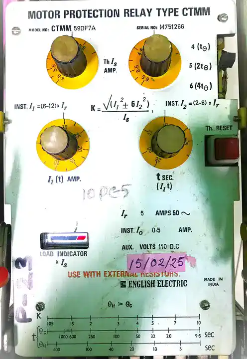
The Comprehensive Thermal Motor Manager (CTMM) relay protects three-phase induction motors from electrical faults and thermal stress. The CTMM integrates various independent protection functions including instantaneous phase overcurrent, Instantaneous negative sequence overcurrent, instantaneous earth fault, motor stall detection, and thermal overload (based on first-order thermal modeling). These protection functions operates in parallel with individually configurable thresholds and response characteristics.
Unlike electromechanical relays that respond to single fault parameters, the CTMM relay analyzes multiple electrical measurements simultaneously: three-phase currents, residual current, and calculated symmetrical components. This multi-parameter approach enables the relay to distinguish between normal motor starting transients and genuine fault conditions.
Why Multiple Protection Functions?
A single protection function cannot address all motor failure modes:
- Short circuits require instantaneous response (milliseconds) or the arc will damage the motor beyond repair
- Overloads require time delay so brief starting current doesn’t trip the protection
- Ground faults need sensitivity down to single-digit amperes to catch insulation deterioration early
- Voltage imbalance creates rotor heating that won’t show as high phase current
- Motor stall needs detection before thermal damage occurs when the motor cannot rotate
The CTMM relay handles all scenarios with appropriate response characteristics.
1. Instantaneous Over Current Protection (Phase)
When motor phase current exceeds a programmed threshold \((I_inst)\), the relay trips immediately—without waiting. This protects against three-phase bolted short circuits that would melt motor windings within seconds if allowed to continue.
Setting the Pickup Value
The pickup must sit in a narrow window:
- Too low → Motor inrush current during starting triggers false trips
- Too high → Short circuits escalate before the relay responds
A 10 kW motor with 18 A rated full-load current (FLC) might have starting inrush of 90-144 A (5-8× FLC). The instantaneous pickup might be set at 180 A (10× FLC) to allow starting while catching real short circuits.
Real-World Example
Consider a 15 kW motor in a conveyor system:
| Condition | Phase Current | Relay Action |
|---|---|---|
| Normal running | 28 A | No trip |
| Motor starting | 120 A | No trip (below 150 A setting) |
| Phase-to-phase short circuit | 280 A | Trip in 20-50 ms |
| Three-phase short circuit | 350 A | Trip in 20-50 ms |
The relay measures current every 5-10 milliseconds, so it detects faults almost immediately.
The instantaneous element must also coordinate with upstream protection. If a 100 A main breaker protects the motor circuit, the CTMM instantaneous setting should be set low enough that it responds before the main breaker nuisance trips from normal inrush.
2. Motor Stall Protection
Motor stall occurs when the motor draws current but cannot rotate or rotates much slower than normal. The motor is mechanically blocked or held from rotating by external load or friction. During stall, the motor acts similar to a transformer secondary winding connected to a short circuit and high current flows through windings that cannot dissipate heat through normal ventilation because the rotor isn’t moving.
Common causes of motor stall:
- Conveyor jam – Object stuck on conveyor belt preventing rotation
- Mechanical blockage – Bearing failure, misalignment, or seized gearbox
- Belt failure – Belt broken or slipped off pulleys
- Coupling failure – Shaft coupling broken or misaligned
- Centrifugal pump cavitation – Pump cannot prime, impeller blocked
- Overloaded fan – Blade hitting shroud or accumulation of debris
Why Stall is Dangerous
When a motor stalls, the rotor winding experiences extreme heating:
- Normal running at full load: Motor ventilation removes heat efficiently
- Motor stall: Rotor is stationary, so cooling air doesn’t move through motor
- Current remains high (200-400% of FLC) but cannot be expelled as mechanical output
- Result: Motor winding temperature can reach 200°C+ within 10-30 seconds
Unlike a brief starting transient (which lasts 2-3 seconds), a stalled motor maintains high current indefinitely until power is removed. Without stall protection, the motor insulation will fail causing:
- Winding meltdown and permanent motor damage
- Phase-to-ground arc that energizes motor frame
- Fire risk from overheating
- Production line shutdown
Stall Detection Methods
The CTMM relay can detect stall in several ways:
Method 1: Current + Time (Simple Stall Detection)
If current exceeds a threshold (typically 150-200% FLC) for a time period longer than normal starting (typically 5-10 seconds), the relay concludes the motor is stalled.
Example: Motor rated 30 A
- Stall pickup: 150 A (5× FLC = 150 A)
- Stall time delay: 8 seconds
- Normal starting time: 3 seconds
If the motor draws 150 A for more than 8 seconds without returning to normal running current, stall protection trips.
Method 2: Slip Detection (Advanced)
Some CTMM relays calculate motor slip by analyzing current frequency characteristics. Slip is the difference between supply frequency and rotor frequency. A normal running motor at 50 Hz supply has slip of 2-5%. A stalled motor has 100% slip (rotor not turning at all).
The relay can estimate slip and trip if slip exceeds 90% for the preset time delay.
Method 3: Load Profile Recognition
Advanced CTMM relays learn the normal load profile of the motor. If the motor operates at unusually high current for an extended period that doesn’t match the normal startup profile, the relay triggers stall protection.
Stall Protection Coordination with Thermal
Motor stall protection and thermal protection work together:
- Stall protection acts as the primary line of defense, responding within 8-10 seconds to prevent damage
- Thermal protection provides backup, monitoring temperature continuously and responding if stall is missed or delayed
Example for 22 kW motor:
| Time | Current | Thermal Calc | Stall Timer | Action |
|---|---|---|---|---|
| 0 sec | 45 A (normal) | 65°C | 0 (reset) | Running normally |
| 2 sec | 150 A (jam) | 68°C | 2 sec counting | Motor blocked, stall timer active |
| 5 sec | 150 A (jam) | 85°C | 5 sec counting | Continuing to rise |
| 8 sec | 150 A (jam) | 105°C | 8 sec = TRIP | Stall protection trips |
If stall protection had not triggered, thermal protection would trip at approximately 12-13 seconds when temperature reaches 130°C.
Stall Protection Pickup Settings
The stall protection pickup must be set carefully:
- Too high – Motor stalls for extended period before protection responds, allowing thermal damage
- Too low – Brief current spikes during normal transients trigger false trips
Typical recommendations by motor size:
| Motor Size | Stall Pickup (% FLC) | Stall Time Delay |
|---|---|---|
| < 5 kW | 180-200% | 5-8 seconds |
| 5-30 kW | 150-180% | 8-12 seconds |
| 30-100 kW | 150-160% | 10-15 seconds |
| > 100 kW | 140-150% | 12-20 seconds |
Larger motors can tolerate stall current for slightly longer periods before insulation damage begins, so time delays are extended.
Stall Protection vs. Instantaneous Overcurrent
These two functions operate differently:
| Parameter | Instantaneous OC | Stall Protection |
|---|---|---|
| Trigger | Any phase current exceeds pickup | Current exceeds pickup AND duration exceeds timer |
| Typical Pickup | 200-300% FLC | 150-180% FLC |
| Response | Milliseconds | 5-20 seconds |
| Purpose | Protect against short circuits | Protect against locked rotor |
| False Trip Risk | Low (only responds to extreme current) | Higher if time delay too short |
Commissioning Stall Protection
When setting up stall protection:
- Determine normal starting current: Measure actual motor inrush with clamp meter during cold start
- Determine normal starting time: How long does the motor take to accelerate to full speed (typically 2-5 seconds for most motors)
- Set stall pickup 30-50% above normal running current but below short-circuit current
- Set stall time delay 2-3 seconds longer than normal starting time
- Test commissioning:
- Start motor and verify it reaches full speed within the stall time delay without tripping
- If available, artificially block motor load and verify stall protection trips
Example test for 11 kW motor:
- Motor rated current: 22 A
- Measured starting inrush: 105 A
- Normal acceleration time to full speed: 4 seconds
- Stall pickup setting: 160 A (7.3× FLC)
- Stall time delay setting: 6 seconds
Test 1: Normal start
- Confirm motor reaches full speed within 6 seconds
- Current drops to 22 A before time delay expires
- Result: No trip (expected)
Test 2: Artificial stall (if testable)
- Block motor load mechanically
- Current rises to 160 A
- Relay counts 6 seconds
- After 6 seconds at high current
- Result: Trip occurs (expected)
Instantaneous Over Current Protection (Negative Sequence)
When a three-phase power system has unbalanced voltages or unbalanced loading, the current pattern becomes unbalanced. Using a mathematical technique called symmetrical component decomposition, engineers break unbalanced currents into three rotating patterns:
- Positive sequence – Rotates forward, normal operation
- Negative sequence – Rotates backward, creates heating
- Zero sequence – Same phase in all three wires, indicates ground fault
The negative sequence current rotates opposite to motor rotation, inducing double-frequency currents in the rotor. These rotor currents generate heat at twice the normal rate, causing rapid temperature rise.
Typical Voltage Unbalance Causes
Common industrial situations that create voltage unbalance:
- Single-phase load on one phase of a three-phase panel
- Loose transformer connection feeding the motor
- Transmission line carrying unequal loads
- Distribution feeder with unequal cable impedances
- Welding equipment drawing single-phase current from the distribution
Protection Function Operation
The CTMM relay calculates negative sequence current using the three measured phase currents. A 30 A motor might trip on sustained negative sequence current of 2-3 A (7-10% of rated current).
The protection uses time delay rather than instantaneous response because brief voltage sags and transients create temporary negative sequence. The relay typically waits 5-10 seconds before tripping to allow the power system to stabilize.
Practical Example
A 22 kW motor feeding a hydraulic pump experiences voltage imbalance when a large welder starts nearby:
| Event | Phase A | Phase B | Phase C | Neg Seq | Action |
|---|---|---|---|---|---|
| Normal | 42 A | 42 A | 41 A | 0.3 A | None |
| Welder starts | 44 A | 38 A | 40 A | 3.2 A | Timer starts |
| Welder stops | 42 A | 42 A | 41 A | 0.3 A | Timer resets |
| Sustained imbalance | 50 A | 30 A | 40 A | 8 A | Trip after 5 sec |
In the first three scenarios, the unbalance is temporary so no trip occurs. In the last scenario, continuous unbalance causes the timer to count down to zero.
Motor Damage Risk from Negative Sequence
A motor can tolerate negative sequence for brief periods. The damage threshold depends on the motor design:
- Up to 2-3% negative sequence – No issue even for continuous operation
- 3-10% negative sequence – Acceptable for a few minutes during transients
- Above 10% negative sequence – Risk of rotor damage within hours
Instantaneous Earth Fault Protection
Motor insulation deteriorates from heat, moisture, mechanical stress, and contamination. When insulation fails, current flows from the energized conductor through the defect to ground. The relay must detect this fault current before arcing destroys the motor or creates a shock hazard.
The relay monitors residual current, the vector sum of all three phase currents. In a healthy motor, residual current is nearly zero. When insulation fails, residual current appears.
Sensitivity Levels
The CTMM relay offers two earth fault settings:
Instantaneous Earth Fault (I₀_inst) – High-sensitivity setting for rapid response to arcing faults
- Typical pickup: 20-50% of motor rated current
- Response time: 20-100 milliseconds
- Protects against high-impedance faults that arc
Time-Delayed Earth Fault – Lower sensitivity for early warning of degrading insulation
- Typical pickup: 10-20% of motor rated current
- Response time: 10-20 seconds (inverse time characteristic)
- Protects against insulation aging
Earth Fault Current Calculation
The relay sums the three phase currents:
\(I₀ = |I_A + I_B + I_C|\)
In a three-phase system, the three currents normally sum to near zero. Any residual indicates either a ground fault or a leakage path.
Testing Earth Fault Protection
During commissioning, technicians inject small currents through the residual current transformer to verify protection operates:
- Inject 30% of rated current residual → Relay should NOT trip (below setting)
- Inject 50% of rated current residual → Relay should trip within instantaneous time
- Reduce current to 15% of rated → Relay time-delayed element should start counting
This testing confirms the protection can detect real ground faults.
Thermal Protection
Motor insulation has maximum safe temperature. Operating above this temperature accelerates insulation degradation and shortens motor life:
- Class B insulation – 130°C maximum (used in ~60% of industrial motors)
- Class F insulation – 155°C maximum (more robust)
- Class H insulation – 180°C maximum (premium motors)
Current flowing through motor resistance generates heat. Higher current = faster temperature rise.
Cold Curve
The cold curve assumes the motor starts from ambient temperature (20-30°C) with the full available temperature rise before reaching the dangerous limit. This applies when:
- Motor has been idle overnight or longer
- Motor just started from cold condition
- First motor start in morning shift
The cold curve is the most permissive protection because the motor has time before overheating.
Cold Curve Example: Motor Winch
A 5.5 kW motor lifts a load. The cold curve allows this operation:
- Motor rated 11 A at full load
- Cold curve at 22 A (2× FLC) → allows ~30 minutes
- Cold curve at 33 A (3× FLC) → allows ~8 minutes
- Cold curve at 50 A (4.5× FLC) → allows ~2 minutes
This flexibility is critical. Without the time delay, starting inrush (which might reach 6-8× FLC) would trigger a trip before the motor even started running.
Thermal Time Constant Parameter
The thermal time constant (t_θ) represents how fast the motor temperature responds to current changes. A larger time constant means slower temperature rise:
- Small motor (< 5 kW): t_θ ≈ 10-15 minutes
- Medium motor (10-50 kW): t_θ ≈ 20-40 minutes
- Large motor (> 100 kW): t_θ ≈ 35-60 minutes
The time constant depends on motor size, cooling method, and design. A critically cooled motor (using high velocity air cooling) has a smaller time constant than a naturally cooled motor.
The CTMM relay uses the time constant to calculate how current at time X will raise temperature at time Y.
Hot Curve
The hot curve assumes the motor is already warm from previous operation, starting from approximately 80°C. This represents:
- Motor running continuously near rated load
- Motor that was recently shut down
- Motor in a hot ambient environment (summer, near furnaces)
At the start of hot curve operation, only 50°C margin remains before the 130°C limit (for Class B). This smaller margin means the protection must trip faster.
Hot Curve vs. Cold Curve Comparison
Same motor, same overload current, different starting temperatures:
| Current | Starting Temp | Margin to Max | Time to Trip |
|---|---|---|---|
| 150% FLC (cold start) | 20°C | 110°C | 35 minutes |
| 150% FLC (hot motor) | 80°C | 50°C | 16 minutes |
The motor running hot already used up much of its temperature capacity, so the protection responds roughly twice as fast.
Thermal Protection Parameters
The K Parameter (Thermal Constant)
The K parameter determines how much temperature rise occurs per unit of current squared. Higher K = faster heating = quicker trip at a given current.
The K parameter depends on:
- Motor resistance – How much I²R loss in windings
- Thermal capacity – How much material to heat up
- Cooling method – How efficiently heat dissipates
Calculation:
\(K = \frac{(Temperature rise at rated load)}{(1² × thermal time constant)}\)
Example: A 22 kW motor shows 45°C rise at rated current with 30-minute time constant:
\(K = \frac{45}{(1² × 30 × 60)} = \frac{45}{1800} = 0.025 °C/sec per amp²\)
This means each ampere of current squared contributes 0.025°C/sec of heating.
Example: Complete CTMM Protection in Action
A 30 kW motor with configured CTMM settings:
Protection Settings:
- Instantaneous phase OC: 180 A
- Stall detection: 160 A pickup, 8-second delay
- Negative sequence: 5 A pickup, 5-second delay
- Earth fault instantaneous: 25 A
- Earth fault time delay: 8 A, 10-second delay
- Thermal time constant: 25 minutes
- K parameter: 0.032
- Maximum temperature: 130°C (Class B)
Scenario 1: Motor Starting Normally
- Starting inrush: 110 A
- Duration: 3 seconds
- Instantaneous OC: Not exceeded (below 180 A) → No action
- Stall detection: 110 A is below 160 A setting → No action
- Thermal: Cold curve allows 110 A for 40+ minutes → No action
- Result: Motor starts successfully
Scenario 2: Locked Rotor (Mechanical Jam)
- Sustained current: 200 A
- Duration: 8 seconds
- Instantaneous OC: Exceeded (200 > 180 A) → Trip in 40 ms
- Stall: Would also trip if instantaneous did not act first
- Result: Motor disconnected before rotor burns out
Scenario 3: Motor Stall – Subtle Blockage
- Current: 165 A (just above stall pickup)
- Duration: Sustained
- Instantaneous OC: Not exceeded (165 < 180 A) → No action (allows stall detection to work)
- Stall detection: 165 A exceeds 160 A pickup, timer starts counting
- At 8 seconds: Stall protection trips
- Result: Motor protected from thermal damage
Scenario 4: Overload
- Sustained current: 45 A (150% FLC)
- Motor temperature rising steadily
- Hour 1: Temperature reaches 60°C (cold curve)
- Hour 2: Temperature reaches 85°C (transitioning to hot curve)
- Hour 3: Temperature reaches 115°C and still rising
- Hour 3:45: Calculated temperature reaches 130°C
- Result: Thermal protection trips, motor disconnected before insulation damage
Scenario 5: Voltage Unbalance
- Phase A: 48 A
- Phase B: 38 A
- Phase C: 40 A
- Negative sequence current: 4.5 A
- Unbalance duration: 8 seconds (welder in operation)
- Negative sequence: 5-second timer activated at 4.5 A
- Unbalance stops at 8 seconds
- Result: No trip (timer reset before reaching zero), motor unharmed
Scenario 6: Insulation Failure
- Residual current: 18 A (gradually increasing over days)
- Duration: Sustained
- Instantaneous earth fault: 25 A setting not reached
- Time-delayed earth fault: 8 A setting exceeded at 18 A
- Result: Trip after 10 seconds, motor disconnected before arcing damage
Advantages and Limitations
Advantages of CTMM Protection
- Multi-parameter monitoring – Catches faults other relays miss
- Motor stall detection – Prevents motor damage from locked rotor
- Thermal model – Allows starting while protecting against overload
- Flexibility – Settings adjust for each motor’s characteristics
- Diagnostic capability – Records when and why it tripped
- Communication – Modern relays send data to SCADA or energy management systems
Limitations to Consider
- Requires accurate data – Protection only works well if motor parameters are correct
- Commissioning time – Setting up all functions takes more effort than basic protection
- Cost – CTMM relays cost 3-5× more than simple overload relays
- Expertise needed – Requires trained technician for settings and testing
- False stall trips – If time delay set too short, transient overloads can trigger stall protection
Conclusion
The CTMM relay provides protection that matches the real thermal and electrical characteristics of three-phase motors. By combining instantaneous overcurrent detection, motor stall protection, negative sequence monitoring, ground fault sensing, and advanced thermal modeling, the CTMM allows motors to start and operate while still providing rapid response to dangerous fault conditions.
Proper commissioning with accurate motor data ensures the motor receives protection it can trust. Motor stall protection is particularly critical in applications with mechanical load risk, preventing motor damage and production downtime when blockages or mechanical failures occur.