A Current Transformer, commonly abbreviated as CT, is a specialized type of instrument transformer designed to measure high alternating currents safely and accurately. Unlike power transformers that step voltage up or down, current transformers step down current to manageable levels that can be measured by standard instruments. The fundamental purpose of a CT is to produce a reduced current in its secondary winding that is proportional to the current flowing in its primary winding. This makes it possible to measure currents that would otherwise be too dangerous or impractical to measure directly.
In modern electrical power systems, current transformers serve as the eyes and ears of metering and protection schemes. They enable utility companies to bill customers accurately, help engineers monitor system performance, and provide information to protective relays that safeguard expensive equipment from damage. Without current transformers, managing today’s high-voltage, high-current electrical networks would be impossible.
1. Working Principle of Current Transformers
The working principle of a current transformer is based on Faraday’s law of electromagnetic induction. When alternating current flows through the primary conductor, it creates a time varying magnetic flux in the CT’s magnetic core. This changing flux induces a proportional voltage in the secondary winding according to the turns ratio.
If a CT has a turns ratio of 1000:5, it means that 1000 amperes in the primary will produce 5 amperes in the secondary with a transformation ratio of 200:1.
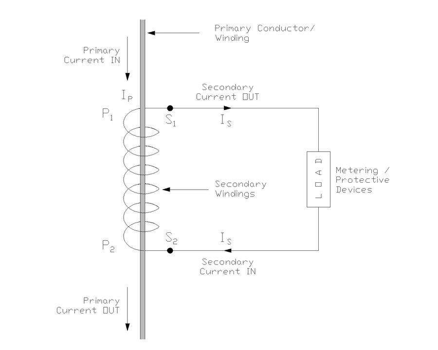
Looking at the above diagram, you can see the typical CT configuration. The primary conductor carrying the main load current passes through the CT core which may have one turn. The secondary winding consists of many turns wound around the magnetic core. When primary current flows, it creates magnetic flux that links with the secondary winding, inducing a voltage in secondary winding which in turn creates a secondary current when connected to load or shorted. The secondary current flows through connected metering or protective devices, which could be energy meters, ammeters, or protective relays as shown in the load box in the diagram.
What makes a CT unique is that it operates with its secondary winding connected to a very low impedance load essentially working under near short-circuit conditions. This is fundamentally different from voltage transformers. The secondary burden which is the total impedance of connected instruments and wiring should be kept within specified limits to maintain accuracy and safety.
2. Types of Current Transformers for Different Applications
Current transformers come in various physical configurations to suit different installation requirements and voltage levels.
- The wound type CT has both primary and secondary windings wound on a magnetic core. This types of CT’s are typically used where the primary current is relatively low.
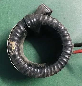
- The bar type CT features a single straight conductor as the primary passing through the center of a toroidal core with secondary windings. This design is common in medium voltage applications and offers good accuracy with compact size.
- Window type or through-type CTs have no primary winding at all. Instead, the primary conductor simply passes through a window in the CT core, with the secondary winding surrounding the core. This design provides easy installation on existing bus bars or cables without breaking the circuit.
- Split-core CTs take this convenience further by allowing the core to be opened and clamped around a conductor without any disconnection, making them ideal for retrofitting or temporary measurements.
3. CT Classes: Metering and Protection
Current transformers are broadly classified into metering class and protection class CTs. Each of them designed with different performance characteristics that suit their specific purposes. The classification determines how the CT behaves under normal and fault conditions.
3.1 Metering Class Current Transformers
Metering class CTs are designed to provide high accuracy under normal operating conditions, typically from 5% to 120% of rated current. Their primary job is to ensure that energy meters and measuring instruments receive an accurate representation of the load current for billing and monitoring purposes.
Common accuracy classes for metering CTs include 0.2, 0.5, and 1.0, where the number represents the maximum percentage error at rated current.
The important characteristic of metering CTs is that they are designed to saturate when the current exceeds about 120-150% of their rated value. This saturation protects connected meters from damage during fault conditions.
For example, if a short circuit occurs and current shoots up to 20 times normal, a metering CT will saturate, limiting the secondary current to safe levels. This prevents the moving parts in energy meters from being damaged by excessive current.
Consider a practical example: A 400:5A metering class 0.5 CT installed on a feeder that normally carries 350A. Under normal conditions, the CT produces 4.375A secondary current with an error within ±0.5%. If a fault occurs and current jumps to 8000A, the CT saturates and secondary current might only reach 10-15A instead of the proportional 100A. This protects the connected meter.
3.2 Protection Class Current Transformers
Protection class CTs serve an entirely different purpose. They must accurately reproduce high fault currents without saturation so that protective relays receive correct information to operate during abnormal conditions. These CTs are designed to maintain accuracy even when primary current reaches 20 to 30 times the rated value.
Common protection classes include 5P, 10P, and PS (or PX) class.
The designation 5P20 means the CT will maintain accuracy within 5% at 20 times the rated current. The knee point of the magnetization curve is much higher in protection CTs compared to metering CTs. This ensures that during severe faults, when primary current might reach thousands of amperes, the secondary current remains proportional enough for relays to calculate the fault magnitude and location accurately.
Let’s understand this with a real-world scenario: A 33kV substation has a 600:1A protection class 5P20 CT protecting a transformer. Under normal conditions with 500A load, everything operates smoothly. When an internal transformer fault occurs the primary current spikes to 15,000A. The protection CT accurately reproduces this as 25A in the secondary (accounting for the 600:1 ratio). This allows the differential relay to detect the fault and trip the circuit breaker within milliseconds.
4. CT Burden and Its Importance
The term “burden” in CT terminology refers to the total impedance connected to the secondary winding, including instruments, relays, and connecting wire resistance. Burden is typically expressed in volt-amperes (VA) at a specific power factor. The burden significantly affects CT performance, and exceeding the rated burden can lead to increased errors and safety hazards.
Every instrument connected to a CT secondary contributes to the burden. An ammeter might add 2VA, a wattmeter 2.5VA, protective relays another 5VA, and cable resistance could contribute 1-2VA depending on length.
When selecting a CT, you must calculate the total expected burden and choose a CT with adequate burden capacity. For instance, if your total burden is 12VA, selecting a CT rated for 15VA provides a safety margin.
Excessive burden causes increased secondary voltage drop, which can lead to CT saturation even at normal currents. This is particularly problematic for protection CTs as premature saturation prevent relays from detecting faults correctly. Additionally, high burden increases CT temperature, reducing insulation life and causing failures.
5. Current Transformer Knee Point
The knee point voltage is a specification for protection class current transformers. Knee point voltage represents the voltage at which the magnetization curve starts to bend sharply. At the knee point voltage, the current transformer (CT) begins to saturate. At this point, a 10% increase in secondary voltage causes a 50% increase in magnetizing current, indicating the onset of core saturation.
For instance, a CT with a knee point of 150V can accurately reproduce fault currents as long as the voltage across the secondary burden doesn’t exceed this value.
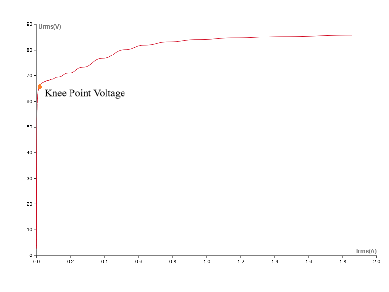
As shown in the above magnetizing curve plot, before knee point (to the left), a large increase in voltage requires only a tiny increase in current, meaning the CT is working efficiently and linearly.
At the knee point (marked by the red dot), the curve bends sharply. After this point (to the right), even a small increase in voltage requires a huge increase in magnetizing current. This means the CT stops transforming current accurately and starts diverting most of the primary current into magnetizing the core instead of sending it to the secondary output.
When selecting protection CTs, the knee point must be significantly higher than the maximum expected secondary voltage during fault conditions. This ensures the CT remains in its linear operating region and provides accurate current transformation to protective relays.
The knee point value is determined through testing by applying increasing voltage to the secondary while measuring magnetizing current with the primary open-circuited. Higher knee point values generally indicate better performance during severe fault conditions but come with increased cost and size.
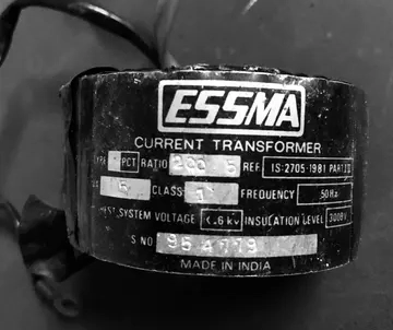
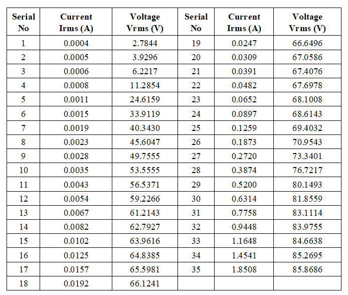
You can check the following Knee Point Voltage data of a 132 kV CT which I tested very recently.
6. CT Polarity and Connection Conventions
Polarity in current transformers determines the relative direction of instantaneous currents in primary and secondary windings. Proper polarity is important for correct metering and protection schemes.
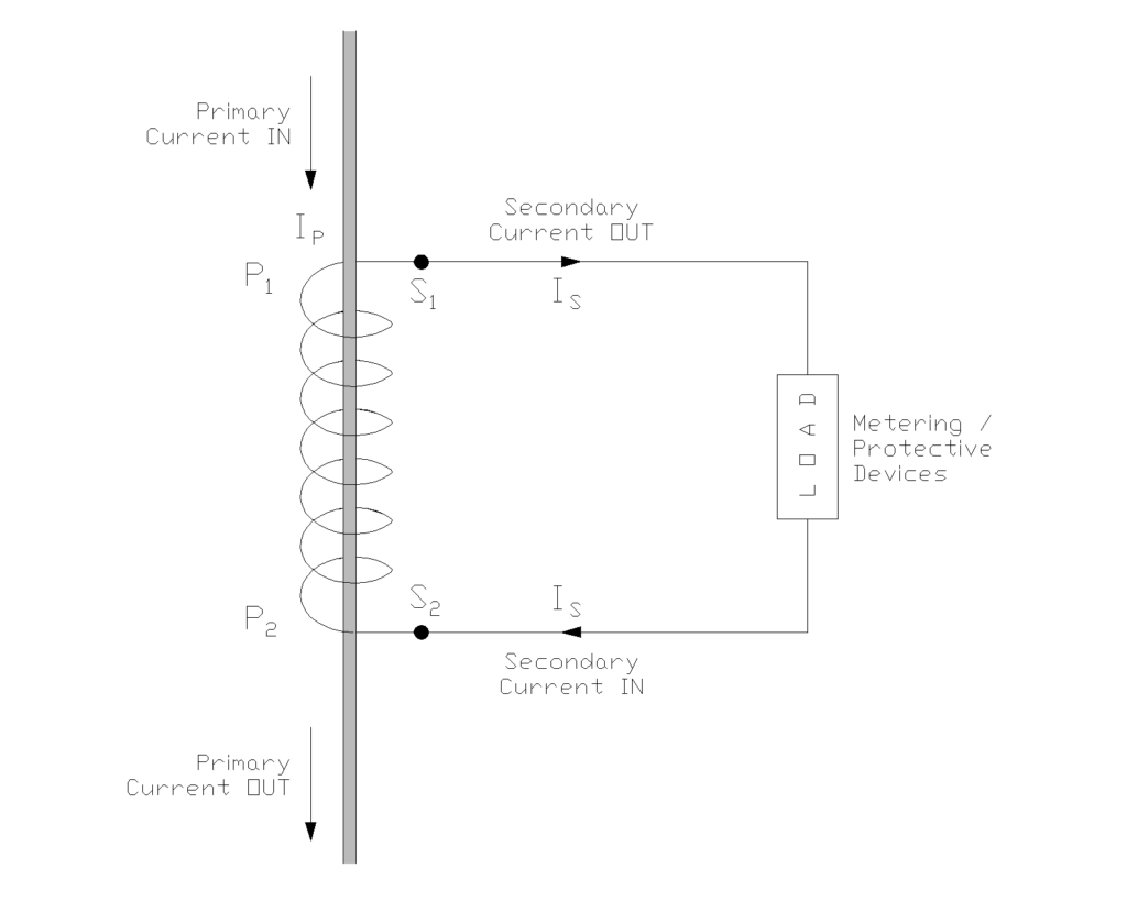
CT terminals are marked with polarity designations, typically P1, P2 for primary and S1, S2 for secondary. When current enters P1, it exits P2 in the primary, and simultaneously, current exits S1 and enters S2 in the secondary as shown in the above diagram.
Incorrect polarity connections in metering applications might show negative power or incorrect energy readings.
In protection schemes, wrong polarity can be catastrophic. Consider a differential protection scheme where two CTs compare current entering and leaving a transformer. If one CT is connected with reversed polarity, the relay sees a false differential current even under normal conditions which causes nuisance tripping. Conversely, during an actual internal fault, the relay might not detect it at all.
The diagram shows the standard polarity marking convention. Notice how the primary current flows from top to bottom through the primary conductor, and the secondary current flows outward from S1 to the connected load and returns to S2. This polarity relationship must be maintained during installation to ensure proper operation of connected metering and protective devices.
7. CT Ratio and Selection Criteria
The CT ratio is the relationship between primary and secondary currents. Common secondary ratings are 1A or 5A, with 5A being more prevalent in North America and 1A in Europe and many other regions.
The primary rating is selected based on the maximum expected load current. For example, if a feeder carries a maximum of 800A, you might select a 1000:5A CT to provide some headroom.
Selecting the appropriate CT ratio involves several considerations beyond just the maximum current. You need to ensure that under minimum load conditions, the secondary current is high enough for accurate measurement, typically not less than 10% of rated secondary current. For protection applications, the CT should not saturate at the maximum expected fault current. For metering applications, you want good accuracy across the normal operating range without excessive oversizing.
Here’s a practical example of ratio selection: A 11kV motor feeder normally operates at 50A but can handle up to 80A during starting. Expected fault current is 5000A. For metering, you might select a 100:5A CT (ratio 20:1) which keeps the secondary current between 2.5A (at 50A) and 4A (at 80A), providing good accuracy. For protection, you’d need a 100:1A or 200:1A CT with class 5P20 or higher to handle the 5000A fault current without saturation.
8. CT Testing and Commissioning
Before putting a new CT into service, several tests verify proper installation and performance.
The polarity test confirms that terminals are correctly marked and connected. This can be done using a simple DC battery and galvanometer method or with specialized CT testing equipment. You connect a battery momentarily to the secondary while observing the galvanometer on the primary side. The needle deflection direction indicates the polarity relationship.
Insulation resistance testing, performed with a megger, ensures that the CT windings are not damaged and properly insulated from the core and ground. Typical insulation resistance values should be above 1000 megohms for new CTs, though aged CTs might show lower values that are still acceptable. The test voltage depends on the CT voltage rating, typically 1000V for low voltage CTs and 5000V for high voltage units.
Ratio verification ensures the CT provides the correct transformation ratio. This involves injecting a known primary current and measuring the resulting secondary current. For example, injecting 100A primary should produce 5A secondary in a 100:5A CT.
Modern CT test sets can perform tests including ratio, polarity, burden, and excitation characteristics in a single setup and can generate detailed reports for documentation.
9. Typical CT Arrangement in a Transformer Bay
Let’s walk through a typical CT arrangement in a transformer bay to understand how these devices are applied in practice.
The Single Line Diagram (SLD) as shown above depicts both HV and LV current transformer (CT) arrangement for a 132/33 kV power transformer bay. It uses multi-core CTs to segregate metering and protection functions completely.
On the 132 kV High Voltage (HV) side, the HVCT is of Ration 300/1A and has four distinct secondary cores. Core 1 is dedicated to metering with a high-accuracy Class 0.2s rating. Cores 2, 3, and 4 are specialized Class PS (Protection Special) cores assigned to separate protection schemes: Differential, Overcurrent/Earth Fault (OC/EF), and Restricted Earth Fault (REF).
Similarly, the 33 kV Low Voltage (LV) side utilizes a CT with a higher ratio (1500/1 A) to handle the increased secondary current. It connects corresponding protection cores to the differential relay, creating a closed zone of protection around the transformer.
10. Why CT Secondary Cannot Be Left Open-Circuited?
An open-circuited CT secondary is one of the most dangerous conditions in electrical systems. An open-circuited CT is capable of causing fatal injuries and equipment damage.
When primary current flows but the secondary circuit is open, there’s no opposing magnetomotive force to counter the primary flux. The core saturates heavily, and according to Faraday’s law, the rapidly changing flux induces extremely high voltage across the secondary terminals—potentially thousands of volts even from a 5A-rated CT.
This voltage can arc across terminals, destroy insulation, damage connected equipment, and electrocute personnel who touch the terminals. The saturated core also generates heat, causing insulation failure and fire. Even momentarily opening a CT secondary while energized creates this hazard.
Therefore, always short-circuit the secondary terminals using designated shorting links or switches before disconnecting any instruments.
If you discover an open CT secondary, do not attempt to touch the terminals. Instead, arrange to de-energize the primary circuit, then safely short and repair the secondary circuit. This safety rule is absolute and must never be violated under any circumstances.
11. What is Remanent Flux In CT?
Remanent flux, also called residual flux, is the magnetic flux that remains trapped in a CT core after the primary current is interrupted. This happens particularly after clearing asymmetrical fault currents.
When a CT experiences high saturation during a fault, the core retains some magnetization even after current ceases, similar to how permanent magnets retain their magnetic field. This residual magnetism can affect CT performance during subsequent faults. It may cause premature saturation at lower current levels than the CT’s rating.
The problem is especially critical in protection applications where accurate fault current measurement is essential. For example, a CT with 60% remanent flux might saturate at only 40% of its normal saturation current during the next fault. This can cause protection malfunction, delayed tripping, or relay miscoordination.
There are several techniques to address this issue including core demagnetization procedures, using air-gapped cores that naturally resist retaining flux, or employing low-remanence core materials. Modern digital relays can also compensate for remanent flux effects through algorithms.
12. What is Current Transformer Phase Shift Error?
Phase shift error, also called phase angle error, is the angular difference between the primary current phasor and the secondary current phasor in a current transformer. Ideally, these currents should be exactly 180 degrees apart (opposing directions), but practical CTs introduce a small phase displacement typically ranging from a few minutes to a few degrees.
This error occurs because the magnetizing current required to establish core flux is not in phase with the main secondary current, creating a phase shift between primary and secondary quantities.
For most protection applications, this error is negligible and doesn’t affect relay operation. However, in precision metering applications, especially power and energy measurement even small phase errors can cause significant measurement inaccuracies. A phase error of just 30 minutes can introduce approximately 1% error in power measurement at unity power factor.
High-accuracy metering CTs, such as class 0.2 or 0.2S, have stringent phase error limits to ensure accurate billing. The error generally increases with burden and decreases with better core materials and careful design.
13. Conclusion
Now that you understand how current transformers work, you can select the right one for your project. Always match the CT type to its job—don’t use a metering CT for protection!
Working with current transformers requires care. They are useful devices, but they can be dangerous if mishandled. Always remember the golden rule: never open the secondary wire while the current is flowing, as this creates dangerous high voltage. Make sure you ground the secondary winding properly to keep everyone safe. If you follow these safety steps and choose the right class for the job, your electrical system will run smoothly.