Polarity is one of the most important concepts in transformer engineering. It defines the direction of the induced voltage in the secondary winding relative to the primary winding. Every single-phase transformer has a specific polarity either additive or subtractive. Knowing the polarity of a transformer is necessary for proper parallel operation, correct metering connections, and safe wiring of transformer banks. If polarity is ignored or incorrectly identified, it can lead to short circuits, equipment damage, and dangerous operating conditions.
In this technical guide, we will discuss everything you need to know about additive and subtractive polarity, including definitions, identification methods, testing procedures, standards, practical examples, and real-world applications. Practical examples are included throughout to help you apply these concepts in real-world scenarios confidently.
1. What is Transformer Polarity?
Transformer polarity indicates the instantaneous direction of the voltage across the secondary terminals relative to the primary terminals. At any given instant, the primary winding has a voltage that creates a magnetic flux in the core. This flux induces a voltage in the secondary winding. The direction of this induced voltage depends on how the secondary winding is wound relative to the primary winding.
Polarity does not affect the transformer’s ability to step up or step down voltage. It does not change the magnitude of the voltage or current. However, it tells us which terminal of the secondary is positive at the same instant that a specific terminal on the primary is positive. This information is needed whenever two or more transformers are connected together. It is also needed when connecting current transformers and potential transformers to metering and protective relay circuits.
Polarity is marked on the transformer nameplate and on the terminal bushings. The markings follow specific ANSI and IEEE standards.
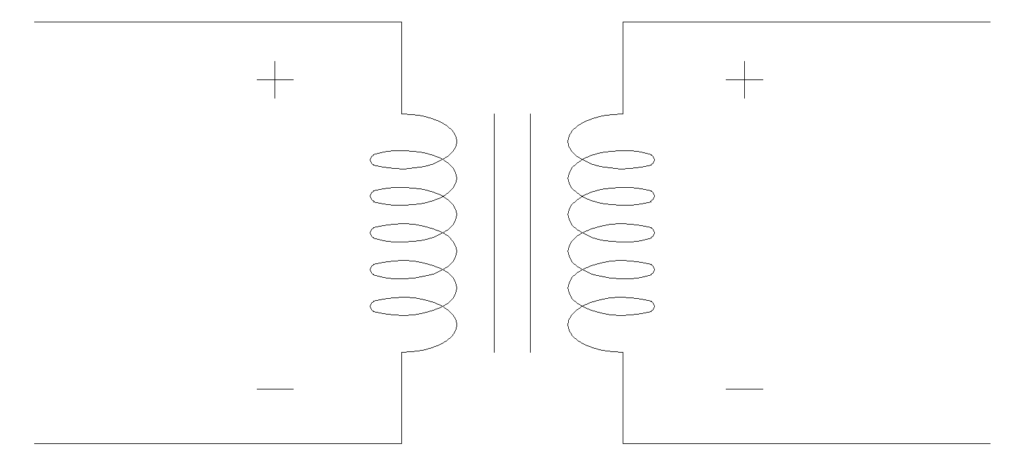
2. Additive Polarity
A transformer has additive polarity when the voltage across the high-voltage (H1) and low-voltage (X1) terminals adds up. In other words, if you connect H1 and X1 with a jumper wire, the voltage measured across H2 and X2 will be the sum of the primary and secondary voltages.
Let’s take an example. Suppose a transformer has a primary voltage of 480V and a secondary voltage of 120V. If the transformer has additive polarity and you short H1 to X1, then the voltage measured between H2 and X2 will be 480 + 120 = 600V. The voltages add because the secondary voltage is in the same direction as the primary voltage between those two terminals.
In transformers with additive polarity, the H1 and X1 terminals are located diagonally opposite to each other. This means if H1 is on the left side of the transformer (when viewed from the high-voltage side), X1 will be on the right side of the low-voltage bushings.
Additive polarity is standard for transformers rated 200 kVA and below, with high-voltage ratings of 8660V and below. This is specified in ANSI C57.12.00.
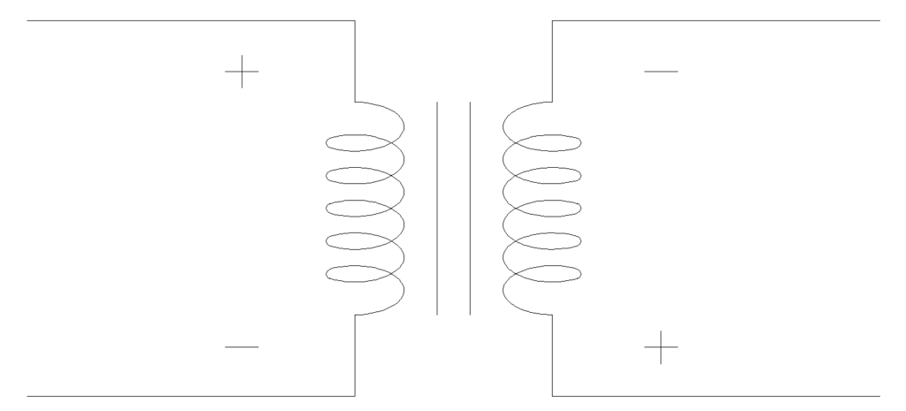
3. Subtractive Polarity
A transformer has subtractive polarity when the voltage across H1 and X1 terminals subtracts. If you connect H1 to X1 with a jumper wire and measure the voltage between H2 and X2, the result will be the difference between the primary voltage and the secondary voltage.
Using the same example as before a transformer with 480V primary and 120V secondary, the voltage measured between H2 and X2 would be 480 – 120 = 360V if the polarity is subtractive.
In subtractive polarity transformers, the H1 and X1 terminals are on the same side. If H1 is on the left side of the transformer (when viewed from the high-voltage side), X1 will also be on the left side.
Subtractive polarity is standard for all transformers rated above 200 kVA or with high-voltage ratings above 8660V. Most power transformers and large distribution transformers use subtractive polarity. This is the more common polarity type in modern power systems and utility-grade equipment.
4. Comparison Table: Additive vs. Subtractive Polarity
Here is a clear side-by-side comparison:
| Feature | Additive Polarity | Subtractive Polarity |
|---|---|---|
| Terminal Position | H1 and X1 are diagonally opposite | H1 and X1 are on the same side |
| Voltage Test Result | V_H + V_X | V_H – V_X |
| Applicable Rating | ≤ 200 kVA and ≤ 8660V HV | > 200 kVA or > 8660V HV |
| Common Usage | Small distribution transformers | Large power transformers |
| ANSI Standard | ANSI C57.12.00 | ANSI C57.12.00 |
| Winding Direction | Secondary wound opposite to primary | Secondary wound same as primary |
5. How to Determine Transformer Polarity?
The polarity of a transformer can be determined using a simple test known as the polarity test. This test requires a voltmeter, a low AC voltage source, and a jumper wire. The steps are as follows:
Step 1: Connect a low AC voltage (such as 120V) to the high-voltage winding (H1 and H2 terminals).
Step 2: Connect a jumper wire between H1 and X1.
Step 3: Measure the voltage across H2 and X2.
Step 4: Compare the measured voltage with the applied voltage.
- If the measured voltage is greater than the applied voltage (sum of voltages), the transformer has additive polarity.
- If the measured voltage is less than the applied voltage (difference of voltages), the transformer has subtractive polarity.
Example:
A transformer has a turns ratio of 4:1. You apply 120V to the primary. The expected secondary voltage is 30V.
- If the measured voltage across H2-X2 is 150V (120 + 30), the polarity is additive.
- If the measured voltage across H2-X2 is 90V (120 – 30), the polarity is subtractive.
This test is commonly performed during transformer acceptance testing and routine maintenance.
6. Additive Polarity vs. Subtractive Polarity — Practical Examples
Example 1: Small Distribution Transformer
A 50 kVA, 4160V/240V single-phase transformer is used in a residential distribution system. According to ANSI standards, this transformer will have additive polarity because its rating is below 200 kVA and the high-voltage rating is below 8660V. The H1 and X1 terminals will be on opposite sides.
Example 2: Large Power Transformer
A 10 MVA, 69kV/13.8kV transformer used in a utility substation will have subtractive polarity. Its rating exceeds both the 200 kVA and 8660V thresholds. The H1 and X1 terminals will be on the same side.
Example 3: Connecting Two Transformers in Parallel
Two 100 kVA, 2400V/240V transformers are to be connected in parallel. Both have additive polarity. The electrician connects H1 of Transformer A to H1 of Transformer B, H2 to H2, X1 to X1, and X2 to X2. The parallel connection works correctly because the polarities match.
If one transformer had additive polarity and the other had subtractive polarity, the secondary terminals would need to be swapped on one transformer (connect X1 where X2 would go, and vice versa) to make the polarities equivalent before paralleling.
7. ANSI Standards for Transformer Polarity
The American National Standards Institute (ANSI) provides clear guidelines for transformer polarity markings and terminal arrangements. The main standard is ANSI C57.12.00 – IEEE Standard for General Requirements for Liquid-Immersed Distribution, Power, and Regulating Transformers.
According to this standard:
- Transformers rated 200 kVA and below with high-voltage ratings of 8660V and below shall have additive polarity.
- Transformers rated above 200 kVA or with high-voltage ratings above 8660V shall have subtractive polarity.
The standard also defines terminal markings. The primary terminals are labeled H1 and H2. The secondary terminals are labeled X1 and X2. For three-winding transformers, the third winding uses Y1 and Y2. The dot convention is sometimes used in schematic diagrams to indicate polarity — dotted terminals have the same instantaneous voltage direction.
Another relevant standard is ANSI C57.12.90, which describes the test procedures for determining polarity in the factory and in the field.
IEEE Std C57.13 covers instrument transformers (current transformers and voltage transformers) and also includes polarity testing guidelines.
8. How to Remember the Difference Easily
Here is a simple memory aid:
- Additive Polarity: H1 and X1 are on opposite sides → voltages add → measured voltage is higher.
- Subtractive Polarity: H1 and X1 are on the same side → voltages subtract → measured voltage is lower.
Another way to remember: “Same side, subtract.” If H1 and X1 are on the same side, it is subtractive.
9. Conclusion
The difference between additive and subtractive polarity comes down to the relative position of the H1 and X1 terminals and the direction of the induced voltage. Additive polarity means the voltages add up across the connected terminals, and H1 and X1 are on opposite sides. Subtractive polarity means the voltages subtract, and H1 and X1 are on the same side. ANSI C57.12.00 defines the standard polarity assignments based on transformer rating and voltage class.
Correct polarity identification is necessary for safe parallel operation, proper instrument transformer connections, and accurate protection relay settings. The polarity test is a straightforward procedure that every electrical engineer and technician should be able to perform. Always verify polarity before connecting transformers in parallel or in a bank, and always follow the applicable ANSI and IEEE standards for terminal markings and test procedures.
10. Frequently Asked Questions (FAQs)
The main difference is the terminal arrangement and the resulting voltage. In additive polarity, H1 and X1 are on opposite sides, and the voltages add. In subtractive polarity, H1 and X1 are on the same side, and the voltages subtract.
Apply a low AC voltage to the primary winding, connect a jumper between H1 and X1, and measure the voltage across H2 and X2. If the measured voltage is higher than the applied voltage, the polarity is additive. If it is lower, the polarity is subtractive.
Yes, but only if you swap the secondary terminal connections on one of the transformers. Without this correction, large circulating currents will flow and can damage both transformers.
Large transformers use subtractive polarity because it is safer for the insulation. In additive polarity, the voltage between adjacent terminals (H1 and X1) can be very high in large transformers, which increases the stress on insulation between bushings.
No. Polarity does not change the voltage ratio or the turns ratio. It only indicates the direction of the induced voltage relative to the primary.
The dot convention uses dots on the schematic to mark terminals that have the same instantaneous voltage polarity. It is a graphical way to represent additive or subtractive polarity in circuit diagrams.
Yes, but for three-phase transformers, polarity is expressed through vector group designations (such as Dyn11) instead of additive or subtractive.
A reversed CT polarity can cause the protective relay to misoperate. It may fail to detect an actual fault or it may trip the circuit during normal operation, depending on the protection scheme.